
1. Design principles and objectives
The system design fully complies with the "Hydrological Testing User Manual" published by China Water Resources and Electric Power PressThe (2013 version) and SL337-2006 "Acoustic Doppler Flow Measurement Specification" were developed and researched, which is a fully automatic remote flow measurement system that integrates measurement, reporting, integration, and calculation. The goal of remote flow measurement for unmanned hydrological cable channels has been achieved, reducing the labor intensity of employees, eliminating potential safety hazards, and improving work efficiency. The measurement accuracy meets the standards and specifications issued by the hydrological industry, and all technical indicators comply with the requirements of relevant hydrological measurement specifications and technical standards. The system has stable and reliable performance, easy operation, and can achieve remote centralized flow control through the network, which has good promotion and use value.
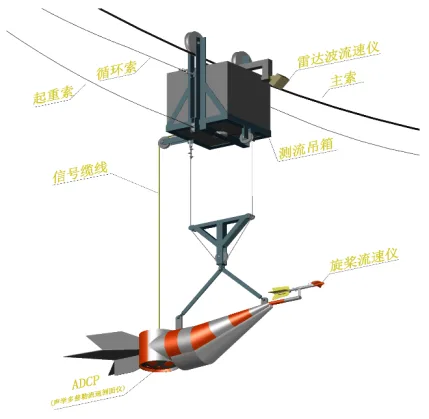
This system uses a cableway as the carrier for equipment operation, which is different from the traditional cableway navigation systemDCPCompared to others, the biggest feature is the use of ADCPThe system couples A for measuring flow on a single point perpendicular lineThere are three flow measurement functions: DCP (Acoustic Doppler Velocimeter), Radar Wave Velocimeter, and Propeller Velocimeter.
This system can simultaneously use three sets of flow measurement devices for flow measurement, or any combination of two sets of flow measurement devices (ADCPcoupled radar wave current meter for flow measurement, ADCPcoupled propeller current meter for flow measurement, and propeller current meter coupled radar wave current meter for flow measurement). In low water levels and stable water flow conditions, ADCP(or propeller current meter) and radar current meter are used by default to measure the flow at the measurement points on the vertical line, making it convenient to compare the two flow measurement systems; When encountering sudden or catastrophic weather conditions such as floods, ADCP (or propeller flowmeter) is unable to measure flow, a separate radar flowmeter can be used for flow measurement.
During flow measurement, the cableway winch, in conjunction with the control system and fully automatic flow measurement software, drives the flow measurement crane box, lead fish, and flow measurement equipment to operate on the main cable by being pulled by the circulating cable. The lead fish and flow measurement equipment move vertically by the lifting cable.
System Composition
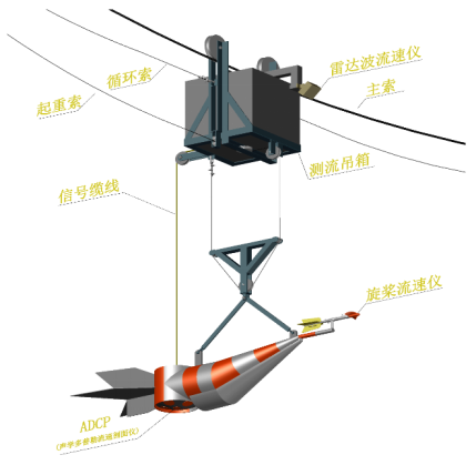
The system is divided into five parts in terms of functional structure: mechanical part, flow measurement part, control part, network construction part, and measurement and control software part. The introduction of each part is as follows:
2.1. The mechanical part is composed of cableways, auxiliary cables, electric winches, traveling frames, and lifting boxes;
2.2. The flow measurement section is composed of lead fish ADCP, Composed of a propeller flowmeter coupled with a radar flowmeter. 2.3. The core control equipment of the control part consists of a computer, an AC frequency converter, and two Siemens PLCs, which work together to complete the signal acquisition, recognition, data calculation, and other tasks of the entire flow measurement system; 2.4. In the network part, the flow measurement system is a small local area network, and data transmission within the network is completed by microwave communication. The connection with external data is achieved through a router, and remote computers can remotely operate and monitor local devices in real time through the router, thereby achieving remote automatic flow measurement function. The data transmission between the computer and the crane is microwave communication, with a transmission distance of over 5KM. The signal transmission has strong anti-interference ability, stable and reliable, providing a safe and reliable guarantee for the transmission of large amounts of data signals such as video surveillance.
2.3. The core control equipment of the control part consists of a computer, an AC frequency converter, and two Siemens PLCs, which work together to complete the signal acquisition, recognition, data calculation, and other tasks of the entire flow measurement system;
2.4. In terms of network, the flow measurement system consists of a small local area network, where data transmission is completed through microwave communication. The connection with external data is achieved through a router, and remote computers can remotely operate and monitor local devices in real-time through the router, thereby achieving remote automatic flow measurement function.
The data transmission between the computer and the crane is microwave communication, with a transmission distance of over 5KM. The signal transmission has strong anti-interference ability, stable and reliable, providing a safe and reliable guarantee for the transmission of large amounts of data signals such as video surveillance.
Data transmission can use satellite and Internet two-way transmission to ensure that in the case of natural disasters, when the Internet cannot transmit data, satellite data transmission is used to achieve the purpose of monitoring the normal operation of the hydrological station.
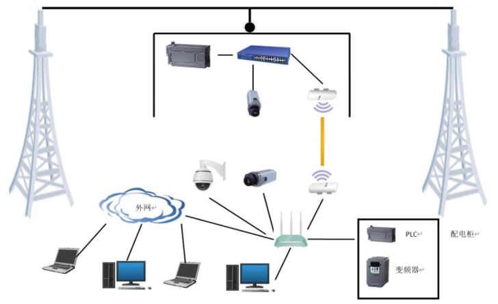
2.5. The measurement and control software has a simple and clear interface, easy operation, and complete functions. The interface is divided into six areas: flow measurement dynamic simulation area, video monitoring area, video operation area, manual operation area, measurement setting area, and status bar.
The measurement and control software has functions such as voice prompts, parameter settings, real-time display of measuring point flow velocity, and fault diagnosis. The operation interface integrates real-time display of flow measurement, video monitoring, rainfall, evaporation, sediment concentration, etc. The measurement and control software can automatically generate measured flow reports with accurate data and standardized recording. The report format should fully comply with the requirements of GB50179 River Flow Measurement Specification and can be directly used for compilation.
ADCP vertical layout:
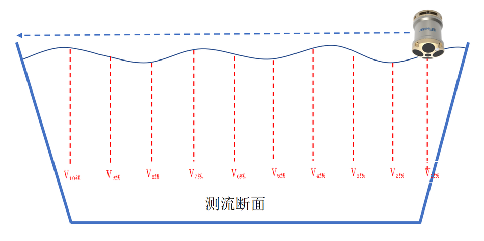
The flow measurement vertical lines are arranged according to the requirements of the "GB 50179-2015 River Flow Measurement Specification". When the flow measurement begins, the lead fish and ADCP are lowered below the water surface, and the vertical lines are measured. The flow measurement time for each vertical line is set between 10s-100s.
As shown in the figure, the red line represents the vertical line arranged for the flow measurement section, and the number of vertical lines can be set according to the width of the river section and the actual situation. The average flow velocity of two adjacent vertical lines is the partial average flow velocity, and the area of water passing between two adjacent vertical lines is the partial area. Multiplying the partial average flow velocity by the partial water passing area equals the partial flow rate, and the sum of the partial flow rates is the cross-sectional flow rate. The average flow velocity Vn line on each vertical line is the flow velocity measured by ADCP on that vertical line.
System features:
1. The system has good scalability and is compatible with propeller current meter, radar current meter, ADCP speed meter, electromagnetic current meter, unmanned aerial vehicle flow measurement, sediment concentration, rainfall and evaporation. Multiple functions can be integrated according to on-site conditions and customer needs.
2. The standard configuration of this system is ADCP coupled radar flowmeter. In low water levels and stable water flow conditions, ADCP and radar flowmeter are used by default to simultaneously measure the flow at the measuring points on the vertical line, making it convenient to compare the two flow measurement systems; When encountering sudden or catastrophic weather conditions such as floods or waterlogging, and ADCP is unable to measure flow, a separate radar current meter can be used for flow measurement.
3. The system makes full use of modern Internet technology and is equipped with an embedded server. It can set up its own LAN to realize online flow measurement, and can also carry out remote flow measurement, remote debugging, remote assistance, automatic update and other functions through the Internet. It can connect tablet computers and support 5G technology.
4. Supports fully automatic unmanned intelligent flow measurement, which can be divided into timed flow measurement and flow measurement based on water level changes.
5. Fully automatic intelligent flow measurement, set the parameters before flow measurement, click on automatic flow measurement start, and the system will automatically complete the entire flow measurement process and generate measurement reports.
6. The automated flow measurement system can integrate three monitoring cameras into the system interface, and the three images can be converted to each other, enabling real-time monitoring of the flow measurement process in all directions, including one 20x ball machine, two gun machines, and real-time monitoring of the entire flow measurement process, as well as the working conditions of the lead fish, water surface, and winch.
7. Based on the characteristics of hydrological cable channels, the system has established multiple models including wire rope sag models, horizontal and vertical motion models, etc. In response to the objective fact that the sag of steel wire ropes is affected by various factors such as environment and temperature, a sag correction model is systematically established and can be adjusted at any time according to the situation.
8. The system adopts AC variable frequency speed regulation and photoelectric coding distance measurement positioning to achieve precise positioning during the flow measurement process.
9. The data transmission from the flow measurement suspension box to the cableway room is dual band, dual loop wireless transmission, with a transmission distance of over 5KM. The signal transmission has strong anti-interference ability, making it safer and more reliable, ensuring real-time and reliable data.
10. Remote data transmission is compatible with the Internet and satellite (optional) dual loop transmission mode to ensure that the Internet is interrupted in case of natural disasters, and satellite data transmission can be used to achieve the purpose of monitoring the normal operation of the hydrological station.
11. For the propeller flowmeter, the flow measurement system has a tremor suppression function to prevent the occurrence of multiple signal recording and ensure the accuracy of the flow measurement signal.
12. Based on the automatic water level gauge, automatically generate a water level process line and plot the measured flow rate on the water level process line.
13. The system report is automatically generated and accurate and reliable. The system will automatically generate data reports after the flow measurement is completed, and the report format fully complies with hydrological specifications and can be directly used for compilation. Before generating the report, if there are any objections to the measurement points, they can be remeasured at any time. Once the report is generated, the data cannot be modified to prevent human tampering with the original data and ensure the authenticity and reliability of the data measurement.
Technical Parameters:
1. Control Part
1.1 Power Supply: 220VAC, 380VAC ± 10%, 50Hz;
1.2 Drive Motor: According to the on-site selection of motor and frequency converter
1.3 Horizontal Operating Speed 1.0m/S;
1.4 Vertical running speed 0.5m/s;
1.5 has limit control settings;
1.6 Starting point distance measurement: Measurement range: -999.9-999.9m; Measurement accuracy: 0.1m (in accordance with hydrological specifications); Signal coefficient of photoelectric encoder sensor: 0.001-9.999; Character and graphic display start distance.
1.7 Depth measurement: Depth range: -99.99-999.99m; Accuracy: 0.01m (in accordance with hydrological specifications); Signal coefficient of photoelectric encoder sensor: 0.001-9.999; Characters and graphics display water depth.
2. Flow velocity measurement
2.1 Adaptability range: 20 revolutions per minute, 5 revolutions per minute, 1 revolution per minute, 1/2 revolution as one signal flow meter (the signal speed value of the flow meter can be set arbitrarily on the upper computer);
2.2 Flow meter formula: V=K * N/T+C, K and C values in the formula can be modified and saved;
2.3 Speed measurement duration: 100S, 60S, 30S... Visible changes in river flood, set and saved according to testing specifications;
2.4 Accuracy: 0.1 seconds; Counting: No error;
2.5 character and graphic display: flow rate, count, timing value.
3. Image monitoring equipment
3.1 Pixel: Infrared network high-definition intelligent ball machine and gun machine with a resolution of over 2 million;
3.2 Video compression standard: H.264/MJPEG;
3.3 Compressed output bitrate: 32Kbps~8Mbps;
3.4 Automatic gain, CCD aperture control, backlight compensation: ON/OFF selectable;
3.5 Communication interface: RJ4510M/100M adaptive Ethernet port;
3.6 Operating temperature and humidity: -30 ° C~+60 ° C, humidity less than 95% (no condensation);
3.7 Required power supply and power consumption: AC220V ± 10%, 50Hz, 7.5W max;
3.8 Size: 195mm x 95mm x 90mm.
3.9 General functions: One click recovery, anti flicker, mirroring, dual stream, heartbeat, password protection, etc
4Radar flowmeter
4.1 Band: 24.000-24.250 GHz
4.2 Speed measurement range: 0.15-15m/s
4.3 Operating distance: 0.5-30m
4.4 Working voltage:+7-28V DC
4.5 Resolution: 0.01 m/s
4.6 Speed measurement accuracy: ± 0.02 m/s
4.7 Start time:<3s
4.8 Measurement time: 3-240 s
4.9 Antenna style: planar microstrip array antenna, 32 ° X14 °
4.10 Transmission power: 26dBm
4.11 Communication interface: RS232 (default)/RS485/SDI-12/4-20mA current loop
4.12 Data format: 9600 (default), 8, n, 1. Baud rate adjustable
4.13 Test angle: built-in automatic angle measurement function, pitch angle of 30-60 degrees automatically calibrated flow rate
4.14 Detection method: non-contact detection
5, ADCP parameters:
5.1 Frequency: 1200kHz
5.2 Maximum current measurement distance: ≥ 35m
5.3 Speed measurement range: ± 10m/s
5.4 Accuracy: ± 0.25% ± 2mm/s
5.5 Resolution: 1mm/s
5.6 layer thickness: 0.06~2m
5.7 Layers: 1-260
5.8 Central depth measurement frequency: 600kHz
5.9 Bottom tracking range: ≥ 45m
5.10 Bottom tracking accuracy: ± 0.25% ± 2mm/s
5.11 Transducer configuration: 5 beams


Leave a Reply