
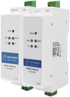
USR-DR30X series manual
Functional characteristics10/100Mbps adaptive Ethernet interface, supporting automatic switching over AUTO-MDIX network cables directly connected
Working mode can be selected from TCP Server, TCP Client, UDP Client, UDP Server, Httpd Client, Modbus TCP
The serial port baud rate can be set from 600bps to 460.8Kbps, and five checks including None, Odd, Even, Mark, and Space are supported.
Customize the heartbeat packet mechanism to ensure authenticity and reliability of connections and eliminate dead connections
Customize the registration packet mechanism to detect the connection status. You can also make a custom packet header. You can choose the MAC address as the registration packet.
In TCP Server mode, the maximum number of connected clients is 8, and the default is 4
In TCP Server mode, when the number of connections reaches the maximum, whether new connections will kick out old connections can be set
Supports web pages, AT commands, and serial protocol for customers to integrate into their own software
Support TCP Client short connection function, customize short connection disconnection time
Supports timeout restart (no data restart) function, and the restart time is customized
Whether the data cache is cleared before establishing a TCP connection can be set
DHCP function, which can automatically obtain IP;DNS function, domain name resolution;DNS server address can be customized
Upgrading firmware functions through the network makes it more convenient to upgrade firmware
Support virtual serial ports and support USR-VCOM software independently developed by others
It can operate across gateways, switches, and routers; it can work on a local area network or access an external network
Support watchdog function
Supports both software and hardware restoration of factory settings
1. Product Overview1.1. product introduction
USR-DR30X is a rail-type single serial port server launched by Internet of Things Technology Co., Ltd. It is a device that realizes direct data between the RJ45 network port and the RS232/RS485 interface.
Transparent transmission devices are equipped with ARM processors, with low power consumption, high speed and high stability.
The optimized TCP/IP protocol stack is integrated internally, allowing users to easily complete the network functions of embedded devices, saving manpower, material resources and development time.
This series of products has gone through rigorous testing and can be used in complex network environments such as banks, highways, large corporate networks, busy networks with cameras, and optical fiber to Ethernet.
Both have been successfully applied.
USR-DR30X series serial server models include USR-DR301 (serial RS232) and USR-DR302 (serial RS485). In order to meet the needs of more customers, we provide
Available in 2 specifications on demand.
1.2. Basic Parameters
Table 1 Basic Parameters Table
| Classification Parameter Item Values |
| Hardware parameters |
Working voltage DC 5.0~ 36.0V
| Working current |
130mA@5V |
| Network port specifications |
RJ45, 10/100Mbps, cross-direct adaptive |
| Serial port baud rate |
600-460.8K (bps) |
| Data bits |
7, 8 |
| Check bits |
None, Odd, Even, Mark, Space |
|
| Serial ports |
USR-DR301: RS232*1
USR-DR302: RS485*1 |
| Software Parameters |
Network Protocol |
IP, TCP/UDP, ARP, ICMP, IPV4, HTTP |
| IP acquisition method |
Static IP, DHCP |
| Domain name resolution |
Support |
| User configuration |
Software configuration, web configuration, AT command configuration |
| Simple pass-through method |
TCP Server/TCP Client/UDP Server/UDP Client |
| Class RFC2217 |
Support |
| Httpd Client |
Support |
| TCP Server connections |
Support up to 8 TCP connections (customizable) |
| Network cache |
Send: 6Kbytes; receive: 4Kbytes |
| Serial cache |
Receive: 2Kbyte |
| Average transmission delay |
<10ms |
| Supporting software |
Virtual serial port, transparent cloud, parameter setting software |
| Packaging mechanism |
4 byte packaging time, 1024 byte packaging length |
| Other |
Reliability level |
1.5KV electromagnetic isolation |
| size |
109.66*28.0*64.71 (mm)(L*W*H) |
| Working temperature |
-40  ̄ 85 ℃ |
|
Storage temperature |
-40  ̄ 105 ℃ |
| Operating humidity |
5%~95% RH(no condensation) |
| Storage humidity |
5%~95% RH(no condensation) |
2. Hardware parameters2.1. Product size
The overall size of the USR-DR30X is 109.66*28*64.71mm
The specific size is as shown in Figure 1: Unit mm
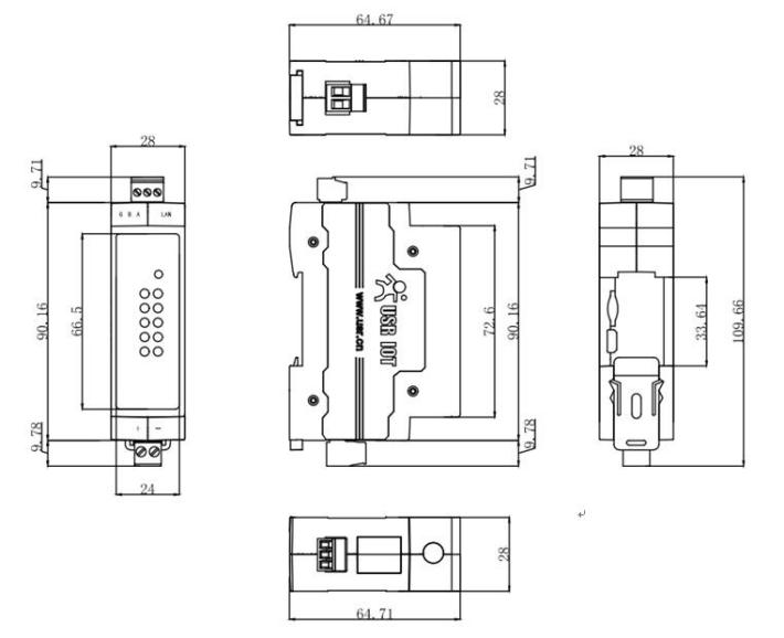 Figure 1. USR-DR30X size diagram
2.2. restore the factory settings
Hardware restoration of factory settings: Press the Reload button between 5 and 15 seconds to restore factory settings. If it is less than 5 seconds or more than 15 seconds, the factory settings will not be restored. will not perform
Restore factory settings. When the module is configuring confusing parameters or forgets to set a password, you can use the hardware restore factory settings function.
Software restores factory settings: Restore factory settings through the setting function of the setting software or send a restore factory settings command through the network protocol.
AT command to restore factory settings: Enter AT command mode and use command AT+RELD to restore factory settings.
2.3. Introduction to indicator lights
The USR-DR30X series has a front indicator for easy observation of working conditions.
Table 2 Indicator and Reload Instructions
| Network name |
Description |
| PWR |
The power indicator lights red and lights up after power supply, and goes out after power failure |
| WORK |
Work indicator Single-chip work indicator, the lamp flashes after power up |
| TX |
Serial port transmission indicator flashes when serial port transmits data |
| RX |
Serial port reception indicator flashes when serial port receives data |
2.4. Interface introduction
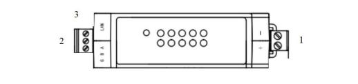 Figure 2. USR-DR30X serial server interface definition
Table 3 Interface description
Figure 2. USR-DR30X serial server interface definition
Table 3 Interface description
| Pin |
Name |
Description |
| 1 |
Power supply interface |
Serial server power input interface: 5V-36V, wired according to + and-logos. |
| 2 |
Serial |
USR-DR301 is an RS232 interface
USR-DR302 is an RS485 interface
According to the logo, there are A/T, B/R, and G |
| 3 |
Ethernet ports from right to left |
Ethernet cable interface |
3. Product Features3.1. Function Introduction
This chapter systematically introduces the functions of the DR30X series. During use, functions and parameters can be set through web pages, host computer software, and AT instructions. This chapter mainly
Function descriptions are provided on the web page and host computer software. See Chapter 4 for details of AT command settings. The default parameters are as follows:
Login method: username/password are admin;
Serial port parameters: baud rate 115200, data bits 8, check bit NONE, stop bit 1;
Network port parameters: IP address 192.168.0.7, subnet mask 255.255.255.0, gateway 192.168.0.1;
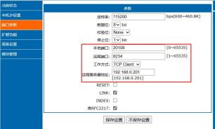
Entry test: TCP Client in working mode, remote server address 192.168.0.201, remote port 8234.
The following figure is the overall functional block diagram to facilitate overall product awareness.
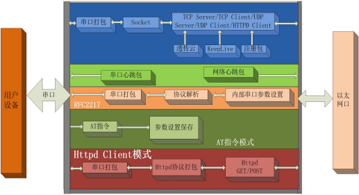
图
3. DR30X Functional Block Diagram3.2. network settings
This section mainly introduces the basic functions of the network. All parameters involved are mainly used for normal communication connection and data interaction between network equipment and the connected network.
3.2.1. Status overview
Users can set parameters through the DR30X's built-in web server, or view the relevant status of the device through the web page. Among them, the port number of the web server can be set, silent
Think 80. Use as follows:
1) Open a browser and enter the IP address of DR30X in the address bar, such as 192.168.0.7 (the IP address and the computer are on the same network segment).
2) Enter the username and password in the pop-up login interface. The default username and password are admin. After clicking "OK", you can enter the main interface of the built-in web page.
3) The main interface is the status interface. It can display the IP of the currently connected device, the number of bytes sent and received data per connection, as well as the total number of data sent and received by the server.
Byte count statistics.
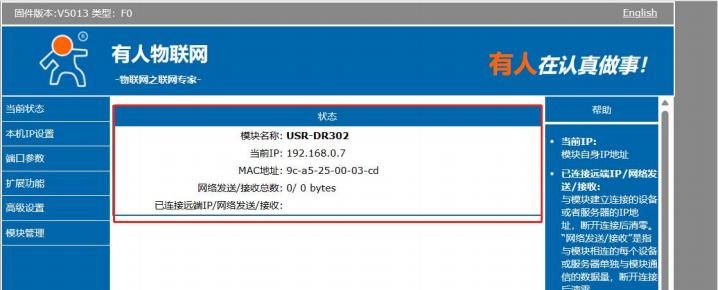 Figure 4. Screenshot of current status display
3.2.2. IP address/DHCP/DNS
Click "Network Parameters" to set basic network parameters such as IP address, subnet mask, gateway, and DNS server.
There are two ways to set the IP address, one is static IP and the other is DHCP.
The static IP of the module needs to be set manually by the user, and the IP, subnet mask and gateway need to be written at the same time. The static IP is suitable for scenarios where statistics on IP and devices need to be made and corresponding one by one. Using static IP requires setting each module and ensuring that the IP address is not duplicate within the local area network and other network devices.
The main role of DHCP is to dynamically obtain IP address, Gateway address, DNS server address and other information from the gateway host, thus eliminating the cumbersome steps of setting IP address. applicable
There are no requirements for IP, and there is no requirement for one-to-one correspondence between IP and modules.
Table 4 Comparison of advantages and disadvantages of DHCP static IP
| IP method |
Advantages |
Disadvantages |
| Static IP |
enables IP and DR30X to correspond one to one, regardless of whether
Modules can be quickly searched for in any environment |
Need to be adjusted according to different access network parameters and need to be set correctly
has certain technical requirements for the person who sets the IP address. |
| DHCP |
By directly connecting to a network with IP allocation capabilities, you can obtain the correct parameters for communication. You
Make it plug and play. |
You cannot use it directly with your computer. You must attach it to a computer that has IP allocation capabilities.
Under the power equipment. |
The DNS server address can be set, which can realize domain name resolution when the local domain name server is imperfect. Users can also set the address of a specific DNS server according to their needs.
When the DR30X needs domain name resolution, it will submit a resolution request to the configured DNS server. It is more flexible and reliable to use.
In static IP mode, the DNS server address defaults to 8.8.8.8. In DHCP mode, the DNS server address is obtained automatically. Supported domain name server address can be set.
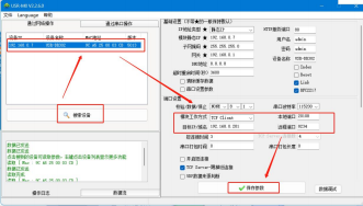
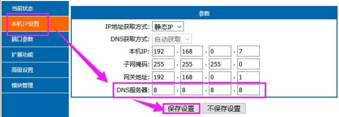 Figure 5. Software setting parameters
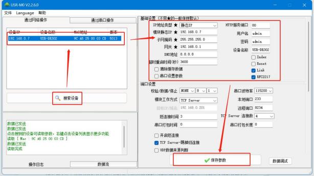 Figure 6. Software Setting Parameters
3.3. Serial port settings
3.3.1. Basic parameters of serial port
The basic parameters of the serial port are the guarantee for normal communication of the serial port, mainly including: baud rate, data bit, stop bit, and check bit.
Baud rate: serial communication rate, supports custom values, can be set in the range: 600~460.8Kbps;
Data bit: The length of the data bit, ranging from 7 to 8;
Stop bit: The settable range is: 1~2;
Check bit: Check bit for data communication, supporting five verification methods: None, Odd, Even, Mark, and Space.
By setting the serial port parameters and keeping the serial port parameters consistent with the serial port parameters of the serial port connected device, the normal communication can be ensured.
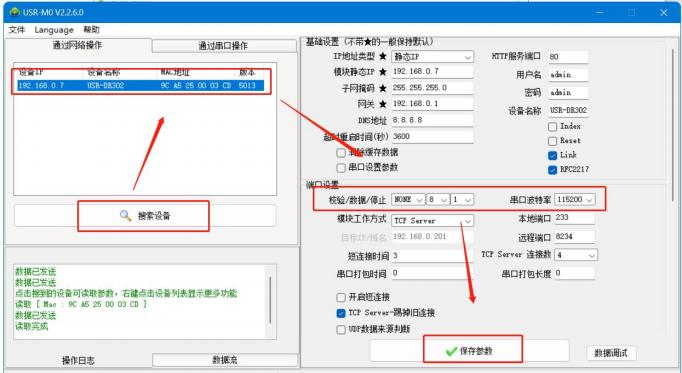 Figure 7. Serial port basic parameter settings
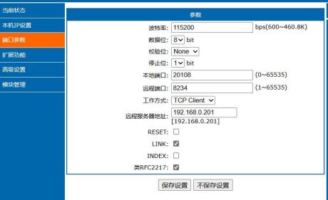 Figure 8. port parameters
3.3.2. Serial port framing mechanism
Since the data on the network is transmitted in data frames, the data from the serial port needs to be sent to the network in frames, which can be more efficient and faster.
Transfer data. During the transparent data transmission process, the DR30X packages serial data according to a fixed packaging length and packaging time.
The serial port framing mechanism depends on the packaging time and the packaging length. When either one is satisfied, it is packaged and sent.
Serial port packaging time: The default is 4 bytes of transmission time.
Serial port packaging length: The default is 1024 bytes packaging length.
3.4. working mode
DR30X's Socket working modes are divided into five types: TCP Client, TCP Server, UDP Client, UDP Server, and Httpd Client. They can be accessed through the web page and configuration software.
Settings, the setting interface is as follows:
Figure 9. Example of working mode settings3.4.1. TCP Client Mode
TCP Client provides client connections to TCP network services. Actively initiate a connection request to the server and establish a connection to realize the interaction between serial data and server data. According to the relevant regulations of the TCP protocol, TCP Clients are distinguished between connection and disconnection, thereby ensuring reliable exchange of data. Generally used for data interaction between a device and a server, it is the most common
The networked communication method used.
 Figure 10. TCP Client Mode Description
1) This mode has the function of proactively identifying connection abnormalities. After the connection is established, KeepAlive keep-alive probe packets will be sent at an interval of about 15 seconds. If there is an exception in the connection,
Interruptions and other conditions will be immediately detected and prompt the DR30X to disconnect the original connection and reconnect.
2)When the DR30X attempts to connect to the server in TCP Client mode and the local port is 0, it initiates the connection with a random port every time.
3)Under the same local area network, if DR30X is set to static IP, please keep the IP of DR30X and the gateway on the same network segment, and set the gateway IP correctly, otherwise it will not work normally
Communications.
4)This mode supports autonomous synchronous baud rate function, transparent cloud transmission function, and also supports short connection function.
5)DR30X acts as a TCP Client. When connecting to a TCP Server, it needs to pay attention to parameters such as target IP/domain name and target port number.
6)As a TCP Client, the DR30X will proactively connect to the target port of the target IP and will not accept other connection requests.
3.4.1.1. short connection
TCP short connections are mainly used to save server resources and are generally used in multi-point-to-point scenarios. Using short connections ensures that all existing connections are useful connections and no additional control means are needed to filter.
The TCP short connection function is applied in TCP Client mode. After the short connection function is turned on, information is sent. If no data is received from the serial port or network port within the set time, it will automatically
Disconnect the connection. This function is turned off by default, and the disconnection time can be set after the function is turned on. The setting range is 2 to 255 seconds, and the default is 3 seconds. The setting diagram is as follows:
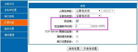 Figure 11. Short connection setting diagram
3.4.1.2
Figure 11. Short connection setting diagram
3.4.1.2. heartbeat packet function
In network transparent mode, users can choose to let the DR30X send heartbeat packets. Heartbeat packets can be sent to the network server or to the serial device, and cannot be sent at the same time.
Okay.
The main purpose of sending to the network is to maintain the connection, ensure reliable connection, and eliminate dead links. It only takes effect in TCP Client and UDP Client modes. When there is data on the Internet port
When sending, the network heartbeat packet stops.
In applications where the server sends fixed query instructions to the device, in order to reduce communication traffic, the user can choose to send a heartbeat packet (query instructions) to the serial device instead of
Send query instructions from the server. When data is sent from the serial port, the serial port heartbeat packet does not stop.
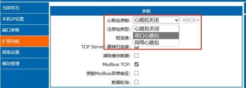 Figure 12. Heartbeat Packet Settings
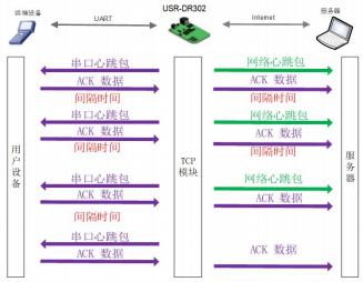 Figure 13. Diagram of heartbeat packet function
3.4.1.3
Figure 13. Diagram of heartbeat packet function
3.4.1.3. Register Package Function
In transparent network mode, users can choose to have the module send registration packages to the server. Registration packages are used to allow the server to identify the device from which the data originated, or as a way to obtain server functionality.
A password that can be authorized.
There are three types of registration packages: transparent cloud, MAC registration package, and custom registration package.
The registration package can be sent when the module establishes a connection with the server, or the registration package data can be spliced into the front end of each packet as a single packet. Registration package data can
MAC address or custom registration data, where the maximum length of the custom registration package setting content is 40 bytes.
Establishing a connection and sending registration packages is mainly used to connect to servers that need to be registered. The application schematic diagram is as follows:
 Figure 14. Establish a connection and send registration packet
Data carrying registration packet: The transmitted data is connected to the registration packet at the front end of the data, which is mainly used for protocol transmission. The application diagram is as follows:
 Figure 15. Data Carrying Registration Package
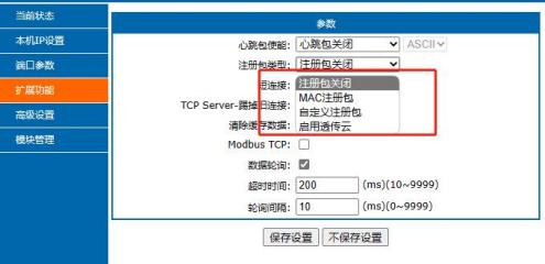 Figure 16. Registration package settings
3.4.1.4
Figure 16. Registration package settings
3.4.1.4. Clear cached data
When a TCP connection is not established, the data received by the serial port will be placed in the buffer area. The DR30X serial port receiving buffer is 2Kbytes. When the TCP connection is established, the serial port cached data can be set whether to be cleaned according to customer needs. This function defaults to no cleanup. When the short connection function is enabled in Httpd Client mode or TCP Client mode, the function of clearing cached data is lost.
Effective. The setting diagram is as follows:
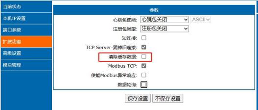 Figure 17. Clear cached data setting diagram
3.4.2. TCP Server mode
TCP Server is TCP server. In TCP Server mode, the DR30X listens on the local port, accepts and establishes a connection for data communication when a connection request is sent. When the DR30X serial port receives data, it will simultaneously send the data to all client devices that establish connections with the DR30X. The same TCP Server mode also has the KeepAlive function for real-time monitoring of connections.
complete.
Generally used for communication with TCP clients within a local area network. It is suitable for scenarios where there is no server in the local area network and multiple computers or mobile phones request data from the server. Same as TCP Client
There is the same distinction between connection and disconnection to ensure reliable exchange of data. This mode supports the autonomous synchronized baud rate (RFC2217) function.
When the DR30X is used as a TCP Server, it can accept up to 8 Client connections (the number of connections can be customized). The local port number is a fixed value and cannot be set to 0.
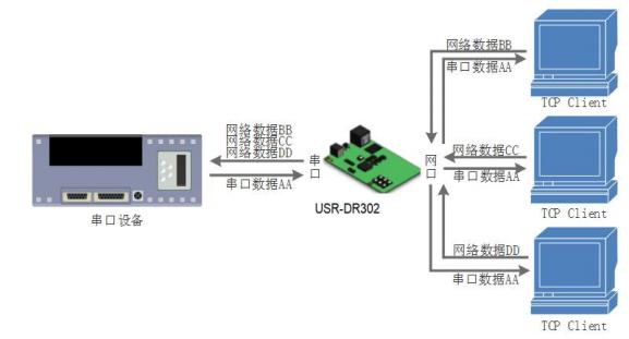 Figure 18. TCP Server Mode Description
3.4.2.1
Figure 18. TCP Server Mode Description
3.4.2.1Custom Client Connections
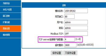
When the USR-DR30X is used as a TCP Server, the number of clients that can be connected to is up to 8, and the default value is 4. The maximum value can be set according to customer needs to make it convenient for customers to use. When the number of connected clients exceeds 4, if sending and receiving are simultaneously, the total data traffic needs to be controlled within 2.5KB/s (that is, each connection sends no more than 200 bytes of information per second).
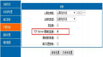
When the number of Client connections is greater than the maximum value set by the user, the new connection will replace the old connection by default, or it can be set so that the new connection cannot kick the old connection. Set up the schematic through the webpage
As follows:
Figure 19. Setting diagram3.4.3. UDP Client mode
This working mode belongs to the UDP protocol. UDP Client is a connectionless transfer protocol that provides simple and unreliable transaction-oriented information transfer services without connection establishment and disconnection
Open, you only need to set the IP and port to send data to each other. Generally used for the number of packets that have no requirement on packet loss rate, small packets and fast sending frequency, and the number of data to be transmitted to the specified IP
According to the transmission scenario.
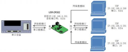 Figure 20. UDP Client Mode Description
1) In UDP Client mode, the DR30X serial port from the network will only communicate with the target port of the target IP. If the data does not come from this channel, the data will not be transmitted to the DR30X
Receive.
2)In this mode, if the target address is set to 255.255.255, the effect of UDP broadcast on the entire network segment can be achieved; broadcast data can also be received; firmware supports network
Broadcast within a segment, such as xxx.xxx.xxx.255. Multicast is not supported.
3.4.4. UDP Server mode
UDP Server means that the source IP address is not verified on the basis of ordinary UDP. After receiving a UDP packet, the destination IP is changed to the data source IP and port number. When sending data, the IP and port number sent to the most recent communication. This mode is usually used for multiple network devices that need to communicate with the module and do not want to use TCP due to the high speed and frequency
According to the transmission scenario.
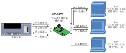 Figure 21. UDP Server mode
3.4.5. Httpd Client mode
In this mode, the user's terminal device can send request data to the designated HTTP server through the DR30X serial server, and then the DR30X receives request data from the HTTP service.
The data is parsed and the results are sent to the serial device.
Users do not need to pay attention to the data conversion process between serial data and network data packets. They only need to set up simple parameters to realize the request for data from serial devices to HTTP servers.
Please. The specific working diagram and setting example diagram of Httpd Client mode are as follows:
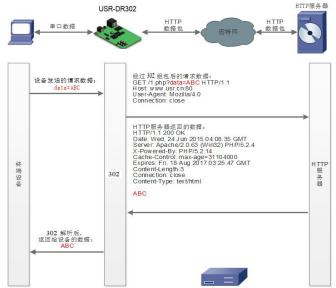 Figure 22. HTTPD Client Mode Description
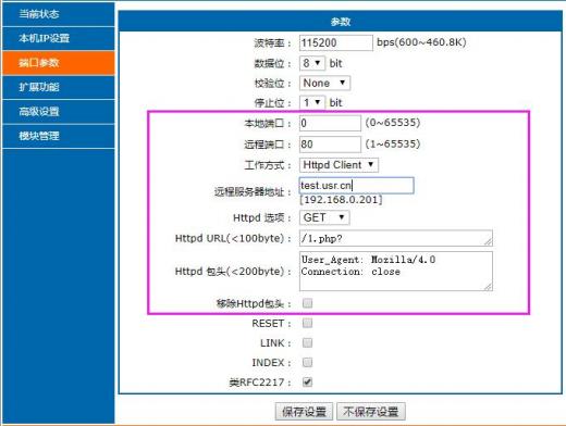 Figure 23. Httpd Client setting diagram
3.4.6. Virtual Serial Tool VCOM
 Figure 24. VCOM Application Diagram
By using the supporting software VCOM(virtual serial port), it receives data from the specified virtual serial port, and then sends the data in the form of network data, thereby solving the problem that the PC-side software is
The problem of being unable to communicate with networked devices due to serial port mode is convenient for users to use.
USR-VCOM software download address
https://www.usr.cn/Download/31.html
3.5. Modbus Gateway Function
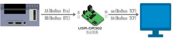
Modbus Gateway includes: conversion between Modbus RTU and Modbus TCP protocols.
图
25. Modbus Protocol Conversion Functional Block DiagramModbus RTU and Modbus TCP: Conversion from Modbus serial protocol to Modbus network protocol can be realized by setting
Activate the Modbus TCP to Modbus RTU function via the webpage:
Start process:
First make the module work in TCPserver or TCPclient mode
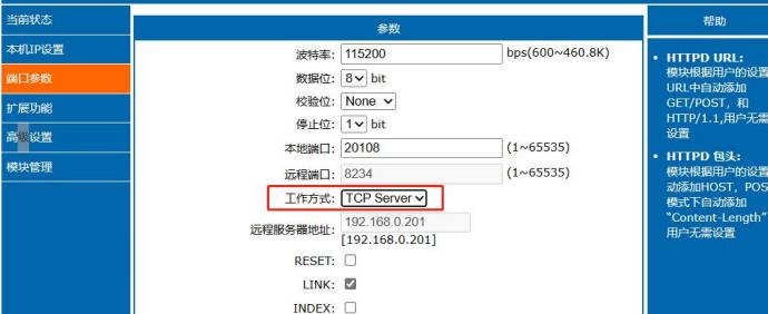 Figure 26. Port Parameter Setting Diagram
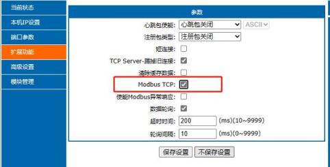 Figure 27. Open Settings Chart
Click the Modbus TCP check box with the mouse to check to turn on the function, and uncheck the close function. This function is turned off by default.
3.6. Features
3.6.1. Reset function
The Reset function is mainly used to initialize the module by restarting when the DR30X program runs away or crashes and cannot establish the link normally and cannot work normally, so that the DR30X can resume normal work under certain circumstances. When DR30X acts as a TCP Client, DR30X actively connects to the TCP Server. When the Reset function is activated, the DR30X
If you try to connect to the TCP Server 30 times and still fail to establish a connection, the DR30X will automatically restart. The functional switches are as follows:
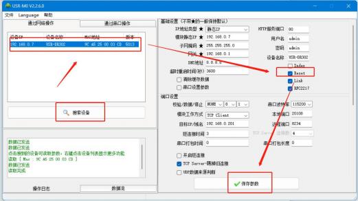 Figure 28. Reset function setting
3.6.2. Index function
The Index function mainly solves the problem that in TCP Sever mode, when a user has multiple clients connected to the DR30X and sent and received data at the same time, the data source cannot be distinguished or sent to a specific one.
The situation of the client.
When DR30X is used as a TCP Server, a maximum of 8 connections can be established at the same time, and the maximum value can be set arbitrarily within the range of 1-8. Here, the default value of 3 connections is taken as an example. When the Server sends data to three clients at the same time, or when the Server receives Client data, after the Index function is turned on, different clients will be labeled. Customers can label them based on the information.
To distinguish the data source that receives the data, and can also send different information to specific clients based on the protocol.
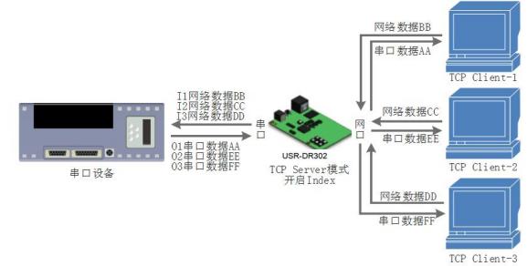 Figure 29. Index function example diagram
setting diagram is as follows:
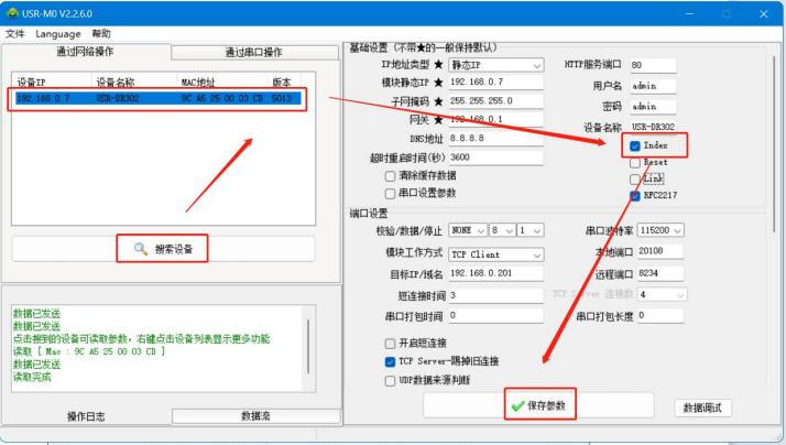 Figure 30. Index setting diagram
3.6.3. Class RFC2217
Similar to RFC2217, it is a simplified version of the RFC2217 protocol. With the virtual serial port, it can dynamically change the serial port parameters of the DR30X, and it can realize communication with devices that change serial port parameters (such as baud rate, data bits, check bits, etc.). After turning on this function, use the USR-VCOM virtual serial port software to also turn on RFC2217-like functions, so you can implement application software on your computer.
The serial baud rate of the device is automatically matched with the serial baud rate of the DR30X, without paying attention to the baud rate setting of the serial port. The setting diagram is as follows:
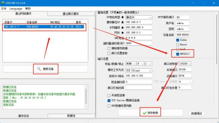 Figure 31. Class RFC2217 Function Settings
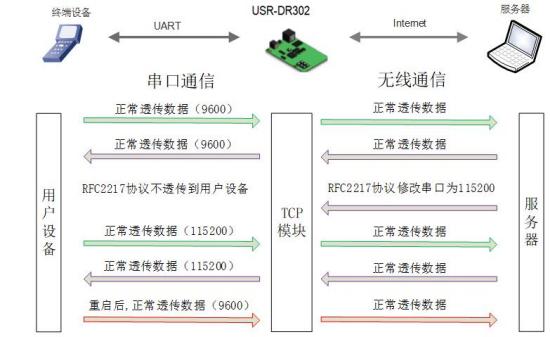 Figure 32. Class RFC2217 Functional Diagram
3.6.4. Customize web features
The custom web feature allows you to upgrade your own style of web code to your device. Convenient for users. Use of this feature requires the help of a web upgrade package, which includes two web pages
Code (DR30X default web page code and DR30X neutral web page code), web page upgrade tool.
Implementation steps:
Download the software you need on the custom web page. Link:
http://www.usr.cn/Download/880.html
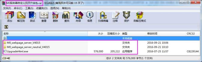 Figure 33. Custom Web Page Upgrade Package
You need to pay attention when upgrading a custom web page. The Destination IP is set to the IP address of DR30X, and the final web page file name must be "fs". Select "M0" for the product. Confirm
Then click "Upgrade" to upgrade.
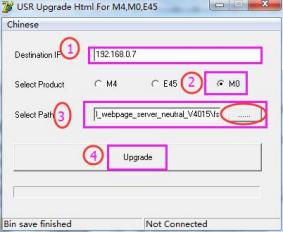
图
34. Instructions for using customized web page upgrade software3.6.5. Timeout restart
The timeout restart (no data restart) function is mainly used to ensure the long-term stable operation of the DR30X. When the network port fails to receive data for a long time, or the network does not receive data for a long time, the DR30X will restart after the set time, thereby avoiding abnormal situations that affect communication. The timeout restart time can be set through the web page, and the normal working time of this function is set to
60~65535s, the default value is 3600s. When the setting time is less than 60 seconds, the function is turned off by default. The setting diagram is as follows:
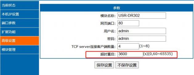 Figure 35. Timeout restart function
3.6.6. firmware upgrade
If the module needs to be upgraded to a higher version of firmware, the user can consult the business person to upgrade the firmware, click on the device after getting the upgraded firmware, and then upgrade the firmware. When upgrading firmware, it is best for the computer to be directly connected to the module, and ensure that the device IP and the computer IP are on the same network segment. The computer is prohibited from upgrading module firmware through wifi.
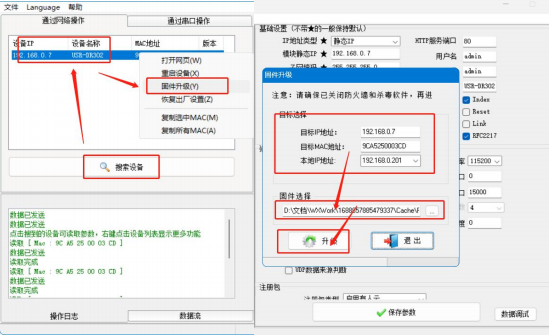 Figure 36. Firmware upgrade
3.6.7. data polling
The data polling function is mainly used to solve the problem of misaligned replies from serial devices after multiple network devices send data at the same time. It can identify and respond data sent by different network devices.
Recovery to prevent data misplacement.
Note: The polling function is turned on, and the DR30X can only be used as a slave device and has no host mode.
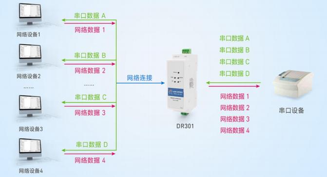 Figure 37. Polling function diagram
3.6.7.1
Figure 37. Polling function diagram
3.6.7.1. Function activation and parameter configuration
Set and enable the data polling function in the web extension function interface, and set two polling parameters:
(1) Timeout time: The time interval from the time when DR30X finishes sending a frame of data to the lower serial device until the serial device replies data to DR30X; the default is 200ms; setting range: 10~9999 (ms).
(2) Polling interval: The time interval from the DR30X successfully throws the received reply data from the lower serial device to the network end to the DR30X sending the cached polling data to the serial device again; the default value is 10ms, and the setting range is 0~9999 (ms).
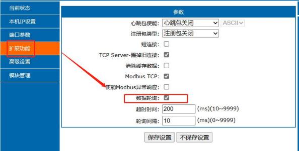 Figure 38. Polling function parameter setting diagram
3.6.7.2
Figure 38. Polling function parameter setting diagram
3.6.7.2. Example of application scenarios
(1) MODBUS+ polling:
① Turn on MODBUS TCP function
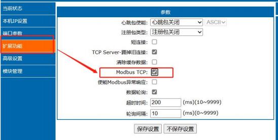 Figure 39. MODBUS TCP enable setting diagram
② Enable MODBUS exception response (Note: It is only effective under polling function)
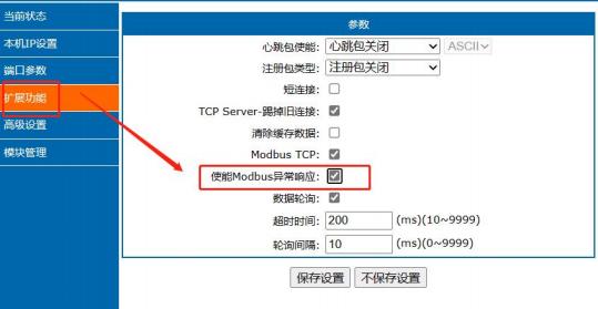 Figure 40. MODBUS exception response enable setting diagram
This function can be turned on or off independently according to needs. After the function is turned on, the DR30X replies to the timeout on the lower serial port or receives an erroneous MODBUS RTU protocol frame,
The host replies with an exception frame carrying the error code. The function is turned off, and the DR30X will not respond to abnormal frames when the lower serial port reply times out or when an erroneous MODBUS RTU protocol frame is received.
③ Turn on the polling function and set polling parameters:
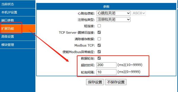 Figure 41. MODBUS exception response enable setting diagram
(3) Autonomous protocol (transparent transmission)+ polling:
Turn on polling function and set polling parameters:
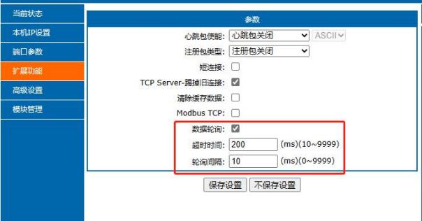 Figure 42. MODBUS Exception Response Enable Setting Illustration
This mode is suitable for scenarios that use autonomous protocols for data collection, and can satisfy the multi-scenario collection mode to the greatest extent. The timeout and polling interval in this scenario have been set
It all depends on the application scenario and requires the ability to set parameters independently.
4. AT Command Configuration4.1. Overview of AT instructions
The AT command refers to the instruction set that the user transfers commands to the module through UART in command mode. The usage format of the AT command will be explained in detail later. After successful power-on,
Modules can be set through UART.
The default UART port parameters of the module are: baud rate 115200, no check, 8 data bits, and 1 stop bit.
<Description>AT command debugging tool AT Setup, which is used to demonstrate the following introduction. The DR30X series uses AT Setup software to send "+++a" from transparent mode, data window
You will receive an "a+ok" indicating that the device has entered command mode.
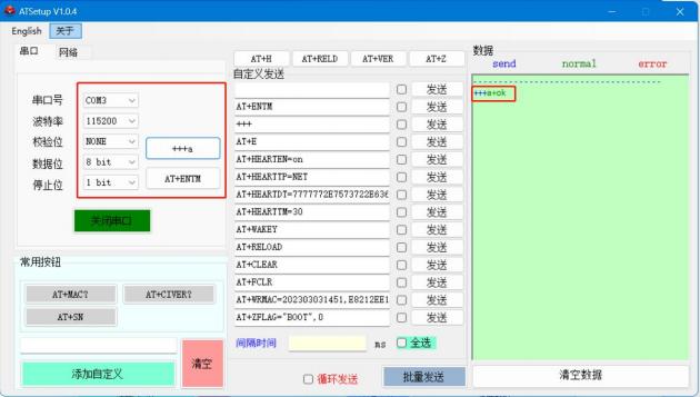 <Description>
When entering "+++" and the confirmation code "a", there is no echo, as shown in the figure above.
Entering "+++" and "a" needs to be completed within a certain period of time to reduce the probability of accidentally entering the command mode during normal work. The specific requirements are as follows:
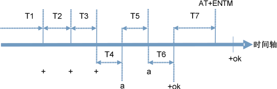
Time requirements: T1 > serial port packaging interval;T2 < 300ms;T3 < 300s;T5 < 3s
Timing for switching from transparent mode to temporary command mode:
The serial device continuously sends "+++" to the module. After the module receives "+++", it will send an 'a' to the device. Any item cannot be sent during the packaging time before sending "+++"
What data.
When the device receives an 'a', it must send an 'a' to the module within 3 seconds.
After receiving the 'a', the module sends "+OK" to the device and enters the "AT command mode".
After the device receives "+OK", it knows that the module has entered "AT command mode" and can send an AT command to it.
Timing for switching from AT command mode to network transparent transmission:
The serial device sends the command "AT+ENTM" to the module.
After receiving the command, the module echoes "+OK" and returns to the previous working mode.
The error code is as follows:
4.2. AT command set
Table 5 Error Code List
| Error Code |
Description |
| 1 |
Invalid command format, does not match the AT instruction format |
| 2 |
Invalid command, the AT instruction did not find |
| 3 |
Invalid operator, does not match the query or setting format |
| 4 |
Invalid parameter, parameter range or quantity error |
| 5 |
Operation not allowed |
Table 6 AT+ Command List
| Number |
Command |
Description |
| 1 |
E |
Turn on/off echo function |
| 2 |
Z |
Restart module |
| 3 |
H |
Help |
| 4 |
VER |
Query version number |
| 5 |
ENTM |
Exit AT command mode |
| 6 |
RELD |
Restore factory settings |
| 7 |
MAC |
Query module MAC |
| 8 |
WEBU |
Set/query username and password |
| 9 |
WANN |
Set/query WAN port parameters |
| 10 |
DNS |
Set/query DNS server address |
| 11 |
WEBPORT |
Set/query web port number |
| 12 |
UART |
Set/query serial port parameters |
| 13 |
SOCK |
Set/query SOCK parameters |
| 14 |
TCPSE |
Set/query whether to kick old connections |
| 15 |
SOCKLK |
Query TCP connection status |
| 16 |
SOCKPORT |
Set/query local port number |
| 17 |
RFCEN |
Set/query class RFC2217 enable |
| 18 |
PDTIME |
Query production time |
| Heartbeat packet function command |
| 19 |
HEARTEN |
Set/query heartbeat packet enable |
| 20 |
HEARTTP |
Set/query heartbeat packet sending method |
| 21 |
HEARTDT |
Set/query custom heartbeat packet data |
| 22 |
HEARTTM |
Set/query heartbeat packet time |
| Register packet function instructions |
| 23 |
REGEN |
Set/query registration packet mechanism |
| 24 |
REGTCP |
Set/query registration packet execution mechanism |
| 25 |
REGCLOUD |
Set/query transparent cloud user name and password |
| 26 |
REGUSR |
Setting/Query the content of the user-defined registration package |
| Httpd Client Function Command |
| 27 |
HTPTP |
Set/Query In Httpd Client mode, HTTP request method |
| 28 |
HTPURL |
Set/query URL in Httpd Client mode |
| 29 |
HTPHEAD |
Set/query header in Httpd Client mode |
| 30 |
HTPCHD |
Set/query HTTP header function |
| Extended function command |
| 31 |
SCSLINK |
Set/Query Socket connection status indication function |
| 32 |
CLIENTRST |
Set/query TCP Client mode connection failure Reset function |
| 33 |
INDEXEN |
Set/query index function |
| 34 |
SOCKSL |
Set/query short connection function |
| 35 |
SHORTO |
Set/query short connection time |
| 36 |
UARTCLBUF |
Set/query whether to clear serial cache before module connection |
| 37 |
RSTIM |
Set/query timeout restart time |
| 38 |
MAXSK |
Set/query TCP Server connection Client maximum value |
| 39 |
MID |
Set/query module name |
| 40 |
MODTCP |
Set/query Modbus TCP functions |




Leave a Reply