
Preface
When connected to "TCP/IP" or "UDP/IP", it can work as a client or server respectively
Among them, the slave address 0 is exclusively used for "broadcast mode", that is, the master station sends requests to all slave stations. The slave station did not respond to the broadcast request from the master station, and the broadcast request is generally used to write commands.
- The free protocol is used to support Modbus common function codes, Modbus user-defined function codes, and "free port" communication outside of Modbus that are not provided in this application.
- Upgrade the target framework to .NET 7.0;
- Support multiple languages: Chinese (Simplified Chinese) , English, French and German;
- Fixed other defects.
Recent updates
- To meet the needs of accessing register data of different types and formats at once, Improved data setting function. Can define the types of each data item in the data list separately, Format and Encoding;
- Comprehensively improved the mechanism for sending, receiving, and verifying messages;
- Added free protocols to the main/client runtime, Used to support applications that are not provided by this application Modbus Public Function Code, Modbus User defined function codes and Modbus Outside of it“Free mouth”Communication.
Download link
To facilitate the needs of different users, provided“Baidu Netdisk”The download link; Comment at the bottom, You can obtain the download link for the latest version.
1.System Requirements
Hardware
- processor 1 GHz
- Memory 512 MB
- disk space (minimum) 4.5 GB
operating system
- Windows 11
- Windows 10
◼ target version: Windows 10 version 2004 (internal version 19041) Or higher version;
◼ Minimum version: Windows 10 version 1809 (internal version 17763) .
Language
The user interface supports the following languages:
- Chinese (Simplified Chinese)
- English
- French
- German
Install
Install
- Double click the downloaded self extracting installation package file“Modbus_Toolkit_V5.x.x.exe”, Extract to the specified installation folder;
- Double click the file in the installation folder“setup.exe”, Start the installation of this application software. As shown in the figure 2-1 shown:
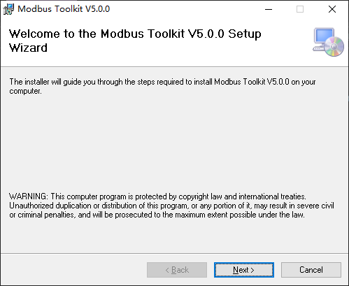
Picture 2 -1. Installation Wizard
Windows Firewall settings
For the first time, as TCP/UDP Server“open”When,Windows will prompt “Security Center Alert”. As shown in the figure 2-2 shown:
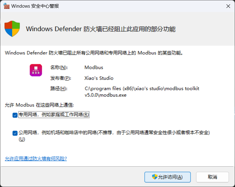
Picture 2 -2. Windows Security Center Alert
Please“Private Network”and“Public network”After selecting all options, click“Allow access”.
Features
Communication Protocol
Support all Modbus Standard Protocol:
◼ Modbus RTU
◼ Modbus ASCII
◼ Modbus TCP/IP
- Free / “Freedom”agreement (Only available on the main site/client) : for support Modbus Outside of it“Free mouth”Communication and not provided by this application Modbus Public Function Code, Modbus User defined function code.
Connect
- Except Modbus Standard connection method (Serial Port and TCP/IP) outside, Expanded UDP/IP Connect;
- Regarding TCP/IP and UDP/IP Connect, Support all the above agreements;
- Regarding Serial Port Connect, Only supports Modbus RTU , Modbus ASCII and Free agreement.
Can work as different communication roles
- Connect to"Serial Port"It can work as a master station or a slave station respectively;
- Connect to"TCP/IP"or"UDP/IP"Can work separately as a client or server at all times.
User set memory function
- Automatically save user made settings modifications, When running again, the user environment will be restored;
- Given“Restore default settings”button, Used to restore all settings parameters to factory values.
Developer Utility Tools
- Modbus RTU message, Modbus ASCII Messages and Modbus TCP/IP Mutual conversion between messages, Automatically calculate checksum CRC/LRC;
- “Message address”and“Device address”Mutual conversion between;
- Decimal and hexadecimal formats for different data types, Conversion between binary formats;
- ASCII Code Comparison Table;
- this machine IP address;
- Local serial port device.
Set parameter verification function
When modifying various setting parameters, Validate the validity of the input parameters according to the specifications.
- If the input parameters are illegal, An error message will pop up above the parameter;
- If the input parameters are valid but not secure, Warning only in the top status bar;
- When at least one parameter is illegal, it will be prohibited“Connect”/“Start”.
Example of parameter verification as shown in the figure 3-1 shown:
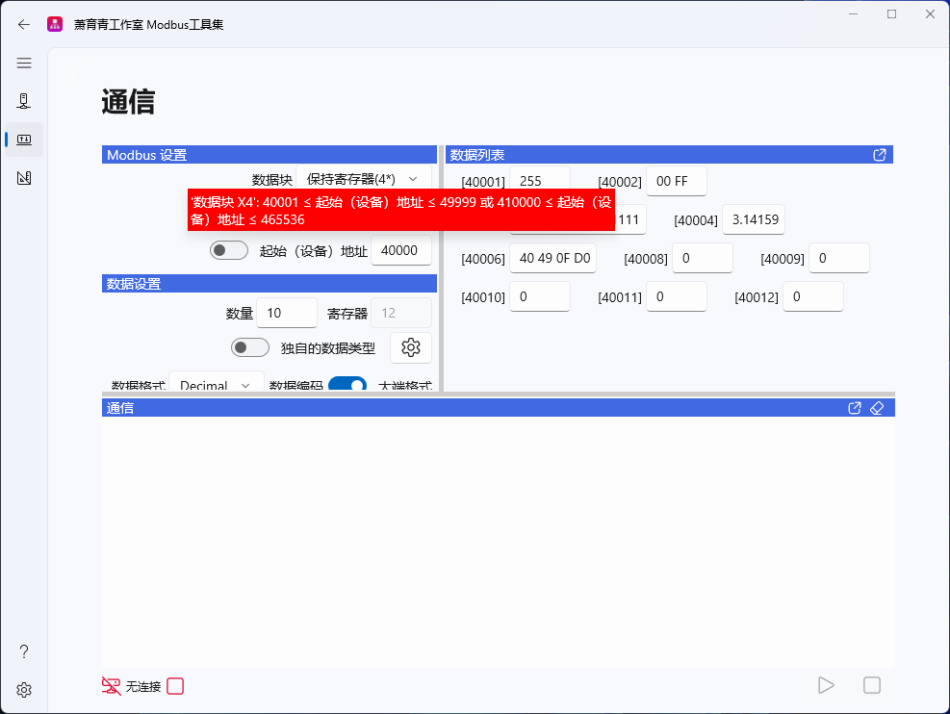
Picture 3 -1. Parameter verification example
Personalized interface settings
Allow personalized settings for the interface of the application, And automatically save the set parameters.
- Application theme;
- The interface language of the application;
- Window size of the application.
Page and Navigation
This application adopts a page based navigation system, The interface is intuitive and clear. As shown in the figure 4-1 shown:
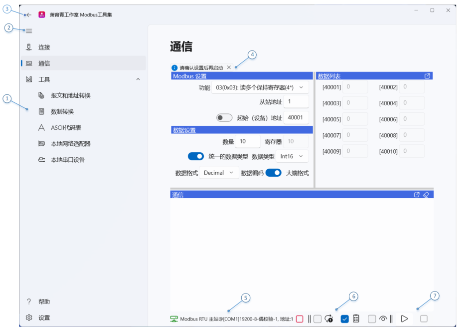
among which:
① navigation bar: Contains navigation buttons linking to various pages, Used to navigate to various pages;
②“hamburger” (Hamburger) button, Used to expand/collapse the navigation bar;
③Back button, Used to return to the previous page;
④ Information Bar: Display various alarm messages;
⑤ status bar: Display the current connection status and running status
- Connection status indication: – Connected, – Not connected;
- Protocol instructions: Modbus RTU / Modbus ASCII / Modbus TCP/IP;
- Run role indication:
➢ Regarding Modbus RTU /Modbus ASCII agreement, Role as master/slave;
➢ Regarding Modbus TCP/IP agreement, Role as client/server.
- Communication node indication:
➢ Regarding Serial Port Connection is always@, Communication nodes are always local serial devices;
➢ Regarding TCP/IP and UDP/IP Connect, When the role is a server, the indication is@, The communication node is local
Network endpoint (IP Address and Port Number) ; When the role is a client, the indication is , The communication node is
Remote network endpoint (IP Address and Port Number) .
- Communication node parameters:
➢ Regarding Serial Port Connection indication: [Communication Port] Baud Rate - Data Bit - Check Bit - Stop Bit.
for example: [COM1]19200-8-even parity-1;
➢ Regarding TCP/IP and UDP/IP Connection indication: Connect[IP address]:port number.
for example: TCP/IP [192.168.0.104]:502.
- Station address/unit identification indication, for example: address: 1;
- Operation status indication: — Stop; — Start
⑥ Communication Options Bar (Visible only when the running role is master/client) : Used to set various communication options, See Tong for details
Letter page chapter;
⑦ Action Button: See the connection page/communication page chapter for details.
When placing the mouse over each button, An automatic prompt message will pop up.
Link page
The connection page is used to set the connection method, Communication Protocol, Running roles and connection parameters. As shown in the figure 4-2 shown:
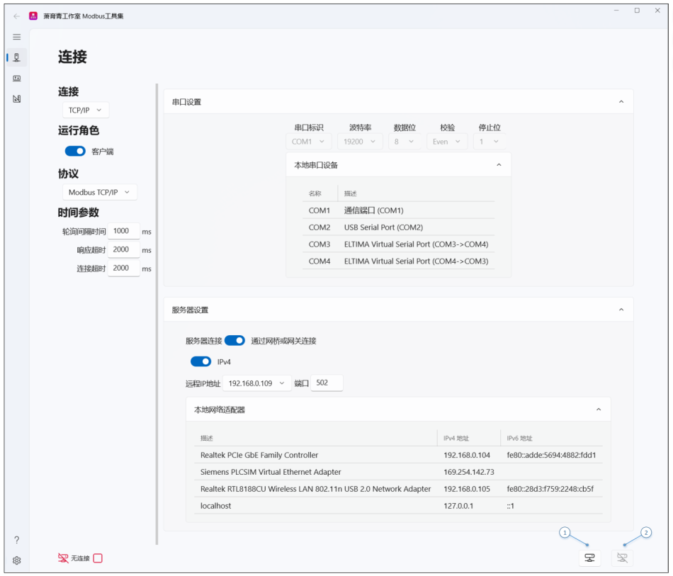
among which:
① (Main station or client) Connect/ (From station or server) Open button;
② (Windows 11) / (Windows 10) : (Main station or client) disconnect/ (From station or server) Close button.
Attention: Except“time parameter”Outside,Other settings can only be changed when the connection is disconnected/closed!
Connect
Select the connection method from the drop-down menu.
- Serial Port
When the running role is a slave station, Only one main station is allowed to access at a time! If multiple master stations communicate with the same slave station simultaneously, it may result in errors!
- TCP/IP
When the running role is a server, The number of clients that can be processed simultaneously is determined by“Maximum number of clients” (see details“server setting”a section) Settings;
- UDP/IP
When the running role is a server, There is no limit to the number of clients that can be processed simultaneously (Restricted only by system resources) .
Run Role
- Connect to"Serial Port"It can work as a master station or a slave station respectively
Allow opening multiple instances (Execute this application multiple times) , Work simultaneously as a master or slave station respectively.
- Connect to"TCP/IP"or"UDP/IP"Can work separately as a client or server at all times
◼ Allow opening multiple instances (Execute this application multiple times) , Work simultaneously as a client or server
Make;
◼ When opening multiple instances, One client can access multiple (Local or network) Server, A server
Can serve multiple (Local or network) client.
agreement
Select communication protocol from the dropdown menu.
- When“Connect”for“TCP/IP”or“UDP/IP”When,The available options are:
◼ Modbus RTU;
◼ Modbus ASCII;
◼ Modbus TCP/IP.
- When“Connect”for“Serial Port”When,The available options are:
◼ Modbus RTU;
◼ Modbus ASCII.
- When“Run Role”for“main site” / “client”When,Optional increase“Free” (Free Agreement)
◼ Free protocols are used to support applications that are not provided by this application Modbus Public Function Code, Modbus user-defined
Function code and Modbus Outside of it“Free mouth”Communication;
◼ Under the free agreement, Users need to manually input“Request message”, And this application does not perform any verification;
◼ Under the free agreement, Only display received/sent messages, Do not do any other processing.
time parameter
All time parameters in this section are measured in milliseconds (ms) .
- Polling interval time (Only for client/main site use)
The delay time between the completion of a query by the client/main station and the next request sent.
100 ≤ polling time ≤ 2147483647.
- Response timeout (Only for client/main site use)
The maximum time for the client/master station to wait for a response from the server/slave station after sending a request. If no response is received within this time frame
It should be considered as a communication failure, Prompt alarm information.
1000 ≤ Response timeout ≤ 2147483647.
Attention
When the client/master station queries a large number of parameters or communication rates (Baud rate/internet speed) At lower levels, Possible occurrence“super
time”alarm! Can be appropriately increased“Response timeout”SolveBut“Response timeout”If the application is too large, it will not be able to monitor
Possible communication failure.
- Connection timed out (For use only TCP/IP Connect)
◼ Regarding TCP client: The maximum time to wait for server confirmation after initiating a connection. If not within this time frame
Upon receiving confirmation from the server, it is considered a communication failure and an alarm message is prompted.
500 ≤ (client) Connection timed out ≤ 2147483647.
◼ Regarding TCP Server: After the client connection is established, Periodically receive requests from clients. Connect to Super
timeTo query the cycle time of the client sending requests, Used to determine the client's“Activity”Status. If waiting
If the time for the client to send the request exceeds the connection timeout, the client will be marked as“inactive”. Usually, connected
The timeout should be greater than the polling interval of the client.
1000 ≤ (Server) Connection timed out ≤ 2147483647.
Serial Port Settings
When the computer does not have a serial port and needs to communicate with a serial link, Connectable“USB-RS232/485 transformer”To expand the serial port. When the computer does not have a serial port and requires local simulation testing, available“Virtual Serial Port”Software to expand virtual serial port.
 串口标识:仅列本地可用串口(自动识别)。

 数据位

根据 Modbus 规范,对于 Modbus RTU 协议,  数据位必须为 8;

根据 Modbus 规范,对于 Modbus ASCII 协议, 数据位必须为 7;

对于自由协议(Free),数据位可为 7 或 8。

停止位与校验

对于 Modbus RTU / Modbus ASCII 协议:

当校验为“奇/偶”时,停止位必须为 1;

当校验为“无”时, 停止位必须为 2。

对于自由协议(Free)不做限制:
Verification optional None, Odd, Even, Mark, Space;
Stop position optional: None,1 , 2 , 1.5.
本地串口设备
Provide local serial port (Including hardware serial port and virtual serial port) The identification, For convenience when multiple serial devices are installed
Choice.
Attention, Virtual serial port is only used for communication between local machine processes, Not available for communication with external devices.
server setting
服务器连接
only when“agreement”for“Modbus TCP/IP”Visible at all times, Used to set the connection method for the server.
直接连接: 服务器直接连接到网络;


通过网桥或网关连接:服务器连接到串行链路子网,并通过网桥或网关来寻址。

 IP 地址支持 IPv4  和  IPv6  寻址模式;

任何地址(作为服务器运行时)
When selected, The server will respond to all local requests IP Client requests received at the address. “Any address”display as: [0.0.0.0] (IPv4)Or [::] (IPv6) .
最大客户端数(仅用于 TCP/IP 连接且运行角色为服务器时)
TCP The maximum number of clients that the server can process simultaneously . According to device type, The value of this parameter can be obtained from 1 to 16.
When the number of connections reaches the limit for simultaneous connections and new client connection requests are received:
若存在“非活动”的客户端,则断开最先的“非活动”的客户端并接受新的客户端;

若不存在“ 非活动”的客户端,则拒绝新的客户端连接请求。

远程 IP 地址(作为客户端运行时)
Can be found in the dropdown menu“remote IP address”Type in the server you want to access IP address. Newly typed server IP The address will be automatically memorized, Reconnect the IP You can directly access the address from the dropdown menu“remote IP address”Just choose from the middle, No need to re-enter;
本地 IP 地址(作为服务器运行时)

可在下拉菜单中选择 IP 地址,“本地 IP 地址”为自动识别 。为方便在一台电脑上 同时运行服务器和客户端以测试,列表中附加了本地主机(localhost)的“回送地 址”(IPv4: [127.0.0.1]/ IPv6: [::1])。“回送地址” 为主机 IP堆栈内部的 IP 地址,主 要用于网络软件测试以及本地机进程间通信,不进行任何网络传输。

端口

根据“RFC1122”,允许的端口: 1  ≤  端口  ≤  49151;

对于  Modbus TCP/IP  协议, TCP 端口 502 是为 Modbus 通信保留的。在默认状 态下,强制监听此端口。然而,某些市售产品或应用程序可能需要另一个端口专 用于 TCP 上的 MODBUS。鉴于此,本应用也允许指定缺省端口(502)之外的端 口,仅给出警告信息;

对于  Modbus RTU  和  Modbus ASCII  协议,为安全计, 建议  2000   ≤  端口  ≤ 5000,为了适应某些市售产品或应用的需要,本应用也允许指定此范围之外的端 口,仅给出警告信息。

本地网络适配器
Provide local network adapter (Hardware adapters and virtual adapters) Identification and IP address (including“Loopback Address ”) . Attention, The virtual network adapter is only used for communication between local machine processes, Not available for communication with external devices.
Communication page
The communication page is used for Modbus Communication parameter settings, Reading and writing of communication data and display of communication messages.
 采用了“分割窗口”布局, 通过拖动分割条, 可以改变各分栏的尺寸, 以适应不同的 需求;

 可将“数据列表”和“通信”栏弹出到独立窗口,以方便对照观察。
The communication page is shown in the figure 4-3 And the picture 4-4 shown:
Picture 4 -3. Communication page: Server/Slave
8
6
1
3
2
4
12
11
10
9
7
5
Picture 4 -4. Communication page: Client/Main Station
among which:
①
: “single time”checkbox, When selecting, click the start button to initiate only one query conversation;
②
: “response data”checkbox, When selected, in“Communication”Output the data obtained by parsing the response message in the column;
③
: “Preview”checkbox, When selected, in“Request message”Display by“MODBUS Settings”Generated request message; ④
: Start button When(Link page) Effective when connected/opened correctly, Used to initiate communication conversations;
⑤ 0: Stop button , Valid when communication dialogue has been initiated, Used to terminate communication conversations; ⑥
: “Request message”Erase button, Clear“Request message”The current content;
⑦ C: “Request message”Refresh button, Click based on the current situation“ MODBUS Settings”Refresh request message; ⑧
: “Communication”Popup Button , will“Communication”Pop up the bar to a separate window, Pop up window as shown in the figure 4-5 shown; ⑨
: “Communication”Erase button, Clear“Communication”The current content, And reset the message count;
⑩ Horizontal dividing strip: Drag it to change the size of the horizontal column;
⑪
: “data list”Popup Button , will“data list”Pop up the bar to a separate window, Pop up window as shown in the figure 4-6 As shown;
⑫ Vertical dividing strip: Drag it to change the size of the vertical column.
Picture 4 -5. “Communication”pop-up window
Picture 4 -6. “data list”pop-up window
Modbus Settings
Attention: When the running role is“main site”/“client”When,Some parameters can only be changed when the communication conversation is not started!
- Function
The running role is“main site”/“client”When used for selection“Function”. supported Modbus Functions as shown in the table 4-1 shown:
| function code | Description |
|---|---|
| 01 (0x01) | Read multiple coils (0*) |
| 02 (0x02) | Read multiple discrete inputs (1*) |
| 03 (0x03) | Read multiple hold registers (4*) |
| 04 (0x04) | Read multiple input registers (3*) |
| 05 (0x05) | Write a single coil (0*) |
| 06 (0x06) | Write a single hold register (4*) |
| 15 (0x0F) | Write multiple coils (0*) |
| 16 (0x10) | Write multiple hold registers (4*) |
⚫ data block
The running role is“slave”/“Server”When used to select data blocks. The data block options are shown in the table 4-2 shown:
| data block | Description |
|---|---|
| coil (0*) | Coil |
| Discrete Input (1*) | Discrete Input |
| holding register (4*) | Holding Register |
| input register (3*) | Input Register |
table 4-1. supported Modbus Function
The running role is“slave”/“Server”When used to select data blocks . The data block options are shown in the table 4-2 shown:
data block
coil (0) Discrete Input (1)
holding register (4) input register (3)
table 4-2. Modbus Standard data block
从站地址
When“agreement”for“Modbus RTU”or“Modbus ASCII” (Usually connected as“Serial Port”)When,The slave address is used to set the identity of the slave on the serial link.
运行角色为“从站”时为本站的唯一标识。从站地址取值范围: 1  ≤(本地)从站地址  ≤  247;

运行角色为“主站”时用于指定对其发送请求的从站地址: 0  ≤(远程)从站地址  ≤  247。
among which, slave address 0 dedicated to“broadcast mode”That is, The master station sends requests to all slave stations. The slave station did not respond to the broadcast request from the master station and returned it, Broadcast requests are generally used to write commands.
单元标识
When“agreement”for“Modbus TCP/IP” (Usually connected as“TCP/IP”)When,Unit identification is used for Modbus+ or Modbus Routing purpose when addressing devices on a serial line subnet. under these circumstances, Unit identification carrying remote devices Modbus From address . Modbus TCP/IP Communication structure as shown in the diagram 4-7 shown.
如果 Modbus 服务器连接到 Modbus+或 Modbus 串行链路子网,并通过网桥 或网关来寻址,单元标识对识别连接到网桥或网关后的子网的从站设备是必需 的。单元标识采用有效的 Modbus 从站地址(1 … 247)。目的 IP 地址识别网 桥或网关, 而网桥或网关则使用单元标识将请求转交给相应的从站设备;

对于直接连接到 TCP/IP 或 UDP/IP 网络上的服务器,以“IP 地址”寻址服务器, 因此单元标识是无用的。建议单元标识不要使用有效的  Modbus  从站地址
(1 … 247) . Otherwise, Reassignment in automation systems IP In the case of an address, Using a valid slave address may cause trouble due to poor routing of the gateway! Invalid slave address should be used (0 or 248 … 255) , The gateway will simply ignore Modbus PDU, Without causing any trouble. recommend adoption 255 (0xFF)Or 0 (0x00) as“element ID”Invalid value for.
Picture 4 -7. Modbus TCP/IP Communication structure
start (message) Address and starting point (Device) address
数据起始地址支持双格式地址: 报文(协议) 地址和设备地址;

选中“起始报文地址”时,可设置“起始报文地址”,自动同步映射到“起始设备地 址”,“数据列表”按报文地址显示;

选中“起始设备地址”时,可设置“起始设备地址”,自动同步映射到“起始报文地 址”,“数据列表”按设备地址显示;

请求报文中的数据起始地址均为报文(协议) 地址;

报文(协议)地址范围对于所有数据块均为: 0 ~ 65535;

设备地址支持“5 位寻址”(对应报文地址 0~9998)/ “6 位寻址”(对应报文地 址 9999~65535),其范围因数据块不同。 如表 4-3 所示:
Of course., The following is the table corresponding to the data block and its 5-bit and 6-bit addressing ranges you provided:
| data block | 5 Bit addressing range | 6 Bit addressing range |
|---|---|---|
| coil (0*) | 1 ~ 9999 | 10000 ~ 65536 |
| Discrete Input (1*) | 10001 ~ 19999 | 110000 ~ 165536 |
| holding register (4*) | 40001 ~ 49999 | 410000 ~ 465536 |
| input register (3*) | 30001 ~ 39999 | 310000 ~ 365536 |
Data Settings
1) Coil or discrete input data settings
When selecting a function/data block as a coil (0) Or discrete input (1) When visiting, Data settings are shown in the figure 4-8 shown:
Picture 4 -8. Data settings for coil or discrete input access
数量
Number of coils or discrete inputs queried/responded to.
字节数
read-only. For the main station/client, The actual number of bytes sent; For slave/server, The actual number of bytes occupied by the data block.
2) Maintain register or input register data settings
When selecting a function/data block as a hold register (4) Or input register (3) When visiting, Data settings are shown in the figure 4-9 As shown:
Picture 4 -9. Maintain data settings for accessing registers or input registers
数量
Query/Response“data ”the quantity of.
Attention
For register read and write functions (data block: 3* / 4*) , The settings set here “data volume”Different from reality Modbus In the message“number of registers ”!
The number of registers occupied by a data varies depending on the data type (See table for details. 4-5) .
对于主站/客户端,查询的最大(报文)数量因功能而不同,如表 4-4 所示:
Of course., Here is what you have providedModbusfunction code, Table of data blocks and maximum query message quantity:
| function code | data block | Maximum number of query messages |
|---|---|---|
| 01 (0x01) | coil (0*) | 2000 coil |
| 02 (0x02) | Discrete Input (1*) | 2000 Input |
| 03 (0x03) | holding register (4*) | 125 register |
| 04 (0x04) | input register (3*) | 125 register |
| 05 (0x05) | coil (0*) | 1 coil |
| 06 (0x06) | holding register (4*) | 1 register |
| 15 (0x0F) | coil (0*) | 1968 coil |
| 16(0x10) | holding register (4*) | 123 register |
对于从站/服务器,数量最大值 = 65535。
Attention
Whether it's the master/client or the slave/server, All should meet the requirements: starting address + quantity ≤ Address Range
寄存器
read-onlyFrom“data”The actual number of registers determined by their quantity and data type.
统一的数据类型
The data types of all data items, The data format and encoding are the same, by“Data Settings”Directly unify settings.
Unique data type
Can define the data types of each data item in the data list separately, Data format and encoding. click a button
Pop up register data setting window for individual settings, As shown in the figure 4-10 shown.
Attention, When the main station/client selects“Read register”Function (03/04)When, In the register data setting window “numerical value”Read-only!
Picture 4 -10. Register Data Setting Window
Select the data type for communication exchange data. The supported data types are shown in the table 4-5 shown:
| data type | Instructions | Length, byte | Occupy register |
|---|---|---|---|
| Int16 | With symbols 16 short | 2 | 1 |
| UInt16 | unsigned 16 short | 2 | 1 |
| Int32 | With symbols 32 short | 4 | 2 |
| UInt32 | unsigned 32 short | 4 | 2 |
| Int64 | With symbols 64 short | 8 | 4 |
| UInt64 | unsigned 64 short | 8 | 4 |
| Single | 32 Bit floating point type | 4 | 2 |
| Double | 64 Bit floating point type | 8 | 4 |
table 4-5. Supported data types
Regarding“Write a single hold register”Function (06) , Only allowed to occupy 1 A register (Length 2 byte) The data type of.
数据格式
Select the display format for communication exchange data. The supported data formats are shown in the table 4-6 shown:
| data format | Instructions | Example (130, Int16, big endian ) |
|---|---|---|
| Decimal | decimal | 130 |
| Hex | hexadecimal | 00 82 |
| Binary | binary | 00000000 10000010 |
数据编码

支持 2 种数据编码
big endian (Big-endian, First, transmit the most significant byte) ;
Small format (Little-endian, First, transmit the least significant byte) .
根据《基于 Modbus 协议的工业自动化网络规范  GB-T19582.1-2008》,对于 地址和数据,Modbus 使用“大端格式”,即,当传送的数据大于一个字节时, 首先传送最高有效字节;

为了适应某些市售产品或应用的数据编码为“小端格式”的场合, 本应用允许选 择“数据编码”为“小端格式”以正确解析响应数据;

数据编码仅影响寄存器数值的显示,  不影响线圈/离散输入数据、"数量"和"地 址"。
“data list”and“response data”Will be selected according to“data type” , “data format”and“Data encoding”display.
data list
Communication exchange data list, Used to set output data/display input data.
 项数由“MODBUS 设置”中的“数量”设定;

 显示格式: [地址]               (如: [40003]                 )。 其中:

[地址]由“MODBUS 设置”中的“起始(报文)地址”/“起始(设备)地址”选项设 定;

              的显示由“MODBUS 设置”中的“数据类型”,“数据格式”和“数据编码”设 定。


 设置数据: 以鼠标点击              ,即可直接键入。。 作为主站/客户端运行时:
numerical value
 当选择“读”功能(功能码  = 1 ,2,3,4) 时, 数据列表为只读;

 当选择“Free”(自由协议) 时,不显示“数据列表”。
Communication
Used for communication conversations (message, response data, Communication status) The display.
- Connection information (Only when the connection is TCP/IP or UDP/IP Time effective)
◼ format: “Remote: [IP address: port number], Local: [IP address: port number]”;
◼ For servers:
◆ Due to the fact that a server can serve multiple clients, Display whenever the sender of the received message changes;
◆ When selected“Any address”When,IP address = “0.0.0.0” (IPv4) / “::” (IPv6) .
◼ For the client: only when“Start”Time display.
- Format of the message sent: “xxxx-Txd: HH HH …”. “xxxx”: Counting of Conversations (Serial number) , “Txd”: Sender ID, “HH HH …”: Hexadecimal format message;
- Received message format: “xxxx-Rxd: HH HH …”. “xxxx”: Counting of Conversations (Serial number) , “Rxd”: Receive identification, “HH HH …”: Hexadecimal format message;
- Number of response data/sending registers: “xxxx-Val / Qty: DD,DD, …”, “xxxx”: Counting of Conversations (Serial number) , “Val”: Response data identification, “Qty”: Send register number identifier, “DD,DD, …”: Response data in decimal format/number of sending registers;
- Modbus Exception Response: “xxxx-Err: Exception message”. Abnormal information is related to the abnormal response messages returned by the slave/server;
- Click“Communication”The erase button can be cleared at any time“Communication”The current content, And reset the message count.
Request message
When choosing“Free” (Free Agreement) Or select“Preview”Visible when selecting options.
- Choice“Free” (Free Agreement)When,Used for manually inputting request messages (Do not perform any verification) ;
- Select“Preview”When selecting options, for“Preview”from“Modbus Settings”Generated request message;
- Click“Request message”The erase button can be used to clear“Request message”The current content;
- Click“Request message”Refresh button based on current“MODBUS Settings”Refresh request message.
Free protocol interface
Free protocols are used to support applications that are not provided by this application Modbus Public Function Code, Modbus User defined function codes and Modbus Outside of it“Free mouth”Communication.
Users need to manually input“Request message”, This application does not perform any validation except for the input format.
When“Run Role”for“main site”/“client”And choose“Free” (Free Agreement)When, Do not display“data list” , “ ModbusSettings”and“Data Settings”Column. Page as shown in the picture 4-11 shown:
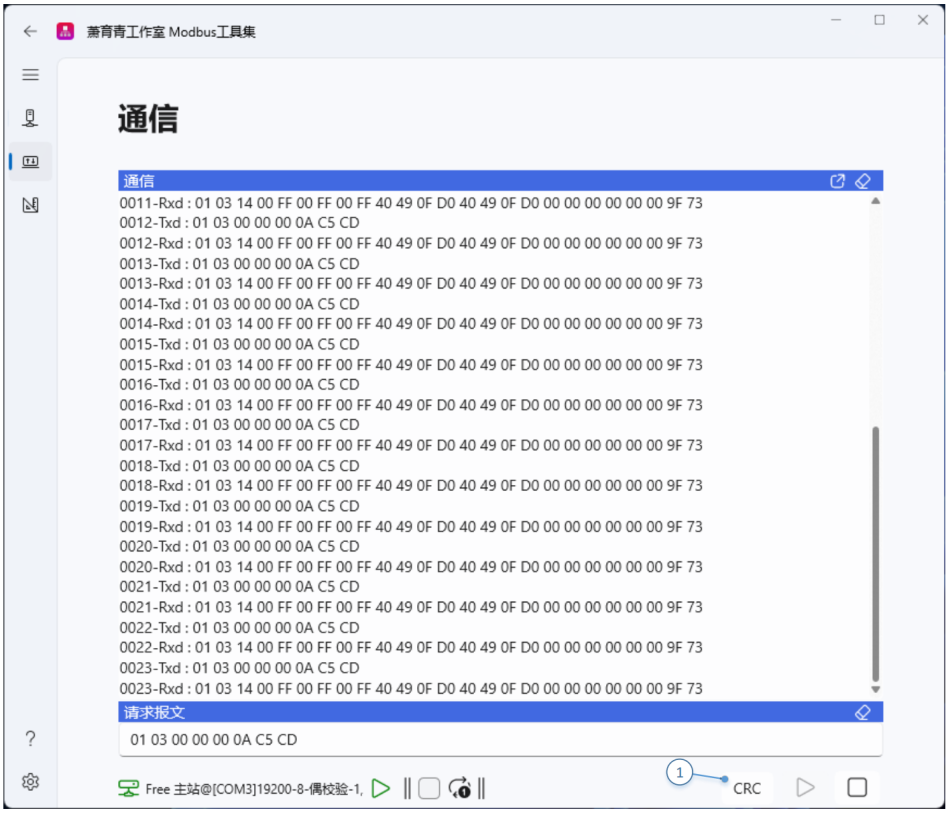
Picture 4 -11. Free protocol interface
among which:
① : Towards“Request message”Add CRC Verification code button. When clicking this button, Based on the current situation“Request message”Automatic Generation CRC Verification code and attached“Request message”end.
Tool page
Provides various developer utility tools.
Message and Address Translation
As shown in the figure 4-12 shown:
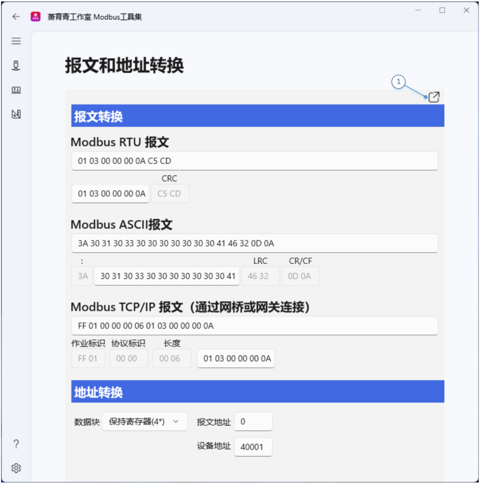
among which:
①Popup Button , Can pop up to a separate window.
- Modbus RTU message, Modbus ASCII Messages and Modbus TCP/IP Mutual conversion between messages
Each protocol provides 2 Message in various formats:
◼ Complete message (ADU/Application data unit) ;
◼ Partial message: Only include address (element ID) Protocol Data Unit(PDU). automatic calculation CRC/LRC Wait, wait,
And automatically fill in the first and last fields.
After the message input is completed, it must be pressed Enter Key to submit.
◼ If the input message is valid, All other messages will be updated synchronously;
◼ If the input message is illegal, An error prompt will pop up above it.
- Mutual conversion between message address and device address
drop-down menu“data block”Used to select data addressing space.
◼ in“Message address”Enter the address in the middle, If the input address is valid, “Device address”Synchronize updates;
◼ in“Device address”Enter the address in the middle, If the input address is valid, “Message address”Synchronize updates;
◼ If the input address is illegal, An error prompt will pop up above it.
Number system conversion
Decimal and hexadecimal formats for numerical values of different data types, Conversion between binary formats . As shown in the figure 4-13 As shown:
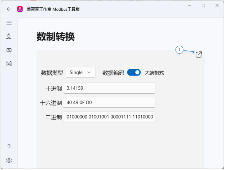
Picture 4 -13. Number system conversion
among which:
① Popup Button , Can pop up to a separate window.
| data type | Instructions | Length, byte |
|---|---|---|
| SByte | With symbols 8 short | 1 |
| Byte | unsigned 8 short | 1 |
| Int16 | With symbols 16 short | 2 |
| UInt16 | unsigned 16 short | 2 |
| Int32 | With symbols 32 short | 4 |
| UInt32 | unsigned 32 short | 4 |
| Int64 | With symbols 64 short | 8 |
| UInt64 | unsigned 64 short | 8 |
| Single | 32 Bit floating point type | 4 |
| Double | 64 Bit floating point type | 8 |
- “decimal”, “hexadecimal”and“binary”Fields are used to input numerical values
◼ If the input value is valid, All other fields will be updated synchronously;
◼ If the input value is illegal, An error prompt will pop up above it.
- Switch“Data encoding”When,All fields will automatically change.
ASCII code table
Provide standards ASCII code table . As shown in the figure 4-14 shown:
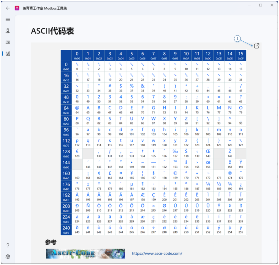
among which,
① Popup Button , Can pop up to a separate window.
Local network adapter
Provide the identification of all local network adapters and IP address. As shown in the figure 4-15 shown:
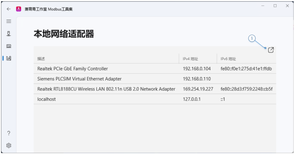
among which,
① Popup Button , Can pop up to a separate window.
Local serial port device
Local serial port (Including virtual serial port) The identification. As shown in the figure 4-16 shown:
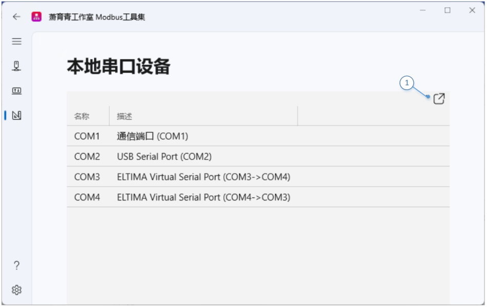
among which,
① Popup Button , Can pop up to a separate window.
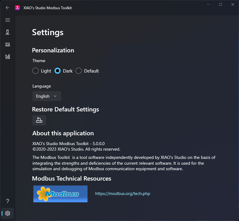
Settings Page
The settings page is used to personalize the theme of this application, Language and restore factory default settings parameters. As shown in the figure 4-17 shown:

Personalization
- “Theme”: Set the theme for this application. Select“Default”When,The theme of this application will be related to the operating system“WindowsSettings”/“Personalization”/“Theme”consistent;
- “Language”: Set the language for this application. Supported Languages: Chinese (Simplified Chinese) , English, French and German.
Personalized example as shown in the figure 4-18 shown.
Restore default settings
Click the button to restore all settings parameters of this application to their factory default settings.
Attention: Allow operation only when the connection is disconnected.



好
感谢分享
学习!
学习下
????
neverstop
试试看工业用方不方便
测试
学习学习,非常需要
试一下看看怎么样?
66666
航空科技急急急
试一下
不就是个工具软件吗 弄得这么复杂 太拿自己当回事儿了
阿斯顿法师打发是的法师打发三大发啥打法
❤️❤️
看看
!!!
给个下载地址我试试,谢谢!
试一下看好不好用
不错不错
111
123
不知道好不好用,好用会回来好评的
Share+1
谢谢分析
好用,謝謝分享
很好!!!!!!!!!!!!!!1
,..
???