
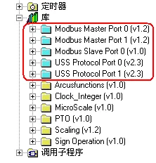
The S7-200 supports the Modbus RTU communication protocol through the following methods:
- Communication port 0 (Port 0) on the S7-200 CPU supports Modbus RTU slave mode through an instruction library.
- Communication ports 0 and 1 (Port 0 and Port 1) on the S7-200 CPU support Modbus RTU master mode through an instruction library.
RS485 half-duplex communication is implemented on the S7-200 CPU communication port, utilizing the free port function of the S7-200.
The Modbus communication protocol is implemented through the free port mode of the S7-200 CPU communication port, and can be transmitted via slow communication devices such as wireless data radios. This facilitates the formation of a simple wireless communication network between S7-200s.
For detailed information, please refer to the corresponding chapters in the "S7-200 System Manual" (version October 2002 or later).
Does the S7-200 support Modbus ASCII communication mode?
Siemens does not provide a ready-made instruction library supporting the above modes for the S7-200, and users are required to program in free port mode themselves.
Modbus RTU master
Modbus RTU master instruction library
Siemens officially launched the Modbus RTU master protocol library (Siemens standard library instructions) in Micro/WIN V4.0 SP5.
Note:
1. The function of the Modbus RTU master command library is implemented by calling pre-programmed function blocks in the user program, and this library is valid for Port 0 and Port 1. This command library sets the communication port to operate in free port mode.
2. The Modbus RTU master command library uses some user interrupt functions, and interrupts cannot be disabled in the user program when writing other programs.
3. The Modbus RTU master library has requirements for the CPU version. The CPU version must be 2.00 or 2.01 (i.e., order number 6ES721*-***23-0BA*), and S7-200 CPUs before version 1.22 (including version 1.22) are not supported.
Using the Modbus RTU master command library, it is possible to read and write digital and analog I/O and hold registers of Modbus RTU slaves.
To use the Modbus RTU master command library, the following steps must be followed:
1.Install the Siemens standard command library
2.Write a user program to call the Modbus RTU master command library as required
Program the Modbus RTU master function
Call the Modbus RTU master initialization and control subroutine
Use SM0.0 to call MBUS_CTRL to complete the initialization of the master and start its function control:
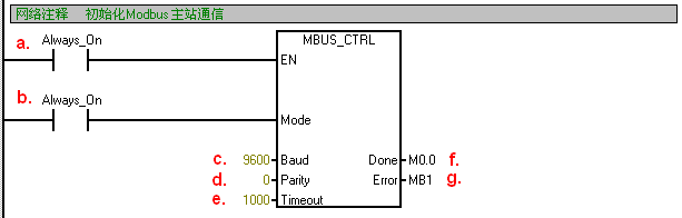
The meanings of each parameter are as follows:
a. EN Enable: It must be ensured that each scanning cycle is enabled (using SM0.0).
b. Mode: When set to 1, the Modbus protocol function is enabled; when set to 0, it reverts to the system PPI protocol.
c. Baud Rate: The supported communication baud rates are 1200, 2400, 4800, 9600, 19200, 38400, 57600, and 115200.
d. Parity Check: Select the parity check method.
0 = No Parity Check
1 = Odd Parity Check
2 = Even Parity Check
e. Timeout: The time for the master station to wait for a response from the slave station, measured in milliseconds. The typical setting is 1000 milliseconds (1 second), and the allowable setting range is 1 - 32767.
Note: This value must be set sufficiently large to ensure that the slave station has time to respond.
f. Done: The initialization is complete, and this bit will automatically be set to 1. This bit can be used to initiate MBUS_MSG read and write operations (see example routine).
g. Error: The initialization error code (only valid when the Done bit is 1):
0 = No error
1 = Check selection illegal
2 = Baud rate selection illegal
3 = Mode selection illegal
Call the Modbus RTU master read-write subroutine MBUS_MSG to send a Modbus request;
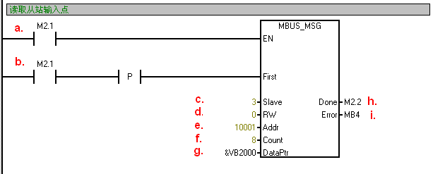
The meanings of each parameter are as follows:
a. EN Enable: Only one read-write function (i.e., MBUS_MSG) can be enabled at the same time
Note: It is recommended that each read-write function (i.e., MBUS_MSG) be activated using the Done bit of the previous MBUS_MSG instruction to ensure that all read-write instructions are executed in a circular manner (see routine).
b. First read-write request bit: Each new read-write request must be triggered using a pulse
c. Slave address: Selectable range 1 - 247
d. RW slave address: 0 = Read, 1 = Write
Note:
1. Switching value output and holding registers support read and write functions
2. Switching value input and analog input only support read function
e. Addr Data address for reading and writing slave stations:
Select the data type for reading and writing
00001 to 0xxxx - Switching value output
10001 to 1xxxx - Switching value input
30001 to 3xxxx - Analog input
40001 to 4xxxx - Holding registers
f. Count Number of data The number of data (bits or words) communicated
Note: The maximum amount of data that can be read/written by a Modbus master is 120 words (referring to each MBUS_MSG instruction)
g. DataPtr Data pointer: 1. If it is a read instruction, the read data is placed in this data area
If it is a write command, the data to be written should be placed in this data area
h. Done bit: The read-write function completion bit
i. Error code: The error code is only valid when the Done bit is 1
0 = No error
1 = Response check error
2 = Not used
3 = Receive timeout (no response from the slave)
4 = Request parameter error (slave address, Modbus address, count, RW)
5 = Modbus/free port not enabled
6 = Modbus is busy with other requests
7 = Response error (the response is not the requested operation)
8 = Response CRC check sum error
-
101 = The slave does not support the requested function
102 = The slave does not support the data address
103 = The slave does not support this data type
104 = Slave device failure
105 = The slave has received the message, but the response is delayed
106 = The slave is busy and has rejected the message
107 = The slave has rejected the message
108 = Slave memory parity error
Common errors:
If multiple MBUS_MSG instructions are enabled simultaneously, it may cause error 6
Sometimes, error 6 may also occur when the library storage area is reused by other parts of the program
Setting the delay parameter of the slave too long may cause error 3 on the master
A slave station experiencing power loss or non-operation, or a network failure, can result in a master station error code 3.
Allocate storage area (Library Memory) for library instructions in the CPU's V data area.
The Modbus Master instruction library requires a global V storage area of 284 bytes.
1.3 About Modbus RTU Master Protocol and Addresses
This is the official standard library instruction description document from Siemens.
Switching between Modbus RTU Master Protocol and PPI Protocol:
The Modbus RTU Master Protocol instruction library enables the communication port to operate in free port mode, during which it cannot communicate with Micro/WIN software. To switch back to PPI Protocol, you can:
- Set the Mode input of the MBUS_CTRL instruction to logic "0".
- Set the CPU's enable mode selection switch to the STOP position.
Execution time of the Modbus RTU Master Protocol library:
The MBUS_CTRL instruction of the Modbus RTU Master Protocol library does not require a long execution time. MBUS_ requires 1.11 ms for initialization and only occupies 0.41 ms in each subsequent scanning cycle.
Calling the MBUS_MSG subroutine will increase processing time. Most of the time is spent on CRC check calculations. Each read or write of a word of data requires 1.85 ms of scanning time. In the case of the most data (reading or writing 120 words of data), the scanning time will increase by approximately 222 ms. The time consumed for read operations is mainly on receiving data; the time consumed for write operations is mainly on sending data.
Modbus Address
Typically, a Modbus address consists of 5 digits, including the initial data type code and the subsequent offset address. The Modbus Master protocol library maps standard Modbus addresses to so-called Modbus function numbers for reading and writing data from slave devices. The Modbus Master protocol library supports the following addresses:
- 00001 - 09999: Digital Output (Coil)
- 10001 - 19999: Digital Input (Contact)
- 30001 - 39999: Input Data Register (usually Analog Input)
- 40001 - 49999: Data Holding Register
Functions Supported by the Modbus Master Protocol Library
To support the reading and writing of the above Modbus addresses, the Modbus Master protocol library requires the following functions to be supported by the slave devices:
Table 1. Functions Required to be Supported by Slave Devices
| Modbus Address | Read/Write | Functions Required to be Supported by Modbus Slave Devices |
| 00001 - 09999 Digital Output | Read | Function Code 1 |
| 00001 - 09999 Digital Output | Write | Function Code 5: Write Single Output Point Function Code 15: Write Multiple Output Points |
| 10001 - 19999 Digital Input | Read | Function Code 2 |
| 10001 - 19999 Digital Input | Write | - |
| 30001 - 39999 Input Registers | Read | Function Code 4 |
| 30001 - 39999 Input Registers | Write | - |
| 40001 - 49999 Hold Registers | Read | Function Code 3 |
| 40001 - 49999 Hold Registers | Write | Function 6: Write Single Register Unit Function 16: Write Multiple Register Units |
Mapping of Modbus Addresses and S7-200 Memory Area Addresses
When the S7-200 communicates through the Modbus Master and Slave protocol libraries, the mapping relationship between Modbus addresses and S7-200 memory area addresses is similar.
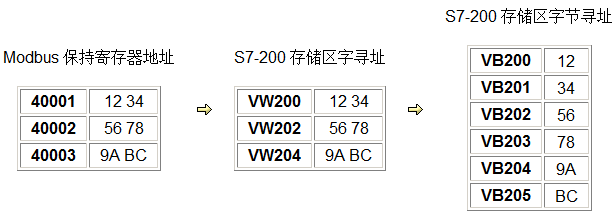
Modbus Digital Address Mapping Example:
Bit addresses (0xxxx and 1xxxx) are always packaged and read/written in bytes. The least significant bit in the first byte corresponds to the starting address of the Modbus address. As shown in the figure below:
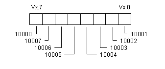
Figure 4. Digital Address Mapping Example
1.4 Modbus RTU Master Routine
To better understand the programming of a Modbus master, refer to the following routine.
Example Program 1: Polling execution with multiple MBUS_MSG instructions,
Note
- 1. This routine is saved using Micro/WIN V4.0 SP5.
- 2. This routine only accesses one slave station. If accessing different slave stations, it can be achieved by changing the slave station address.
 Modbus RTU Master Instruction Library Application Routine
Example Program 2: Repeatedly activating a single MBUS_MSG instruction:
Modbus RTU Master Indexing Method Polling Access Application Routine
 Note:The author and owner of this instruction library/program bear no responsibility for the functionality and compatibility of the software. The use of this software is entirely at the user's own risk. As it is provided free of charge, no warranties, error corrections, or hotline support are provided, and users are not required to contact Siemens Technical Support and Services for this.
1.5 Frequently Asked Questions about Modbus RTU Master Station
 Does the Modbus RTU Master Station library have requirements for the CPU version, and why do I encounter four errors when compiling the example program?
Yes, the Modbus RTU Master Station library does have requirements for the CPU version. The CPU version must be 2.00 or 2.01 (i.e., order number 6ES721*-***23-0BA*). S7-200 CPUs before version 1.22 (including version 1.22) are not supported.
How can I monitor the CPU through the same communication port after starting the Modbus instruction library?
The Modbus instruction library uses the CPU's free port communication function. Communication ports operating in free port mode cannot use Micro/WIN's PPI programming communication monitoring. If all communication ports are occupied, consider:
- Adding a communication module (such as EM 277, CP 243-1, EM 241, etc.) to extend a programming communication port
- Disabling free port mode by switching the mode switch on the CPU from RUN to STOP; or maintaining it in the RUN state and using a program to stop the Modbus mode of the instruction library (see instruction library application)
How to understand the difference between Modbus address and function code?
Modbus address and Modbus function code are two levels of concepts.
According to the Modbus communication protocol, Modbus data addresses use the format 0xxxx, 1xxxx, 3xxxx, and 4xxxx, representing digital output, digital input, analog input, and other data addresses, respectively.
Some devices indicate that they support the Modbus RTU communication protocol, but they also provide detailed communication frame formats for reading and writing data, including how to specify the address of the Modbus station, the type and length of data to be read or written, and so on. The data frame contains a specific byte indicating the type and address of the data being read or written by this command. The data content of this byte is known as the "function code", such as function 1 specifying the reading of the value of a single/multiple digital output points.
When using devices or software that support the Modbus protocol, what users directly set or see should be the Modbus data address. The data accessed through the Modbus address is read or written using various "functions". The function code is the underlying layer of the Modbus address. If the so-called Modbus protocol provided by one party in Modbus communication only includes function codes, it is necessary to understand the correspondence between this function number and the Modbus address.
How to access hold register addresses greater than 9999?
Typically, the range of hold register addresses in the Modbus protocol is between 40001 and 49999. This is sufficient for most applications. However, some Modbus slaves map addresses to the part of the hold register area beyond 9999.
The Modbus Master protocol library supports hold register addresses greater than 9999. The address range is 400001 to 465536. Simply assign the corresponding value to the Addr parameter when calling the MBUS_MSG subroutine, such as 416768.
The Modbus Master extended address mode only supports the hold register area and does not support other address types.
What should I do if the data format received by the S7-200 as a Modbus master is different from that of third-party devices?
The storage format of Siemens PLC data is high-order low-storage. For example, VD200 includes VW200 and VW202, where VW202 is the low word and VW200 is the high word. If the third-party device has a different data storage format from Siemens, which is low-order low-storage, the communicated data will be incorrect and needs to be converted before use.
Does the S7-200 support other protocols such as Modbus TCP?
Not supported. Neither the communication port of the S7-200 itself nor its communication expansion module supports Modbus TCP, CANopen, DeviceNet, and BACnet communication protocols.
Why does the MBUS_MSG instruction report error code 6 when the S7-200 acts as a Modbus master station?
There are primarily two reasons for the occurrence of Error 6: 1. Multiple MBUS_MSG instructions are simultaneously enabled for execution; 2. The suggested address area allocated in the Modbus library storage area overlaps with the V storage area already used in programming.
2 Modbus RTU Slave
2.1 The communication port (Port0) on the CPU supports the Modbus RTU slave communication protocol
The communication port Port0 on the S7-200 CPU can support the Modbus RTU protocol and become a Modbus RTU slave. This function is implemented through the free port communication mode of the S7-200, so it can be transmitted through slow communication devices such as wireless data radios.
 For details, please refer to the relevant chapters in the "S7-200 System Manual".
To implement Modbus RTU communication, you need programming software of STEP 7-Micro/WIN32 V3.2 or later, and you must install the STEP 7-Micro/WIN32 V3.2 Instruction Library. The Modbus RTU function is implemented through pre-programmed function blocks in the instruction library.
The Modbus RTU slave instruction library only supports the communication port 0 (Port0) on the CPU.
2.2 Basic programming steps:
Check the software version of Micro/WIN, which should be STEP 7-Micro/WIN V3.2 or later.
Check whether the Modbus RTU slave instruction library exists in the instruction tree of Micro/WIN (Figure 1), and the library should include two subprograms, MBUS_INIT and MBUS_SLAVE. If not, you must install the Instruction Library software package for Micro/WIN32 V3.2;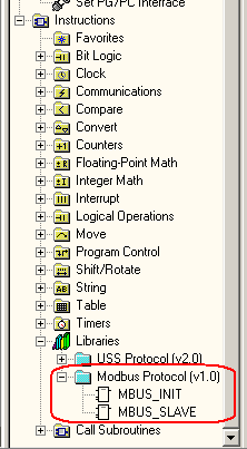
Figure 1. Library instructions in the instruction tree
During programming, use SM0.1 to call the subprogram MBUS_INIT for initialization, use SM0.0 to call MBUS_SLAVE, and specify the corresponding parameters. Detailed descriptions of the parameters can be found in the local variable table of the subprogram;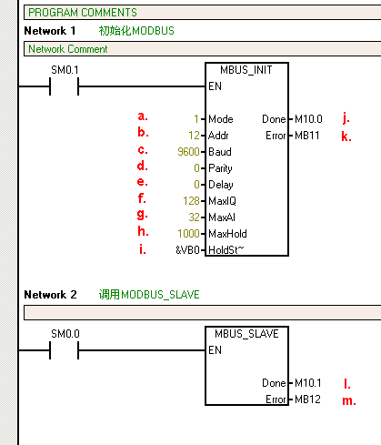
Figure 2. Calling the Modbus RTU communication instruction library
The meanings of the parameters in the figure are as follows:
- Mode selection: Start/Stop Modbus, 1=Start; 0=Stop
- Slave address: Modbus slave address, taking values from 1 to 247
- Baud rate: Optional values include 1200, 2400, 4800, 9600, 19200, 38400, 57600, and 115200
- Parity: 0=No parity; 1=Odd parity; 2=Even parity
- Delay: Additional delay between characters, with a default value of 0
- Maximum I/Q bits: The maximum number of I/O points participating in communication, with the I/O mapping area of S7-200 being 128/128, and the default value being 128
- Maximum AI word count: The maximum number of AI channels participating in communication, which can be 16 or 32
- Maximum hold register area: The V storage area word (VW) participating in communication
- Starting address of hold register area: Specified with &VBx (indirect addressing mode)
- Initialization completion flag: Set to 1 after successful initialization
- Initialization error code
- Modbus execution: Set to 1 during communication, and 0 when there is no Modbus communication activity.
- Error code: 0=no error
table1.Slave error code
| Error code | Description |
|---|---|
| 0 | No error |
| 1 | Memory area range error |
| 2 | Illegal baud rate or parity |
| 3 | Illegal slave address |
| 4 | Illegal value of Modbus parameter |
| 5 | Duplicate holding register and Modbus slave symbolic address |
| 6 | Receive check error |
| 7 | Receive CRC error |
| 8 | Illegal function request/unsupported function |
| 9 | Illegal memory area address in request |
| 10 | Slave function not enabled |
In CPU's V data areaAllocate library instruction data area (Library Memory);
If necessary, use master station software for testing.
Note:The hold register area specified by subroutine parameters HoldStart and MaxHold is allocated in the V data memory area of the S7-200 CPU. This data area cannot overlap with the library instruction data area, otherwise errors will occur during runtime and normal communication cannot be maintained. Note that the hold register area in Modbus is addressed by "word", meaning that MaxHold specifies the number of VW rather than VB.
In the example shown in Figure 2, the Modbus hold register area is specified to start from VB0 (HoldStart = VB0) and the hold registers are 1000 words (MaxHold = 1000). Since the hold registers are in units of words (two bytes), this communication buffer actually occupies a total of 2000 bytes from VB0 to VB1999. Therefore, when allocating the library instruction reserved data area, it should start from at least VB2000. Of course, the hold area does not necessarily have to start from VB0.
Note:The size of the V data storage area for the CPU you have chosen! The size of the V data storage area varies depending on the CPU model. You should select the size of the Modbus holding register area according to your needs.
 After compiling and downloading the project containing the Modbus RTU slave instruction library to the CPU, you can run some Modbus test software on the programming computer (PG/PC) to verify whether the Modbus RTU communication of the S7-200 is normal. This is useful for locating fault points. The test software connects to the CPU through the computer's serial port (RS-232) and PC/PPI cable. If necessary, the PC/PPI cable must be set to free port communication mode.
You can find similar software on some software download websites, such as ModScan32.
2.3 Modbus RTU slave address corresponds to the address of the S7-200
Modbus addresses always appear in the form of 00001, 30004, etc. The correspondence between the internal data storage area of the S7-200 and the four types of Modbus addresses (0, 1, 3, 4) is as follows:
Table 2. Modbus Address Correspondence Table
| Modbus Address | S7-200 Data Area |
|---|---|
| 00001 ~ 00128 | Q0.0 ~ Q15.7 |
| 10001 ~ 10128 | I0.0 ~ I15.7 |
| 30001 ~ 30032 | AIW0 ~ AIW62 |
| 40001 ~ 4xxxx | T ~ T + 2 * (xxxx -1) |
where T is the starting address of the buffer in S7-200, i.e., HoldStart.
If the address of the V storage area in S7-200 is known, the formula for calculating the Modbus address is as follows:
Modbus address = 40000 + (T/2+1); T is even
2.4 Modbus RTU Slave Instruction Library Supported Function Codes
The Modbus RTU Slave Instruction Library supports specific Modbus functions. The master station accessing this instruction library must comply with its requirements.
Table 3. Modbus RTU Slave Function Codes
| Function Code | The utility of the master station using the corresponding function code on this slave station |
|---|---|
| 1 | Read the status of single/multiple coils (discrete output points). Function 1 returns the ON/OFF status of any number of output points (Q). |
| 2 | Read the status of single/multiple contacts (discrete input points). Function 2 returns the ON/OFF status of any number of input points (I). |
| 3 | Read single/multiple hold registers. Function 3 returns the contents of the V storage area. Under the Modbus protocol, hold registers are "word" values, and up to 120 words of data can be read in a single request. |
| 4 | Read single/multiple input registers. Function 4 returns the analog data values of the S7-200. |
| 5 | Write to single coil (discrete output point). Function 5 is used to set the discrete output point to a specified value. This point is not forced, and the user program can overwrite the value written by the Modbus communication request. |
| 6 | Write to single hold register. Function 6 writes a value to the hold register in the V storage area of the S7-200. |
| 15 | Write to multiple coils (discrete output points). Function 15 writes the values of multiple discrete output points to the output mapping registers (Q area) of the S7-200. The address of the output points must start at a byte boundary (such as Q0.0 or Q2.0), and the number of output points must be an integer multiple of 8. This is a limitation of this Modbus RTU slave instruction library. These points are not forced, and the user program can overwrite the value written by the Modbus communication request. |
| 16 | Write to multiple hold registers. Function 16 writes multiple values to the hold registers in the V storage area of the S7-200. Up to 120 words of data can be written in a single request. |
2.5 Modbus RTU slave routine
It requires STEP 7-Micro/WIN V4.0 SP3 or later to open
2.6 Common issues of Modbus RTU slave station
What is the relationship between the network address of a Modbus slave and the CPU network address of the S7-200?
There is no relationship. Communication protocols that support network communication must have their own network addressing conventions. The address of a Modbus slave is only its address on the Modbus network, while the commonly referred S7-200 CPU address is the station address of the CPU on Siemens' PPI network. Most communication functions of the S7-200 CPU are completed through the PPI network, such as programming, network read and write communication, etc.
How to understand the difference between Modbus address and function code?
Modbus address and Modbus function code are two levels of concepts.
According to the Modbus communication protocol, the address of Modbus data uses the format of 00xxx, 10xxx, 30xxx, and 40xxx, representing digital output, digital input, analog input, and other data addresses respectively. When using the instruction library of the S7-200, there is a specific correspondence between Modbus data addresses and the I/O and data storage area addresses of the S7-200.
Some devices indicate that they support the Modbus RTU communication protocol, but also provide detailed communication frame formats for reading and writing data, including how to specify the address of the Modbus station, the type and length of data to be read and written, etc. The data frame has a specific byte indicating the type and address of the data read and written by this instruction, and the data content of this byte is the so-called "function code", such as function 1 specifying the value of a single/multiple digital output points.
When using devices or software that support the Modbus protocol, what users directly set or see should be the Modbus data address. The data accessed by the Modbus address is read and written through various "functions". The function code is the underlying layer of the Modbus address. If the so-called Modbus protocol provided by one party in Modbus communication only includes function codes, it is necessary to understand the correspondence between this function number and the Modbus address.
How to monitor the CPU through the same communication port after starting the Modbus instruction library?
The Modbus instruction library utilizes the CPU's free port communication function. Communication ports operating in free port mode cannot be monitored using Micro/WIN's PPI programming communication. If all communication ports are occupied, the following options can be considered:
- Add a communication module (such as EM 277, CP 243-1, EM 241, etc.) to expand a programming communication port
- To terminate the free-port mode, you can toggle the mode switch on the CPU from RUN to STOP; or alternatively, keep it in the RUN state and use a program to stop the Modbus mode of the instruction library (see Instruction Library Application)
Why do some HMI software applications encounter errors when using Modbus RTU to read real numbers from S7-200?
When some HMI software uses the Modbus RTU communication protocol, the way it processes real numbers (floating-point numbers) stored in data holding registers differs from Siemens' real number storage format. Siemens' PLC follows the rule of "high byte at low address, low byte at high address".
Modbus RTU always uses "words (double bytes)" as a unit, while a real number requires 4 bytes (double words) to represent. When processing, the HMI software may swap the positions of the two "words" in the holding register, causing it to fail to recognize real numbers represented in Siemens' format. If the HMI software cannot handle such real numbers, programming can be done in the S7-200 CPU to swap the high and low words of the real numbers stored in the data buffer (holding register area).
Why can some HMI software read the contents of the S7-200 as a slave station using Modbus RTU, but cannot write to it?
It is possible that this software uses Modbus function 15 (writing multiple discrete values) or similar functions (function 16). The S7-200 slave station protocol follows the convention of starting at an address boundary of a whole byte (such as Q0.0, Q2.0) and using a bit count that is a multiple of 8. If the HMI software does not strictly follow this rule, write errors may occur.
Does the S7-200 support Modbus ASCII mode?
The S7-200 can support the above mode, but there is no ready-made instruction library, requiring users to program it themselves.
Why do many errors occur after the project is compiled?
When using an instruction library, if many errors occur after compilation, it is generally because the library instruction data storage area has not been specified. Please refer torelated entries..
Can the Port1 of the S7-200 CPU support the Modbus RTU protocol?
Yes, it can. Users can implement it through programming themselves.
In the "Tips and Tricks" help document of S7-200, Tip041 is a Modbus RTU slave program that users can refer to.
Can S7-200 form a Modbus RTU communication network? How to set up the network?
S7-200 can form a Modbus RTU network based on RS-485. If the communication objects are communication ports of different standards, conversion may be required.
See:RS-485 network composition
Standard instruction library for 3STEP 7-Micro/WIN
STEP 7-Micro/WIN V4.0 and later versions come with a new instruction library internally, but it cannot be displayed and used without installing the Siemens Instruction Library software package.
To use Siemens' standard instruction library, you must first install the Siemens Instruction Library software package. After installing the Instruction Library, as long as the installed version of STEP 7-Micro/WIN is the latest, you can obtain the corresponding version of the new instruction library. Installing the Micro/WIN upgrade package (Service Pack) will also update the version of the instruction library.
Users can directly obtain the Siemens Instruction Library software installation package from below:
The latest STEP 7-Micro/WIN V4.0 SP5 version supports the following Siemens standard instruction libraries:
- USS communication protocol library:
Enables CPU communication ports Port0 and Port 1 to support USS communication control with Micro-Master 3 (MM3 series) and Micro-Master 4 (MM4 series, such as MM420, MM430, MM440, etc.), as well as SINAMICS G110 series. Through some pre-written subprograms and interrupt programs, it facilitates the control of the operation of frequency converters and the reading and writing of their parameters.
The USS instruction library for Micro/WIN V4.0 has now been optimized for Siemens' Master Drive. - Modbus RTU Slave (Slave) Communication Protocol Library:
enables CPU communication port Port0 to support Modbus RTU Slave communication functionality. - Modbus RTU Master (Master) Communication Protocol Library:

enables CPU communication ports Port 0 and Port 1 to support Modbus RTU Master communication functionality.
The above communication protocol libraries all utilize the free port communication function of the S7-200 CPU.
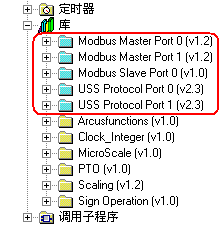
Figure 1. Siemens standard libraries are represented by light blue icons (Micro/WIN V4.0 SP5)
The STEP 7-Micro/WIN instruction library can be obtained through the following two ways:
- Install the STEP 7-Micro/WIN32 additional software package Instruction Library V1.1, order number 6ES7830-2BC00-0YX0.
- If you have already installed STEP 7-Micro/WIN32 V3.1 and Toolbox V1.0 (including TP Designer configured for TP070 and the old instruction library, order number 6ES7810-2TC00-0YX0), then installing the official STEP 7-Micro/WIN32 V3.2 (or V4.0) version will automatically obtain the new instruction library. Old and new versions of software and their instruction libraries can coexist on one computer (upgrading packages for V4.0 cannot coexist).
Note:
- All old CPU21x cannot use the new instruction library
- The old version of the instruction library cannot coexist with the new instruction library in the same project file
- After installing a new version of the instruction library, the old version can no longer be accessed.
- User-defined instruction libraries cannot have the same name as Siemens libraries.
Sometimes, due to issues with system and software installation, the Siemens standard instruction library may still not be visible even after installation. In this case, you can try adding the standard library. The files for the standard library are located in the Standard Libs directory under the Micro/WIN installation directory.
3.1 Allocate Library Instruction Data Area
Calling STEP 7 - Mciro/WIN32 V3.2 Instruction Library requires the allocation of a Library Memory. The Library Memory is the variable storage space used by the subprograms and interrupt programs of the corresponding library.
If the Library Memory is not allocated during programming, many identical errors (Error 18) will occur during compilation.
Steps (taking Modbus RTU library instructions as an example):
In the Project of the instruction tree, right-click on the Program Block and select Library Memory from the shortcut menu that pops up, as shown in Figure 2.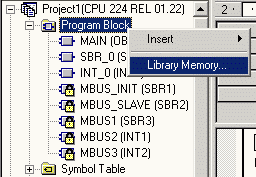
Figure 2
Set the Library Memory in the pop-up tab, as shown in Figure 2: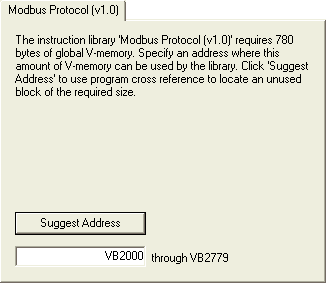
Figure 3. By default, it starts from VB0, but due to conflicts with the Modbus hold register area, it is manually changed to VB2000. Pressing the "Suggest Address" button can also automatically allocate it.
You can use the Suggest Address to set the data area, but be aware that the data area address set by the programming software only considers general addressing and does not take into account settings such as the Modbus data hold register area. It is important to ensure that it does not overlap or conflict with any other used data areas. Do not repeatedly press the Suggest Address button, as this can also cause confusion.
In STEP 7-Micro/WIN32 V3.1, there are different methods for allocating library instruction data areas, and it is necessary to set a starting address in the Symbol Table. We strongly recommend using the latest programming version at the time.
3.2 Add Instruction Libraries
Note:To add a custom instruction library, you need to close the project where the library instructions are edited and create a new project. If you want to add library instructions from other sources, there is no need to do so.
Step 1:Select the Add/Remove Libraries... command in the Micro/WIN File menu; or right-click on the Libraries branch of the instruction tree and select Add/Remove Libraries...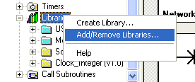
Figure 4. Select Add/Remove Libraries Command
The Add/Remove dialog box will display the user-defined instruction libraries that have been integrated into Micro/WIN on this computer.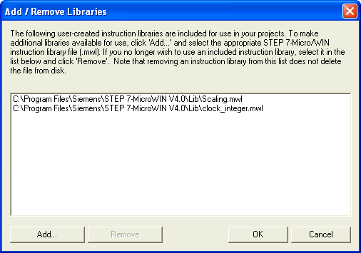
Figure 5. Installed Library Instructions
Step 2:Press the Add button and select the path of the newly defined library file. The user-defined library will be automatically added to the Libraries branch of the Micro/WIN instruction tree.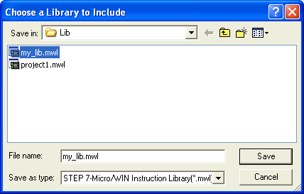
Figure 6. Select Library File
By default, Micro/WIN searches for the library instruction files under the path shown in Figure 8. Users can also specify other paths. However, it is important to keep the library files on non-removable media. If a removable hard drive is specified, an error will occur when the drive is not present, indicating that the library cannot be found. It is recommended that users use the default settings.
3.3 Deleting Library Instructions
Step 1:Select the Add/Delete Instruction Library command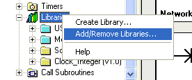
Figure 7. Selecting Commands
Step 2:Select the library file corresponding to the library that needs to be uninstalled, and press the Remove button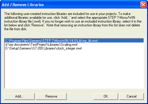
Figure 8. Selecting the Library Instruction File to be Deleted
4RS-485 Network
The PPI, MPI, and PROFIBUS-DP protocols supported by the S7-200 system are typically based on the RS-485 electrical network as the hardware foundation.
The RS-485 serial communication standard employs balanced signal transmission, also known as differential mode. Balanced transmission effectively suppresses interference during transmission.
Balanced transmission uses a pair of wires, utilizing the voltage difference between the two wires to transmit signals. These two wires are designated as A (TxD/RxD-) and B (TxD/RxD+). When the voltage of B is higher than that of A, it is considered to be transmitting a logic "high" level signal; when the voltage of B is lower than that of A, it is considered to be transmitting a logic "low" level signal. The effective differential voltage range is very wide, ranging from a few tenths of a volt to nearly ten volts.
The RS-485 communication port can achieve high communication rates, long communication distances, and parallel connection of multiple ports.
The effective operation of balanced communication is affected by the common-mode voltage difference. The voltage difference between the two wires of the RS-485 interface relative to the signal ground of the communication object is the common-mode voltage. The non-electrically isolated RS-485 interface can resist the interference of common-mode voltage on communication within a certain range.
The common-mode rejection voltage of the S7-200 CPU communication port is 12V. Therefore, for such non-isolated RS-485 ports, it is very important to ensure equipotential signal grounds between communication ports, and it is best to connect them together (not necessarily to ground).
The RS-485 port in the S7-200 system is half-duplex and cannot transmit and receive signals simultaneously.
In the S7-200 system, by selecting appropriate communication devices, a communication network with baud rates ranging from 1200 to 12M, a single segment distance of 1000m, and 32 stations in a single segment can be achieved. Through repeaters, the RS-485 electrical network can also extend the communication distance and increase the number of communication stations. For details, please refer to the dedicated chapter on communication in the "S7-200 System Manual".
Although common RS-485 communication devices are basically consistent in electrical performance, their physical interfaces are diverse and lack unified specifications.
The pin definitions of the D-Sub 9-pin RS-485 port in the Siemens system are basically consistent.
4.1 RS-485 Communication in the S7-200 System
In the S7-200 system, the communication port (programming port) on the CPU and the communication port on the EM277 module both comply with the RS-485 electrical standard.
- The communication port on the S7-200 CPU is non-isolated, with a maximum communication rate of 187.5K baud
- The communication port on EM277 is isolated, with a maximum communication rate of 12M and rate self-adaptation
The following three protocols can all achieve communication based on RS-485 hardware:
- PPI (including communication between programming, S7-200 CPUs, and communication between S7-200 CPUs and HMI, etc.)
- MPI (communication between S7-200 CPUs and S7-300/400 CPUs, between S7-200 CPUs and HMI, between EM277 and HMI, etc.)
- PROFIBUS-DP (communication between EM277 and other PROFIBUS-DP master stations)
 In fact, if the addresses of each communication station are different and the communication baud rates are the same, the above three protocols can simultaneously implement their respective communications on a single RS-485 network. Of course, the protocols supported by a station are limited by its own conditions.
Therefore, when examining the communication of the above electrical networks, we should note that they are all constrained by the electrical fundamentals of the RS-485 network. The network hardware used in the above networks is basically the same.
5. Hardware composition of RS-485 network
In the S7-200 system, whether it is to form a PPI, MPI, or PROFIBUS-DP network, or a Modbus RTU network, the main components used are the same:
- PROFIBUS cable: There are various cable models, among which the most basic is the PROFIBUS FC (Fast Connect) Standard cable (order number 6XV1 830-0EH10)
- PROFIBUS network connector: There are also various forms of network connectors, such as different outlet angles, etc.
5.1 Connecting network connectors
A. Cable and wire stripper. Using FC technology does not require stripping bare copper wires.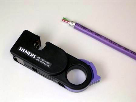
Figure 1. A PROFIBUS cable with one end stripped and a quick stripper (FCS, order number 6GK1905-6AA00).
B. Open the PROFIBUS network connector. First, open the cable tension release block, and then lift the core wire lock.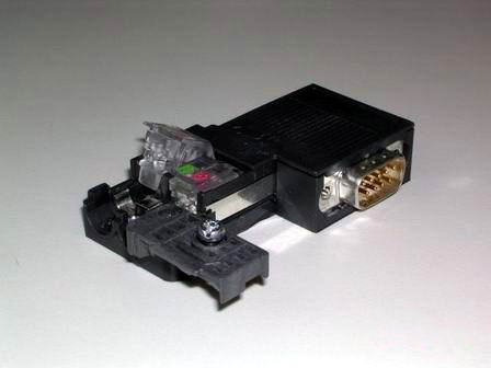
Figure 2. Opened PROFIBUS connector
C. Remove the protective layer from the outside of the PROFIBUS cable core wire, insert the core wire into the core wire lock according to the corresponding color mark, and then press down the lock block firmly to make the internal conductors contact. It should be noted that the stripped shield layer of the cable should be in contact with the shield connection pressure plate.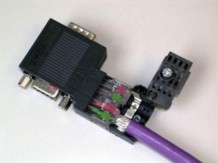
Figure 3. Inserting the cable
Due to the relatively high communication frequency, the communication cable adopts double-ended grounding. Both ends of the cable should be connected to the shield layer.
D. Reset the cable pressure block, tighten the screws, and eliminate the influence of external tension on the internal connection.
5.2 Network connector
Network connectors are mainly divided into two types: those with and without a programming port. Plugs without a programming port are used for general networking, while plugs with a programming port can still provide a programming connection port for programming or connecting to an HMI, etc., while networking.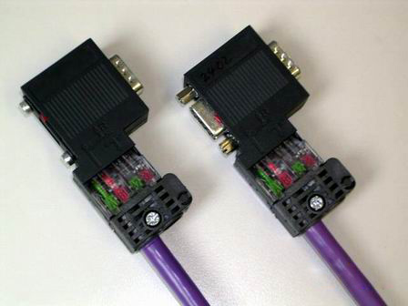
Figure 4. The left side is a network connector without a programming port (order number: 6ES7 972-0BA52-0XA0)
The right side is a network connector with a programming port (order number: 6ES7 972-0BB52-0XA0)
5.3 Linear network structure
Connect network plugs through PROFIBUS cables to form a bus-type network structure.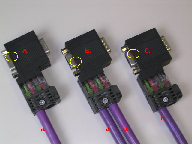
Figure 5. Bus-type Network Connection
In the above figure, network connectors A, B, and C are plugged into the communication ports of three communication stations respectively; cable a connects plugs A and B, and cable b connects plugs B and C. The linear structure can be extended accordingly.
Pay attention to the "terminal resistance" switch setting inside the circle. The terminal resistance switch of the network terminal's plug must be placed in the "ON" position; the terminal resistance switch of the intermediate station's plug should be placed in the "OFF" position.
5.4 Terminal Resistance and Bias Resistance
A formal RS-485 network uses terminal resistance and bias resistance. In cases where the network connection line is very short, temporary, or for laboratory testing, terminal and bias resistors can be omitted.
Terminal Resistance: A resistor connected in parallel on a pair of communication lines at both ends of the linear network (on the two communication ports furthest apart). According to transmission line theory, terminal resistance can absorb reflected waves on the network, effectively enhancing signal strength. The value of the two terminal resistors in parallel should be approximately equal to the characteristic impedance of the transmission line at the communication frequency. Bias Resistance: Bias resistance is used to ensure the relative relationship between A and B signals in complex electrical situations, ensuring the reliability of "0" and "1" signals.
Siemens' PROFIBUS network connectors have built-in terminal and bias resistors, which can be easily turned on or off with a switch. The values of the terminal and bias resistors fully comply with the requirements of Siemens' communication ports and PROFIBUS cables.
Turning on the terminal resistance switch of the network plug in the network can easily cut off the signal transmission of the part of the network behind the plug.
When communicating with other devices (using PROFIBUS cables), the communication port of the other device may not be of the D-SUB9 pin type, or the pin definitions may be completely different. For example, Siemens' MM4x0 frequency converter uses terminal wiring for its RS-485 communication port. In this case, additional terminal resistors need to be connected. Siemens can provide a relatively standardized external resistor. For other devices, technical data from the "S7-200 System Manual" can be referenced for production.
The terminal resistance and bias resistance in Siemens network plugs are matched to the characteristic impedance of Siemens PROFIBUS cables. It is strongly recommended that users use Siemens PROFIBUS cables and network plugs together to avoid many troubles.
Remember the maxim of networking: If you deceive it, it will deceive you!


Leave a Reply