
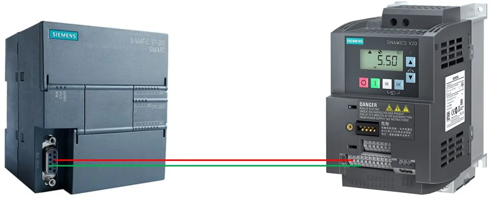
Real-world Cases of MODBUS Communication in Industrial Applications
ModbusIntroduction:
MODBUS communication is widely used in the industrial field, enabling data exchange and monitoring between devices such as PLCs, frequency converters, and instruments.
Example Application:
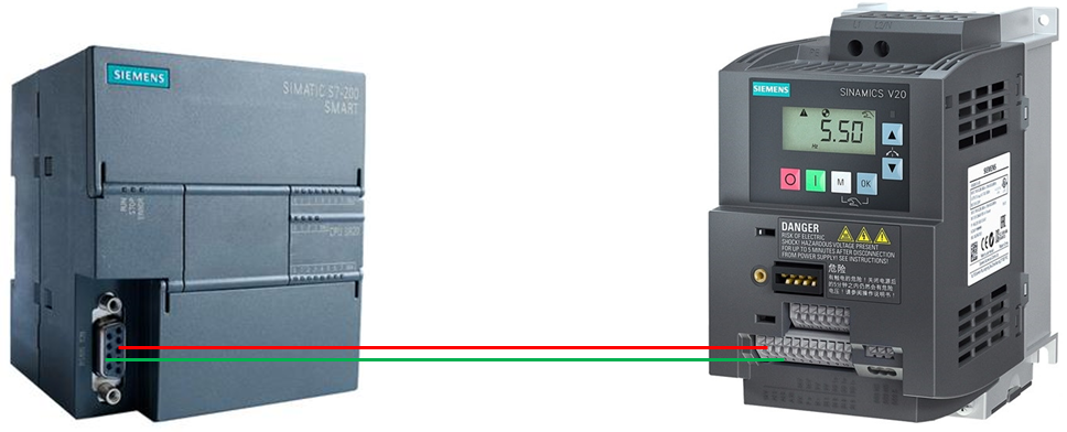
Taking the Siemens 200SMART PLC and Siemens V20 frequency converter as an example, they communicate via MODBUS to achieve forward rotation, reverse rotation, stopping, jogging, as well as reading operational status and voltage/current information.
Implementation Steps:
Hardware Wiring:
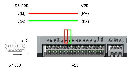
Connect RS485 signals between the Siemens 200SMART and V20 frequency converter (with pin 3 as positive and pin 8 as negative).
Follow the port connection rules (P+ of V20 connects to pin 3, and N- connects to pin 8).
Set Frequency Converter Parameters:
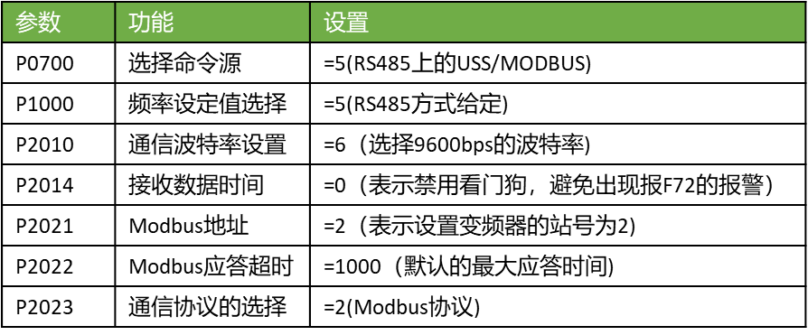
Refer to the V20 frequency converter manual to set MODBUS communication parameters.
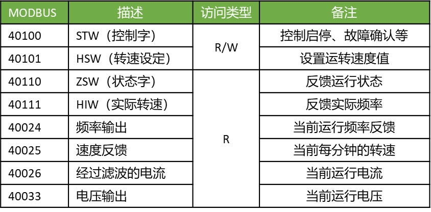
Configure parameters such as speed setpoint (HSW), actual speed (HIW), control word (STW), and status word (ZSW).
Connect to the macro CN011 (ensure it is in the motor data display state).
Communication parameter address:
Identify the registers supported by the V20 frequency converter for control data (such as speed setpoint, actual speed, control word, status word).
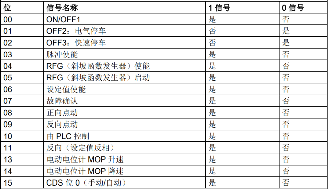
Control word bit definition:
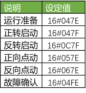
Understand the meaning of each bit of the control word to meet specific control requirements (such as forward rotation, reverse rotation, stop).
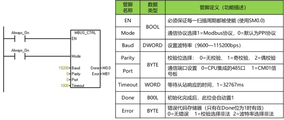
Communication instructions:
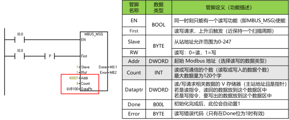
Use two key communication instructions: initialization instruction and data read-write instruction.
To achieve the control requirements of this example, the following two communication instructions must be used: one is the communication initialization instruction, and the other is the communication data read-write instruction. The specific instructions are described as follows:
Programming:
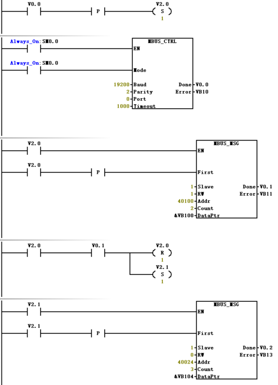
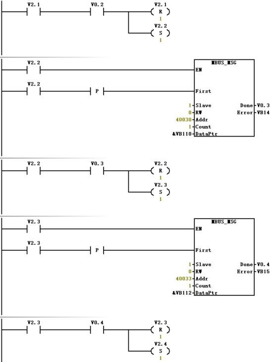
Develop a program that meets specific control requirements (such as forward rotation, reverse rotation, stop, jog).
Integrate communication instructions to achieve data exchange.
Note:The following program is incomplete
Experience summary:
Connection macro selection:
Before selecting a connection macro for the Siemens V20 frequency converter, ensure to first restore the parameters to their default values and perform a quick commissioning.
After selecting the appropriate connection macro, make individual modifications to the parameters.
Hardware wiring tips:
Follow the wiring instructions in the manual, especially for the main circuit wiring.
Ensure accurate wiring of the main circuit section.
Troubleshooting communication issues:
If communication issues persist after parameter setting and program development, consider:
Verify the wiring according to the manual.
Check whether the parameter settings are correct.
Ensure the program executes correctly.
Modification of parameters after selecting a macro:
After selecting the appropriate macro, specific parameters can be individually modified.
Modify the selected parameters as needed.
Important note:
This practical case details the steps for implementing MODBUS communication between Siemens 200SMART PLC and Siemens V20 frequency converter to achieve specific control and monitoring functions.


谢谢分享