
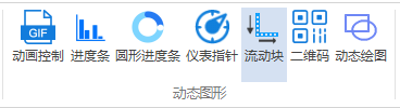
The flow block is used tosimulate the flow of fluid (liquid/gas) in pipelines and ducts: color blocks/images are displaced in designated blocks, visually displaying the working status and motion characteristics of the equipment. It is a "live" element in the images of pumps, fans, and circulation systems.
1. Attribute Introduction
1.1 Function Settings
| Attributes | Description |
|---|---|
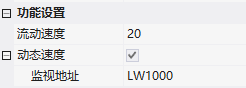
| Flow Speed | Pixels moved per second |
| Dynamic Speed | After checking, the speed is determined by the monitoring address: value 0 indicates no flow; dynamic speed = flow speed × monitoring value |
1.2 Appearance Settings
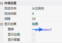
- Flow Direction: From Left to Right/From Right to Left/From Top to Bottom/From Bottom to Top
- Number of Flow Blocks: The number of blocks in the solid color effect;Interval: The proportion of blank space between blocks
- Display Effect: Solid Color (flow block color)/Image (gallery)
- Display Border/Display Background: Border switch and color; Background switch and color (default white) in solid color mode
2. Application Cases
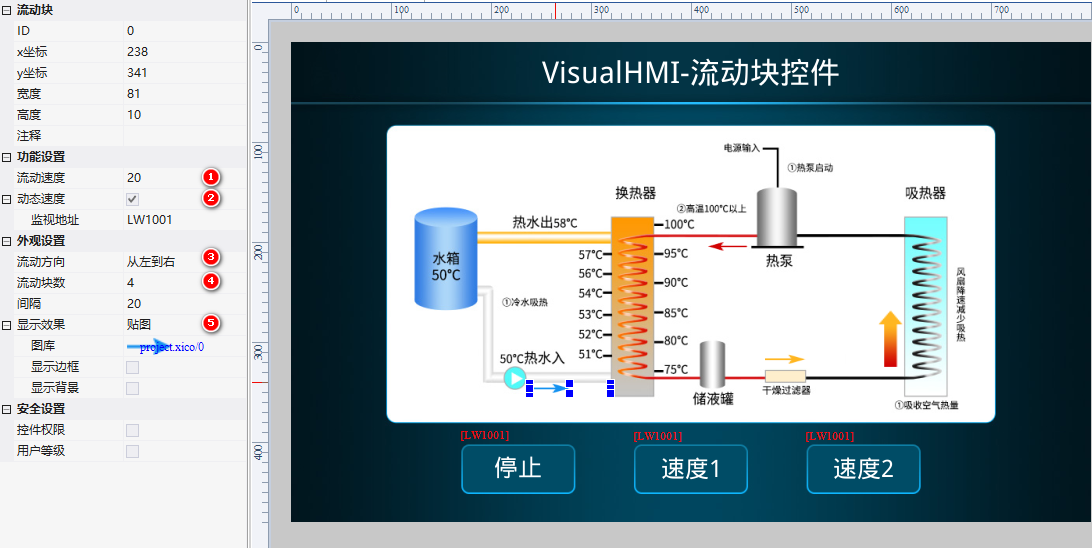
Flow Speed 20, check Dynamic Speed (monitoring)LW1001The direction is from left to right, with 4 blocks and a spacing of 20, achieving a tiled effect. The speed is controlled by the text setting button: LW1001=2 for slow speed, =5 for fast speed, and =0 to stop.
Operation: Change the value of LW1001, and the flow speed changes accordingly. At 0, it is stationary.
Compiled from the VisualHMI development document of Guangzhou Dacai Technology (hmi-doc.gz-dc.com) - configuration control tutorial "Flow Block", copyright belongs to Dacai Technology.


Leave a Reply