
The bit status indicator can only display 0/1, while multi-status indicators are different - they map to multiple predefined states according to the specific valueregister, and each state can be assigned an independent icon, color, and text. Scenarios such as pattern recognition, process stages, and gear display are its strong suits.of the
1. Core capability
- multi-status mapping: Preset multiple status items, each associated with a specific value or value range. For example, 0=stop (gray), 1=automatic operation (green), 2=manual debugging (yellow), 3=fault lockout (red)
- interactive: On registers that allow writing, clicking the control to cycle through states (incrementally 0→1→2→0…)
- non-continuous value mapping: Supports a state transition table, mapping discrete codes such as 0, 5, 10, 99 to states one-to-one, without requiring continuous increment
In industry, status words are often non-continuous codes (compatibility/reserved bits/historical reasons), such as 0=stop, 5=automatic operation, 10=manual mode, 99=serious fault - the state transition table is for this purpose.
2. Attribute introduction
2.1 Function Settings
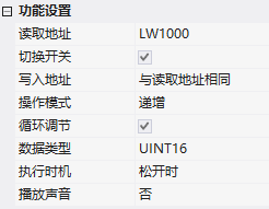
| Attributes | Description |
|---|---|
| Read Address | Register Address for Binding |
| Toggle Switch | Allow Touch Write Operation after Checking |
| Write Address | After Checking the Toggle Switch, you can set whether the write address is the same as the read address |
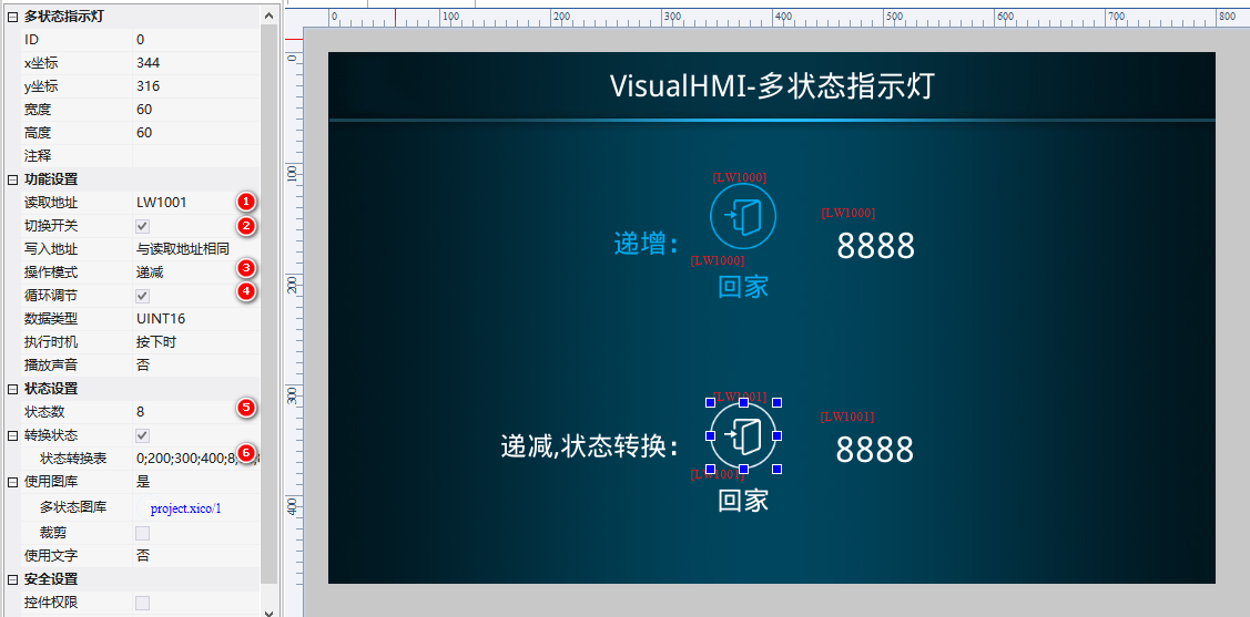
| Operation Mode | Increment: value +1 each time; Decrement: value -1 each time |
| Cyclic Adjustment | If the current state is 7 (the last state) and the state number is 8, click back to 1 |
| Execution timing | Timing for setting registers |
| Data type | UINT16, INT16, UINT32, INT32 |
| Play sound | Play a specified sound when clicked |
2.2 State setting
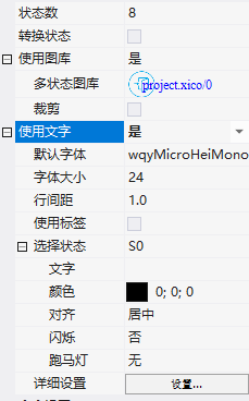
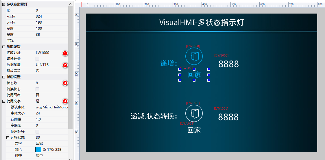
- State number: 1~256 states
- Transition state: Fill in the value mapping according to the state number, such as '0;200;300;400;8;88;888;8888' - register value 0 displays frame 0, 200 displays frame 1, and so on
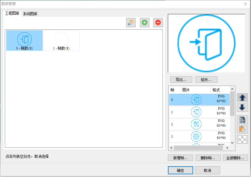
- Use gallery: State 0 gallery/State 1 gallery, cropping;Use text: Different texts for each state, configurable font/size/line spacing/label;Select state: Set the text content, color, alignment, blinking, and marquee for each state individually
3. Application cases
3.1 Incremental mode (cyclic adjustment)
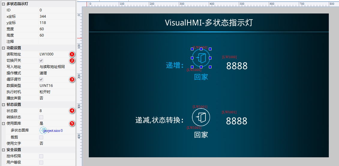
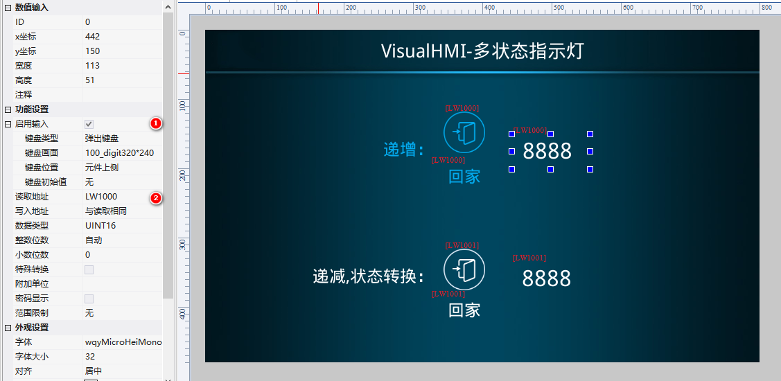
Smart home scenario: 2 multi-state indicator lights (gallery version + text version) + 1 numeric control.LW1000, INT16, with 8 statuses, loop adjustment checked, text statuses S0-Home, S1-Away, S2-Dining...S7-Auto. Click to switch, status and value change in real time.
3.2 Decrease + Status Transition Table
ReadLW1001, with 8 statuses, transition statuses "0;200;300;400;8;88;888" (non-continuous coding), operation mode decreasing. Manually change the value with the numeric control, observe the status follow.
Compiled from Guangzhou Dacai Technology VisualHMI development document (hmi-doc.gz-dc.com) configuration control tutorial "Multi-Status Indicator", copyright owned by Dacai Technology.


Leave a Reply