
The dynamic drawing control allows you tocreate and modify graphical elements(points, lines, circles, rectangles, closed shapes, image cropping) on the HMI, just like a drawing board. Core mechanism: By writing drawing commands through a continuous registersegments - both PLC and LUA can be used for drawing.of
1. Attribute introduction
| Attribute | Description |
|---|---|
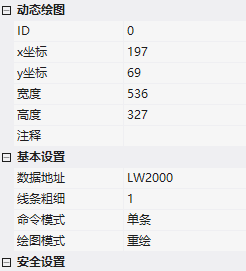
| Data address | Drawing command write address |
| Line thickness | Line segment width in pixels 1~4 |
| Command mode | Single (write one command at a time) / Multiple (write multiple commands at a time) |
| Drawing mode | Redraw (refresh old image with new instructions) / Overlay (continue to add on the screen) |
| Canvas color | RGB color |
| Completion notification | Clear instructions and notify after drawing is completed |
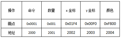
Continuous register format:
LW     CMD         绘制图形类型
LW+1   Draw_Cnt    数据包数量(一个矩形=1个包)
LW+2   DATA        N 个字节数据段
LW+1+N END         结束字段,固定 0xFF00
2. Graphics command list
| Command | Data segment format | Example |
|---|---|---|
| Draw a point (0x0001) | X, Y, Color | AA55 00 0F F1 2000 0001 0001 01F4 00F0 F800 FF00 CCCC (Red point 500,240) |
| Connect endpoints (0x0002) | Number, X, Y of each point (connected as a line), color list | AA55 00 1D F1 2000 0002 0003 FFFF 012C 012C 01F4 012C 01F4 0064 02BC 0064 FF00 CCCC |
| Rectangle (0x0003) | Top left X, Y, bottom right X, Y, color (per rectangle) | AA55 00 1F F1 2000 0003 0002 011E 00AA 01AA 010A 471A 0258 0064 02BC 012C 2C4A FF00 CCCC (Two rectangles) |
| Rectangle fill (0x0004) | Same as above | AA55 00 1F F1 2000 0004 0002 ... FF00 CCCC |
| Circle (0x0005) | Center X, Y, Radius, Color | AA55 00 13 F1 2000 0005 0001 01F4 00FA 0096 FEA0 FF00 CCCC |
| Circle Fill (Command Code Also 0x0005, Source Text Does Not Distinguish Flag Bits) | Ditto | AA55 00 13 F1 2000 0005 0001 0200 0100 0085 FEAA FF00 CCCC |
| Image (0x0007) | PIC ID, Top Left X, Y, Bottom Right X, Y, Target X, Y | AA55 00 19 F1 2000 0007 0001 0000 0021 0027 00A3 0040 0168 0168 FF00 CCCC |
| Closed Area Fill (0x0008) | X, Y, Color | AA 55 00 11 F1 1001 0008 0001 01A4 00F6 F800 FF00 CCCC |
| Spectrum (0x0009) | Quantity, Color, Xn, Yn pairs | AA55 00 33 F1 2000 0009 0005 F800 0168 0064 0064 ... FF00 CCCC (5 vertical lines) |
| Line Segment (0x000A) | Quantity, Color, XnS, YnS, XnE, YnE | AA55 00 33 F1 2000 000A 0004 ... FF00 CCCC |
| Rectangle Inverse Color (0x000D) | Top Left, Bottom Right, Color (Inverse Color = 0xFFFF - Color) | AA55 00 15 F1 2000 000D 0001 0168 00E6 0190 010E 49F1 FF00 CCCC |

PIC ID View: After compilation, there is image.bin in the private resource package; for PIC ID comparison, open build/image.xml under the project directory (id=0 corresponds to the background image of scene 0).
3. LUA drawing (set_array)
In LUA, continuous registers are used to implement drawing. Taking on_update triggering as an example (the word setting button writes values 1~13 of 0xF000 to switch graphics):set_array()Implement drawing by writing to continuous registers. Take triggering with on_update as an example (set the value of the button to 0xF000, and switch between graphics 1-13):
baseGraphCmd = {
  opint=0x0001, Connection=0x0002, rect=0x0003, rectFill=0x0004,
  circle=0x0005, PIC=0x0006, ICON=0x0007, fill=0x0008,
  Spectrum=0x0009, line=0x000A, rectFillOr=0x000D }
-- 画点: 命令, 点数, X, Y, 颜色, 结束
local data = {baseGraphCmd.opint, 0x0003,
  0x01F4, 0x00F0, 0xF800, 0x01F5, 0x00F1, 0xF800, 0x01F6, 0x00F3, 0xF800,
  0xFF00}
set_array(VT_LW, 0x2000, data)   -- 单条模式地址 0x2000
Multiple mode puts multiple graphic commands into an array in order and writes them at once (address 0x3000); overlay mode appends directly without clearing the screen (address 0x4000).



Compiled from the VisualHMI development documentation of Guangzhou Dacai Technology (hmi-doc.gz-dc.com), the configuration control tutorial "Dynamic Drawing" is owned by Dacai Technology.


Leave a Reply