
Go through this entire process: from creating a new project to virtual screen preview, and then to download. Follow along and you will have a solid understanding of the entire development process of VisualHMI. Take the communication between HMI80480M070, Modbus RTU, and PLC as an example.
1. Create a project
Menu [Project] → [New] (or Ctrl+N). Select the project storage path;Select the corresponding resolution and size according to the physical screen- If the physical screen is HMI80480M070, select 800×480 7-inch.
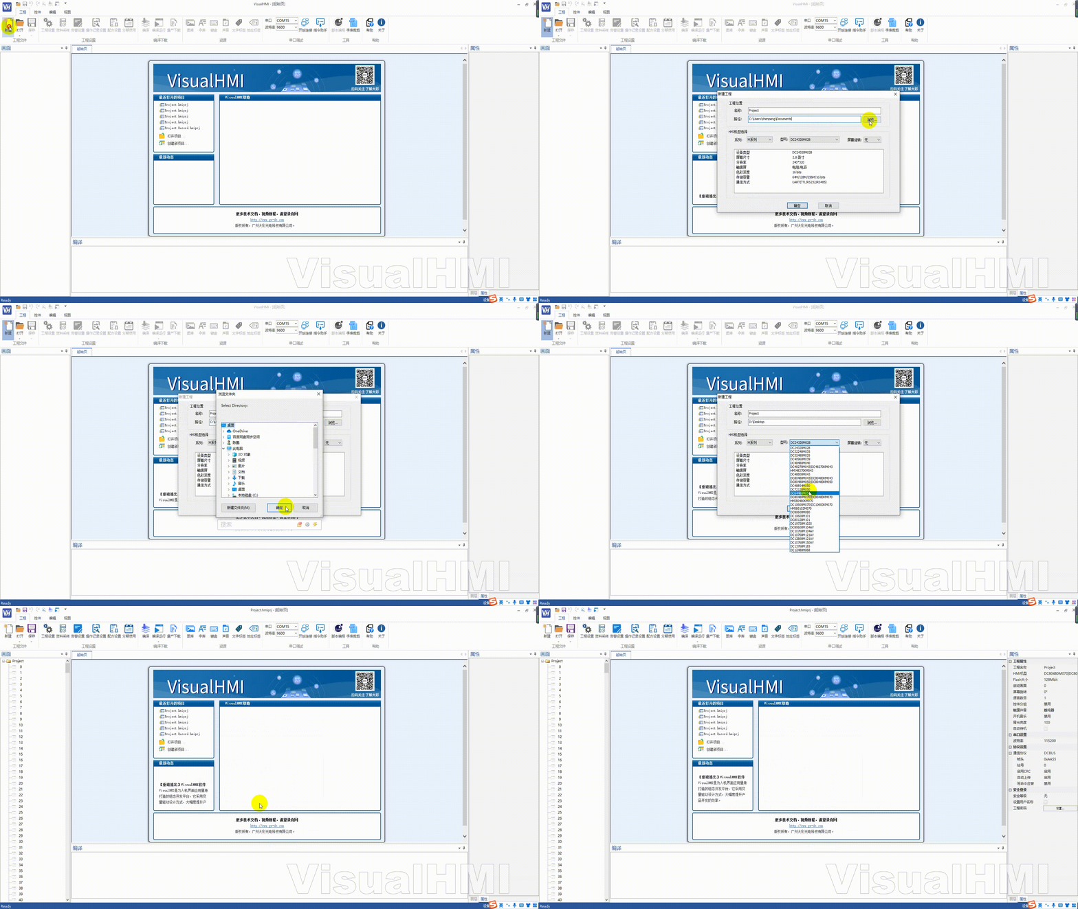
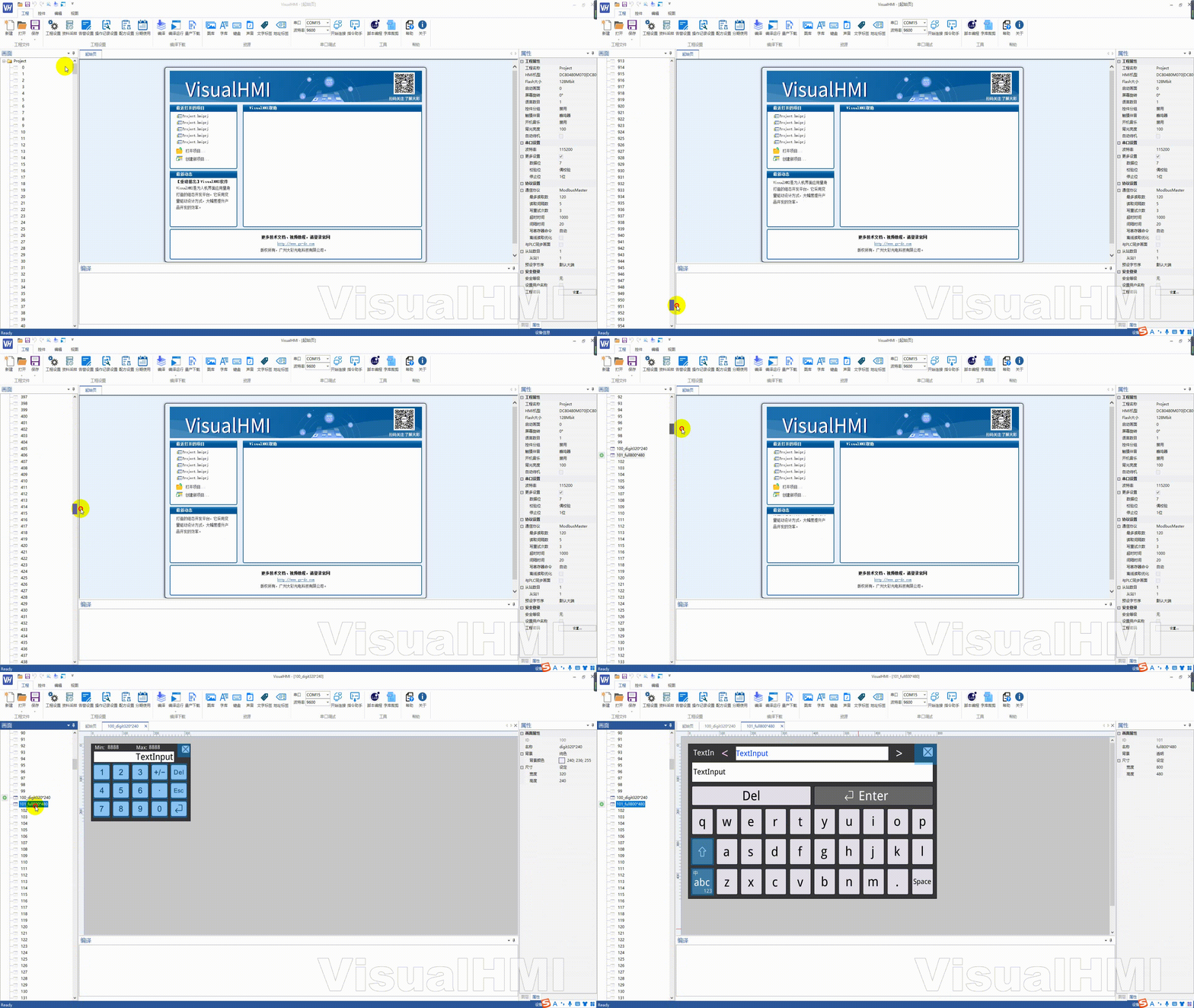
VisualHMI supports up to 999 screens. By default, a new project comes with two keyboard screens: full keyboard screen 101 (800×480) and small keyboard screen 100 (320×240).
2. Protocol Configuration
【 Project 】 → 【 Project Properties 】, configure the serial port and protocol on the right side. The default is the DCBUS protocol. Assuming the PLC serial port is115200 baud rate, 7 data bits, even parity, 1 stop bit, Modbus-RTU, and the screen is in host mode, configure as shown below.
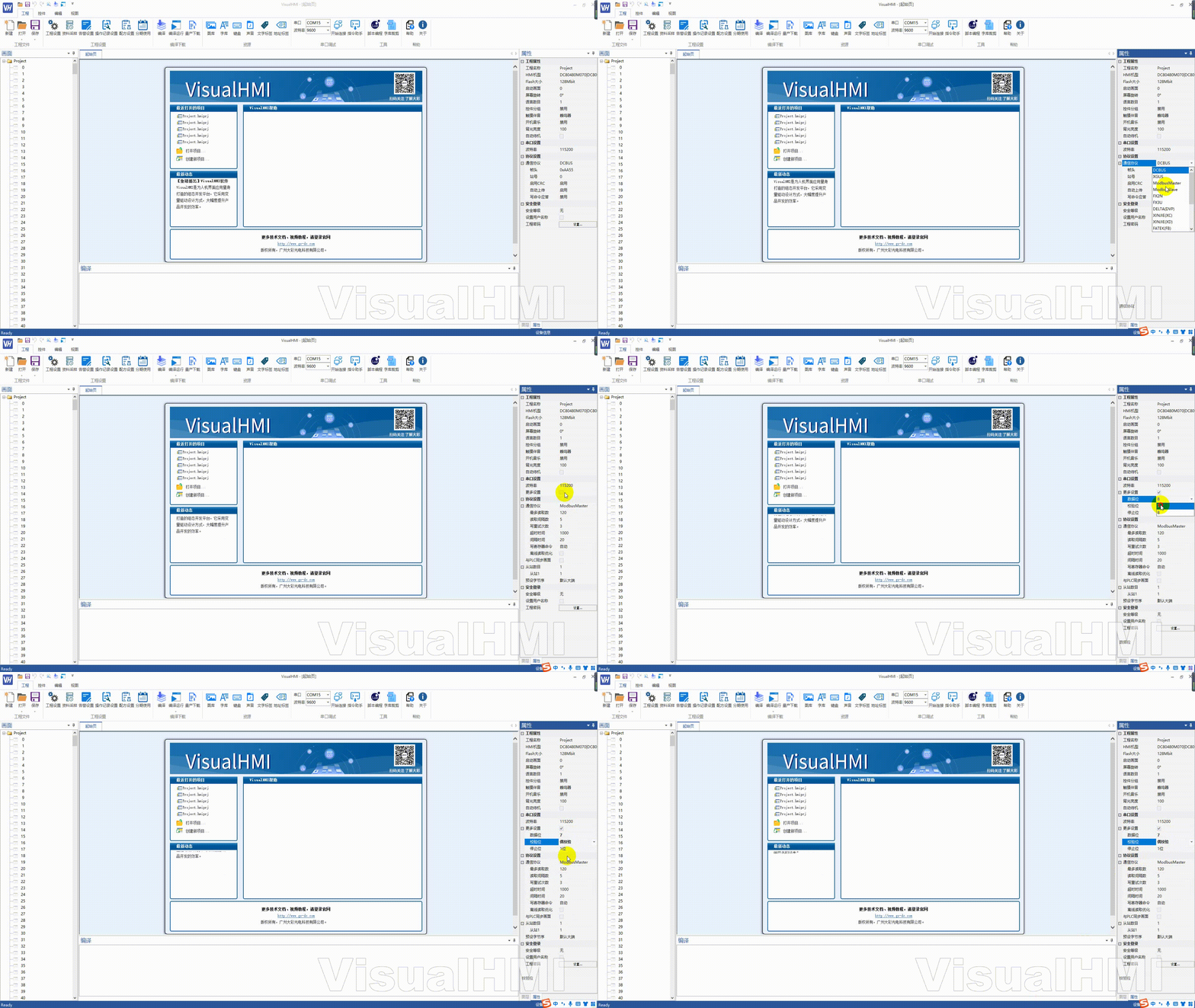
Note: If using Modbus, make sure the PLC side serial port parameters are exactly the same as those of the screen; if using DCBUS/XGUS, only no parity + 1 stop bit is supported.
3. Create a new screen
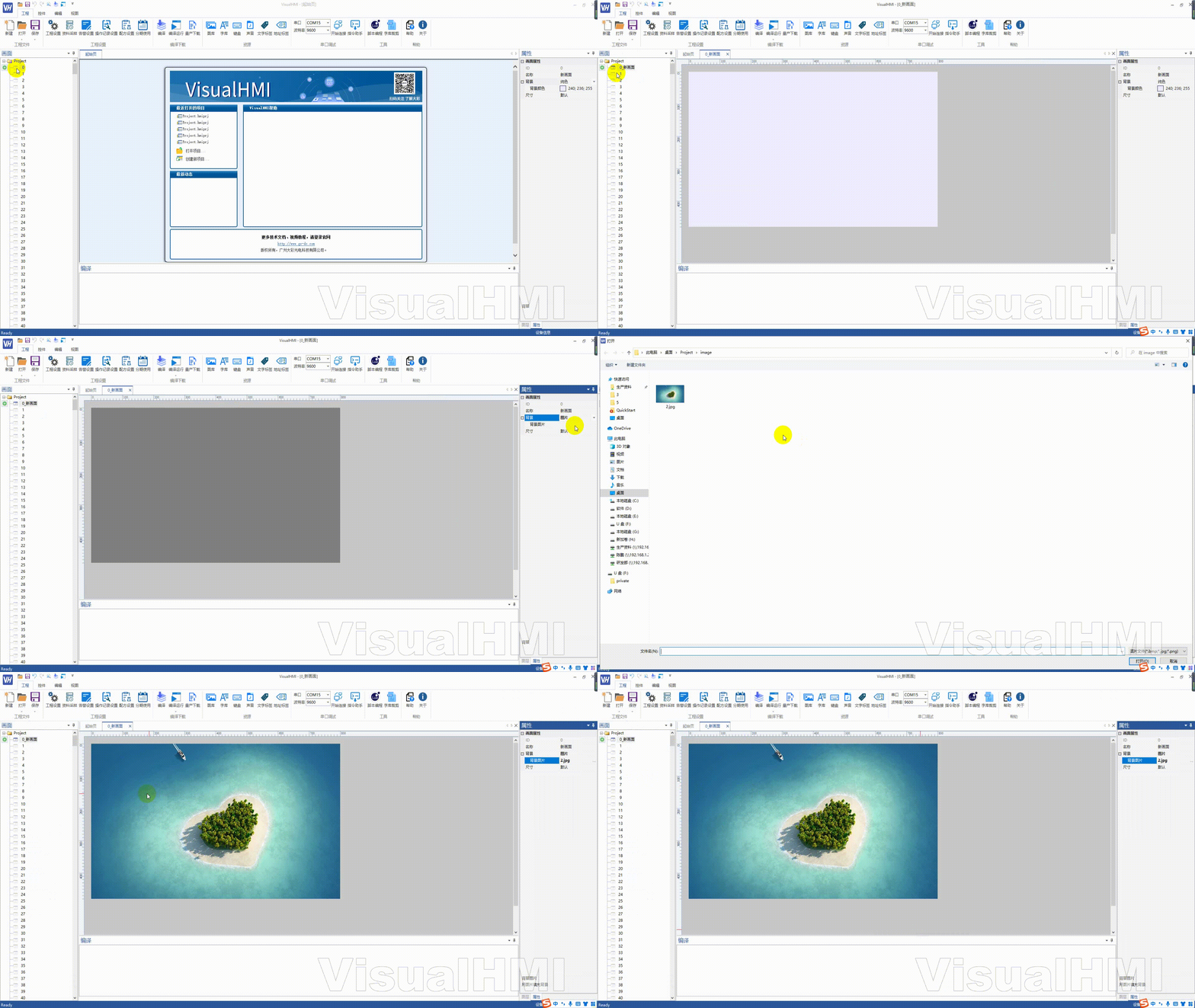
Right-click on the screen ID in the screen area → New, and a solid-color screen will be generated by default. In the [Screen Properties] on the right, the background can be configured as: solid color, image, transparent, or screen. If you choose an image, select a background image.
4. Layout Controls (Bind to PLC Registers)
Taking the display of the value of Modbus hold register 0x0000 as an example:
- Add a [Numerical] control to the screen
- In the control property bar, click "Read Address" - you can manually enter
4x0000or select an address label - . Select PLC Device for Location; select 4x (hold register) for Data Type; fill in 0000 for Hex Address
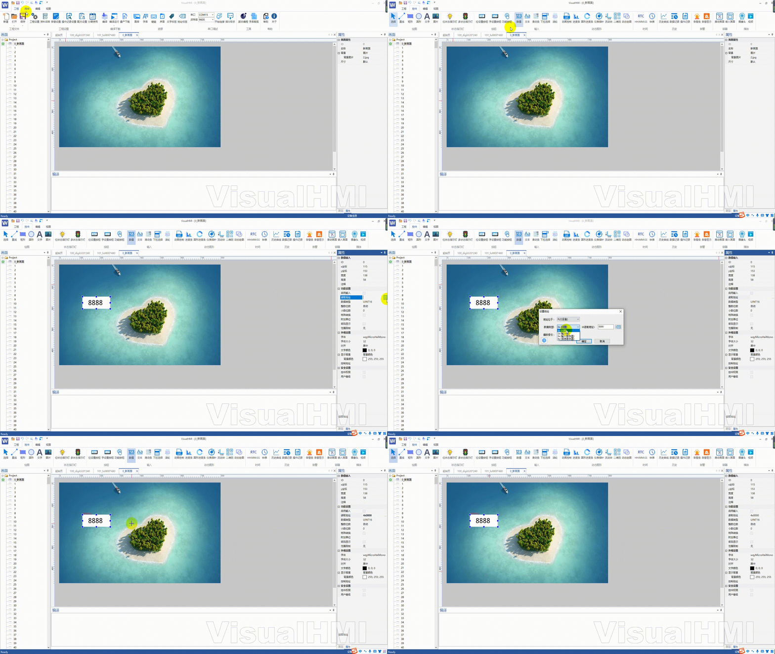
. In this way, the control is bound to PLC hold register 4x0000, and the screen will automatically poll, read, and display.
5. Virtual Screen Preview
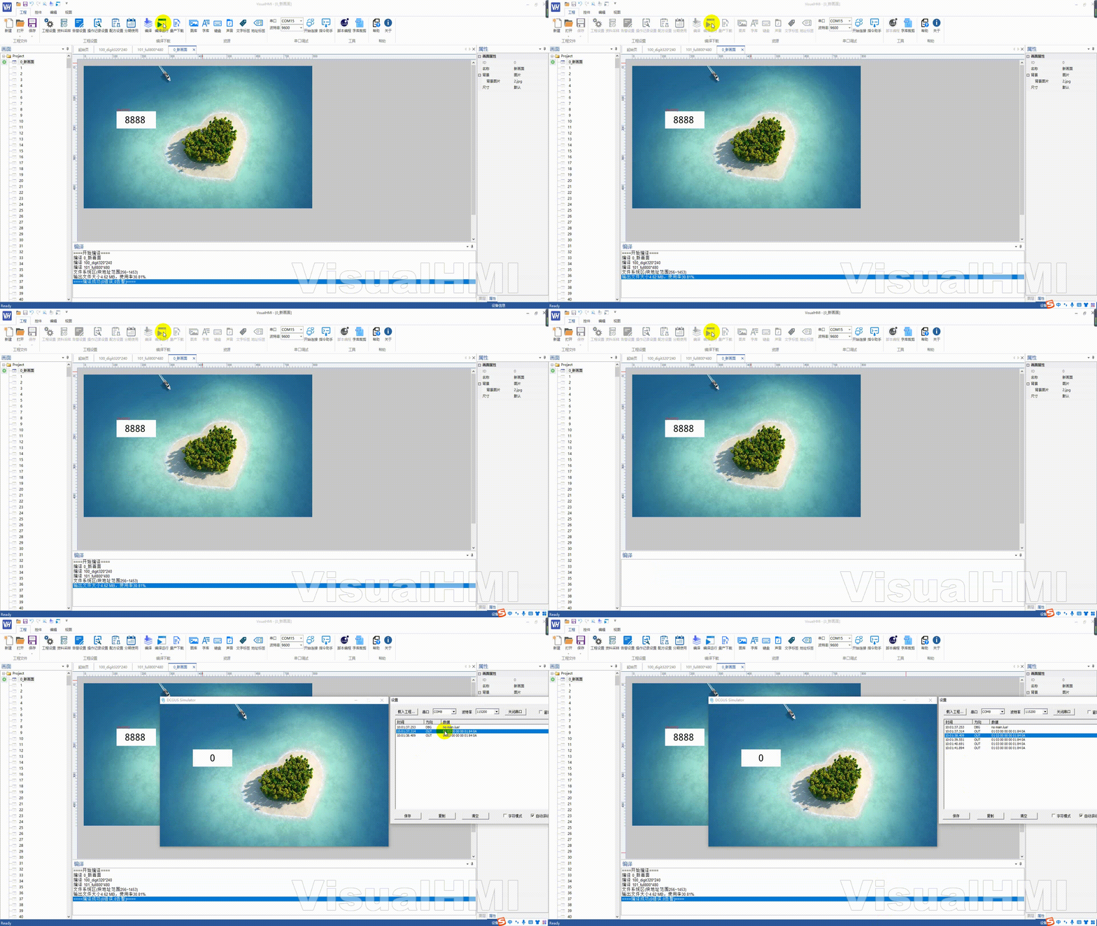
Click on "Project" and then "Run" (Compile and Run). VisualHMI will first compile and then pop up a virtual screen. The command window of the virtual screen will display the issued commands in real-time - for example, accessing the read frame of the 4x0000 register to directly verify if the protocol is correct.
6. Download to the physical screen
First, compile and pass it, then click "Project" → "Mass Production Wizard":Serial port download(Online conditions: screen serial port 8N1, RS485 recommended 19200 / RS232 recommended 115200) orSD card download(generate resource package and copy to the root directory of the SD card).
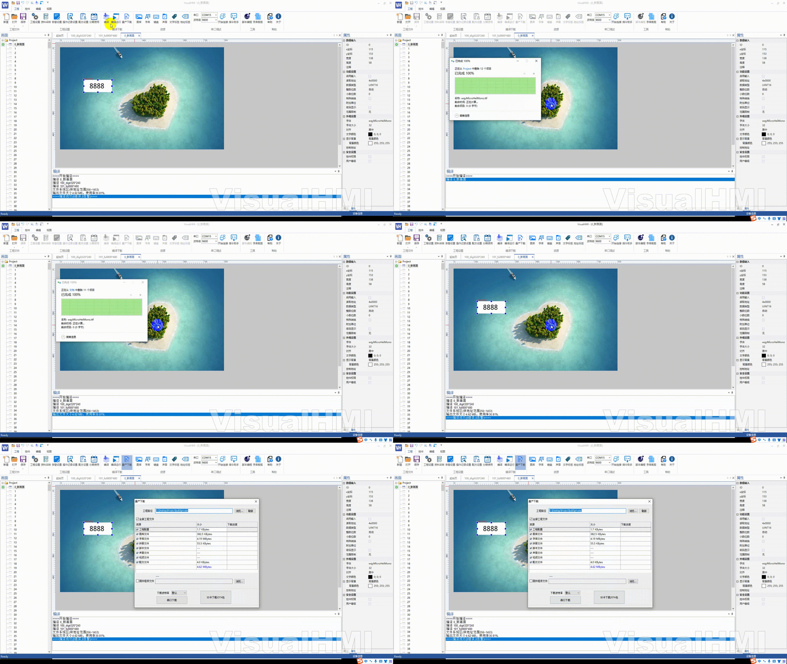
Detailed steps for the two download methods are provided in the "SD Card Download Project" and "Serial Port Download Project" articles respectively.
Compiled from the "VisualHMI" development documentation of Guangzhou Dacai Technology (hmi-doc.gz-dc.com), "Quick Start: Creating a Project", copyright reserved by Dacai Technology.


Leave a Reply