
1.7 Icon Controls and Animation Controls
This section primarily introduces the common applications of icon controls and animation controls in the Modbus protocol. Simple controls can be bound to variables, which can be associated on the configuration page or bound to variables in [Tools - Protocol and Variables - Logic Processing]
In this section, the screen acts as the master station, reading and writing slave commands. If the screen acts as a slave, the application of icon controls and animation controls is the same, and reference can be made. This section uses one set of discrete input variables and two input registers to illustrate the application of icon controls and animation controls, as shown below
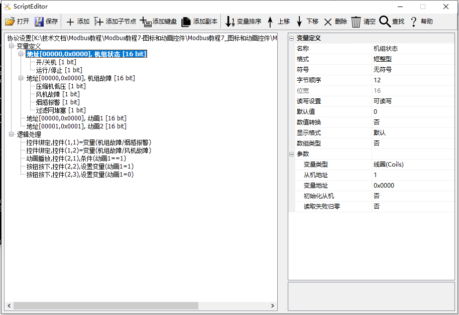
Example routine download link:"Modbus Tutorial 7 - Icon and Animation Controls V1.0"
For protocol activation and variable-related instructions, refer to the link: "Modbus Basic Parameter Description"
1.7.1 Icon Controls
The [Icon Control] screen primarily provides demonstrations on the usage of icon controls. Icon controls are animated files in GIF or ICON format, with the default icon index starting from 0. In the MODBUS protocol, icon controls can be used to bind variables, visually displaying the status of devices
Screen/Logic Configuration
Method 1: Logic Processing Binding
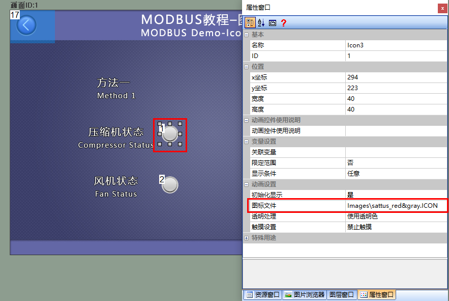
Add an icon control (control ID: 1) to the screen as a display for the slave's "unit fault/compressor status", as shown below
The configuration for control ID: 2 is similar
For the generation of icon files, refer to the link: "ICON Control Application" (click to jump)
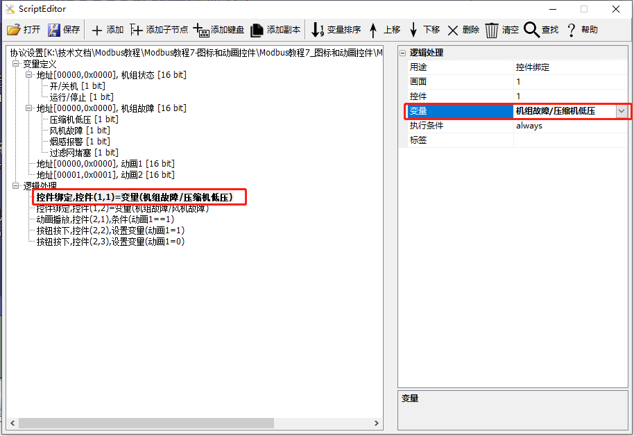
Add a logic processing in the "Protocol and Variable Settings" with the purpose of "Control Binding" and the screen as "1"; the control as "1"; the variable as "Unit Fault/Compressor Low Pressure", as shown below
Method 2: Configure Screen Binding
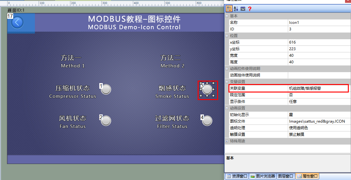
Add an icon control (Control ID: 3) in the screen to display the smoke alarm status of the slave machine. And bind the "Unit Fault/Smoke Alarm" variable in its property bar window. The detailed configuration is as follows
Control ID: 4 follows the same configuration
Run Preview
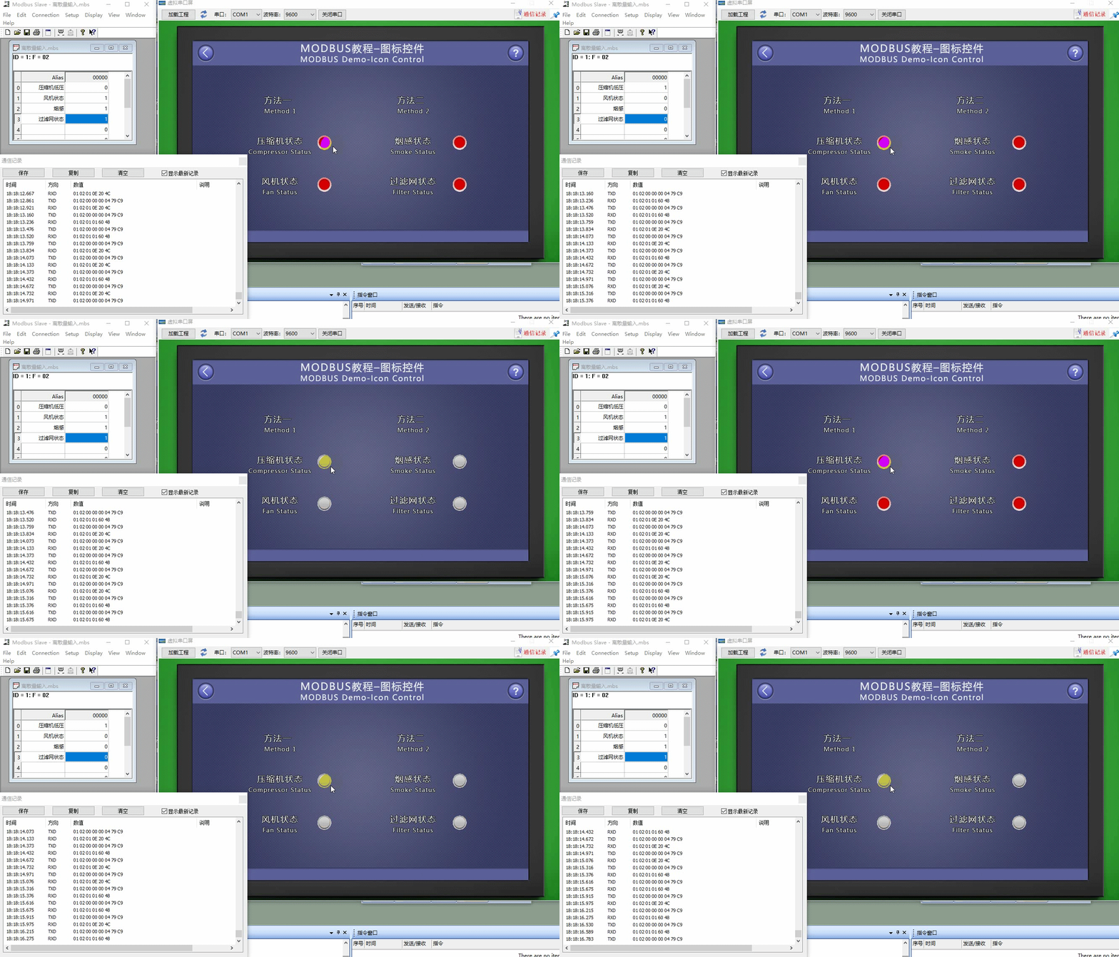
At this time, compile the project and run the virtual serial port screen, connecting with the Modbus Slave software. When the value of the "Unit Fault" variable changes continuously for each node, the display status of the icon control (Control ID: 1~ID4) will be updated accordingly
1.7.2 Animation Control
The "Animation Control" screen mainly provides an example of the use of animation controls. Animation controls are used to play set GIF or ICON format animation files, and can be controlled to pause or play
Screen/Logic Configuration
Method 1: Logical Processing Binding
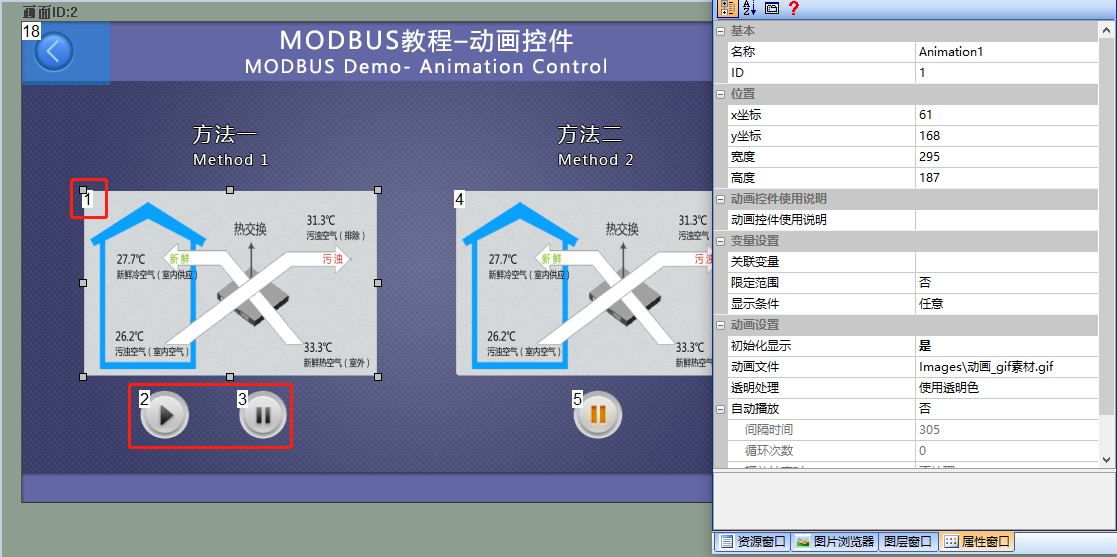
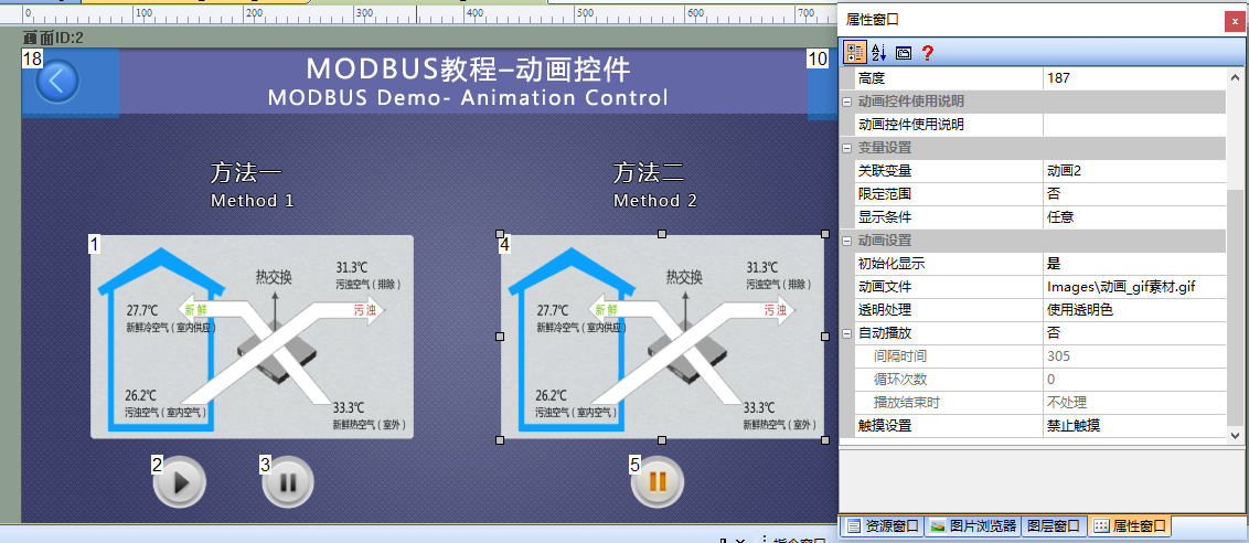
Add an animation control (Control ID: 1) to the screen as a display control for the "animation1" variable of the slave device; simultaneously, add two button controls (IDs 2 and 3) as controls for the playback and pause of the animation control (Control ID1), as shown below
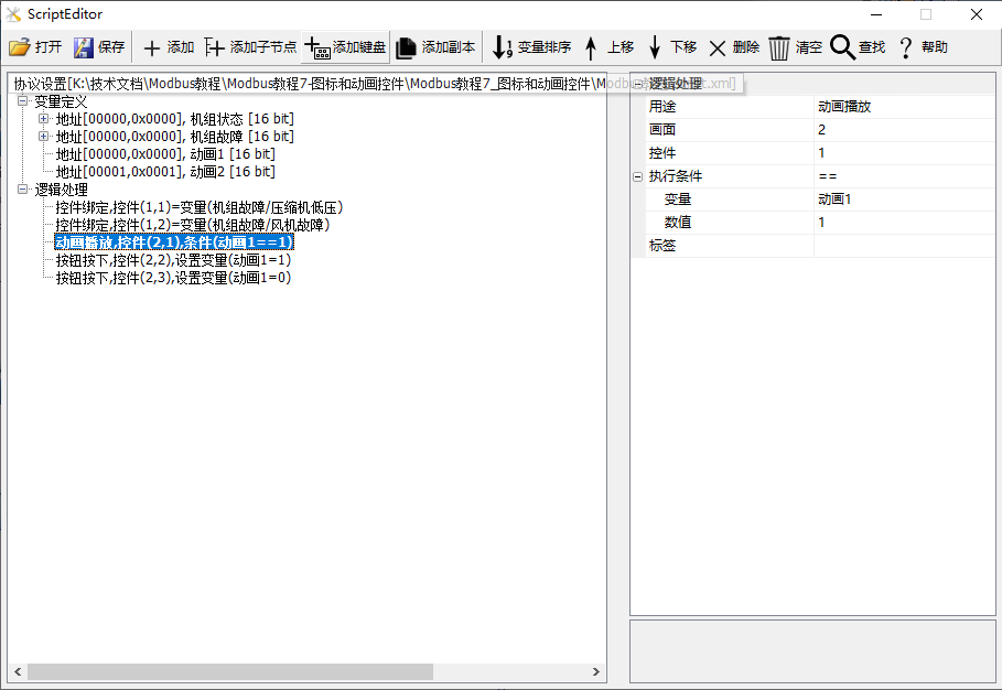
Add 3 logic processes in [Protocol and Variable Settings]:
The first process: Purpose is "animation playback", screen is "2"; control is "1"; and associated with "animation1"
The second process: Controls the playback of the "animation". Purpose is "button pressed", fill in the screen ID as 2 and control ID as 2; execution action is "set variable", variable is "animation1", and set value is 1
The third process: Controls the pause of the "animation". Purpose is "button pressed", fill in the screen ID as 2 and control ID as 3; execution action is "set variable", variable is "animation1", and set value is 0
Method 2: Configuration Screen Binding
Add an animation control (Control ID: 4) to the screen as a display control for the "animation2" variable of the slave device. Bind the "animation2" variable in its property bar window. Add a button control (ID: 5) as a control for the playback and pause of the animation control (Control ID4), as shown below
Run Preview
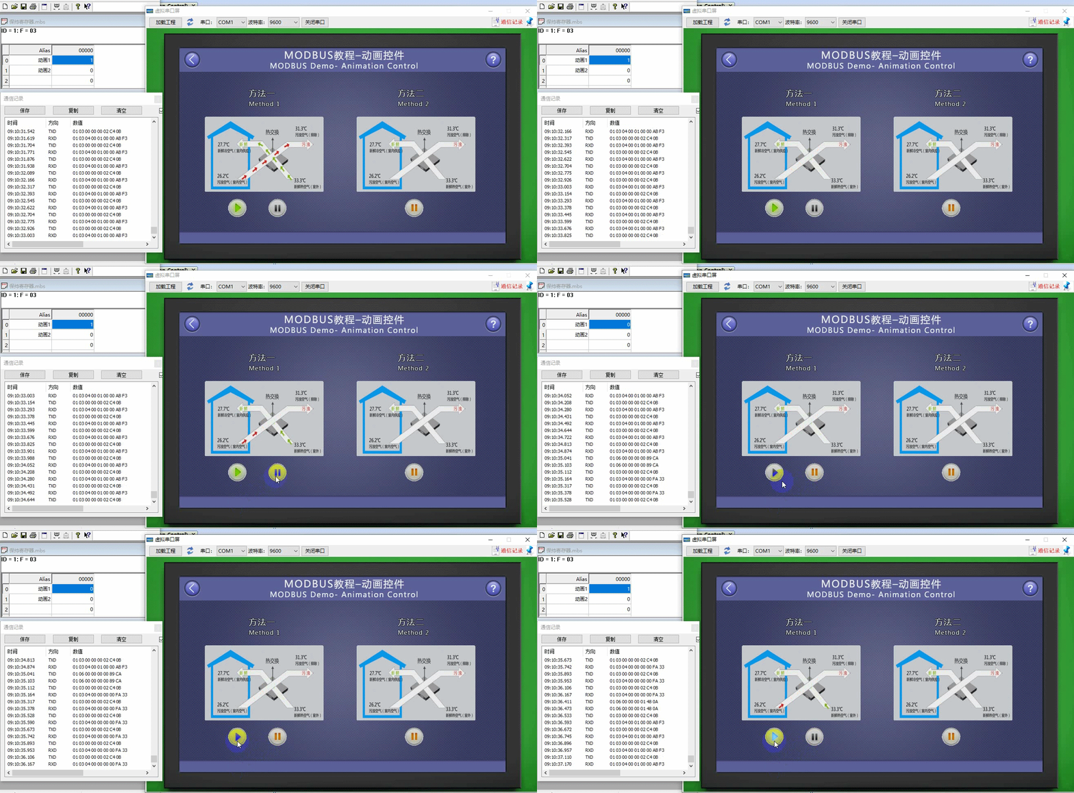
At this point, compile the project and run the virtual serial port screen, connecting it to the Modbus Slave software. When the value of the "animation1" variable is not "0", the animation control (Control ID: 1) plays the animation; meanwhile, clicking the button control (Control ID: 2 or 3) can control the animation control to "play" or "stop", and the value of the "animation1" variable changes accordingly. Similarly, the phenomenon and operation of the animation control (Control ID: 4) are similar.


Leave a Reply