
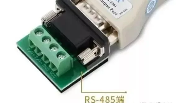
When doing engineering, RS485 control lines are often mentioned. What exactly is it? Today, I will talk about RS485 related applications and gain a deeper understanding of RS485. You will find that there is indeed a lot of knowledge in it. So, let's choose some issues that we usually consider in weak electricity for everyone to understand.
1, What is RS485 bus
Industrial sites often need to collect data from multiple points, analog signals or switch signals, usually using RS485 bus,RS-485 adopts a half duplex working mode and supports multi-point data communication.The RS-485 bus network topology generally adopts a bus type structure with terminal matching. It uses a bus to connect various nodes in series and does not support ring or star networks.
RS485 has no specific physical shape,According to the actual situation of the project, RS485 adopts differential signal negative logic, where+2V to+6V represents "0" and -6V to -2V represents "1".
RS485 has two types of wiring: two-wire and four wire. The four wire system can only achieve point-to-point communication and is rarely used nowadays. The two-wire wiring method is more commonly used, which is a bus topology structure that can connect up to 32 nodes on the same bus.
The communication distance of 485 bus can reach 1200 meters.According to the theory of 485 bus structure, under ideal conditions, the transmission distance of 485 bus can reach 1200 meters. The condition is that the communication cable is of high quality and meets the standard, with a baud rate of 9600, and only one 485 device is loaded to achieve a communication distance of 1200 meters. Therefore, the actual stable communication distance of the 485 bus is often not up to 1200 meters. If there are multiple 485 devices, the impedance of the wires does not meet the standard, the wire diameter is too thin, the quality of the converter is poor, the lightning protection of the equipment is complex, and the baud rate is increased, all factors will reduce the communication distance.
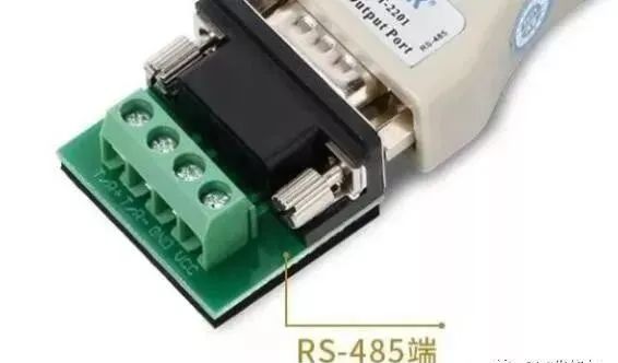
2, RS485 cable
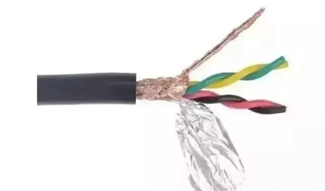
In general, ordinary twisted pair cables can be used, while coaxial cables with shielding layers can be used in high demand environments. When using the RS485 interface, for a specific transmission line, the maximum cable length allowed for data signal transmission from the RS485 interface to the load is inversely proportional to the baud rate of the signal transmission. This length data is mainly affected by signal distortion and noise.
In theory, the maximum transmission distance of RS485 can reach 1200 meters, but in practical applications, the transmission distance is shorter than 1200 meters, and the specific transmission distance depends on the surrounding environment.During the transmission process, the signal can be amplified by adding relays, up to a maximum of eight relays. In theory, the maximum transmission distance of RS485 can reach 9.6 kilometers. If long-distance transmission is really needed, optical fiber can be used as the propagation medium, with an optoelectronic converter added at each transmitting and receiving end. The transmission distance of multimode fiber is 5-10 kilometers, while using single-mode fiber can achieve a propagation distance of 50 kilometers.
3, Precautions for RS485 wiring installation
1. What kind of communication cable should be used for 485 bus? How many devices can be connected to a bus?
RVSP shielded twisted pair cables must be used. The specifications of the shielded twisted pair cable used are related to the distance from the 485 communication line and the number of devices attached, as shown in the table below. The use of shielded twisted pair cables helps to reduce and eliminate distributed capacitance between two 485 communication lines, as well as common mode interference from around the communication lines.
Some people say that the 485 bus can communicate with 128 devices.
In fact, not all 485 converters can carry 128 devices. It is necessary to determine the load capacity based on the model of the chip inside the 485 converter and the model of the 485 device chip. Only chips with lower indicators can be used to determine their load capacity. There are generally three levels of load capacity for 485 chips -32, 128, and 256. In addition, the theoretical nominal value is often unattainable in practice. The longer the communication distance, the higher the baud rate, the thinner the wire diameter, the worse the wire quality, the worse the converter quality, the insufficient power supply of the converter (passive converter), and the stronger the lightning protection, all of which will reduce the actual load capacity.
Most engineering companies are accustomed to using Category 5 or Category 5e network cables as 485 communication lines, which is incorrect. This is because:
Ordinary network cables do not have shielding layers, which cannot prevent common mode interference.
(2) Do not use Ethernet cables with a diameter that is too thin, as it may reduce transmission distance and the number of devices that can be attached. Use at least 0.4mm square or standard Ethernet cables.
(3) Network cables are single stranded copper wires that are more prone to breakage compared to multi-core wires.
2. Why grounding
The 485 transceiver can only operate normally when the specified common mode voltage is between -7V and+12V. If it exceeds this range, it will affect communication and seriously damage the communication interface. Common mode interference will increase the common mode voltage mentioned above. One effective way to eliminate common mode interference is to use the shielding layer of the 485 communication line as a ground wire, connecting equipment in networks such as machinery and computers together, and reliably connecting them to the ground through a single point.
3. How to route 485 communication cables
Communication lines should be kept as far away as possible from interference sources such as high-voltage power lines and fluorescent lamps. When communication lines cannot avoid interference sources such as power lines, they should be perpendicular to the power lines, not parallel, and not tied together. High quality twisted pair cables should be used for wiring.
4. Why does the 485 bus adopt a handle structure instead of a star structure?
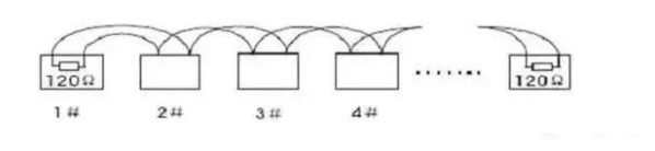
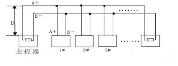
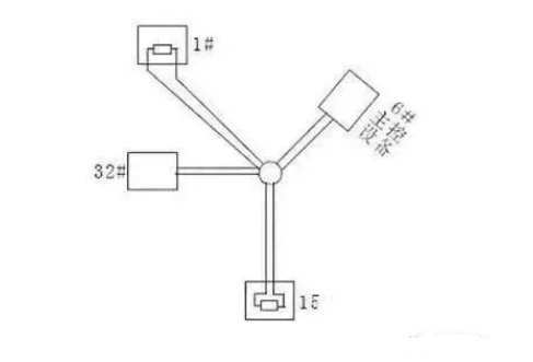
The star shaped structure will generate reflected signals, which will affect 485 communication. The length of the branch line from the bus to each terminal device should be as short as possible, generally not exceeding 5 meters. If the branch line is not connected to the terminal, there will be reflected signals, which will cause strong interference to communication. It should be removed, and it is best to connect a 120 Ω terminal resistor at both ends of the RS485 device.
Handle connection as shown in the figure:
Star shaped connection as shown in the figure:
5. Can there be connections between devices on the 485 bus?
In the same network system, use the same type of cable to minimize the number of connections in the circuit. Ensure good welding and tight wrapping at the joint to avoid looseness and oxidation. Ensure a single, continuous signal channel as the bus.
6. What are common mode interference and differential mode interference? How to eliminate interference on communication lines?
The 485 communication line consists of two twisted pair wires, which transmit signals through the voltage difference between the two communication lines, hence it is called differential voltage transmission. Differential mode interference is transmitted between two signal lines and belongs to symmetric interference. The method to eliminate differential mode interference is to add a bias resistor (matching resistor in the ball machine) to the circuit and use twisted pair cables; Common mode interference is transmitted between signal lines and ground and belongs to asymmetric interference. The methods to eliminate common mode interference include:
(1) Adopt shielded twisted pair cables and effectively ground them.
(2) Galvanized pipes should also be considered for shielding in areas with strong electric fields.
(3) When wiring, stay away from high-voltage lines, and do not bundle high-voltage power lines and signal lines together.
(4) Adopt linear regulated power supply or high-quality switching power supply (ripple interference less than 50mV).
7. Under what circumstances should terminal resistance be increased on the 485 bus?
In general, it is not necessary to increase terminal resistance. Only when the 485 communication distance exceeds 300 meters, terminal resistance should be added at the beginning and end of the 485 communication. Especially when there are fewer devices on the 485 bus. When there are a large number of devices (such as more than 22). Generally, it is not necessary to increase the terminal resistance because it will reduce the load capacity of the 485 bus. The connection method of the 120 Ω matching resistor for the ball machine terminal is as follows: the 120 Ω matching resistor for the ball machine terminal can be connected by dialing the code switch on the ball machine chassis. When the ball machine leaves the factory, the 120 Ω matching resistor defaults to not connected. You can connect the 120 Ω matching resistor to the circuit by turning the 10th position of the dip switch to ON. On the contrary, if a 120 Ω matching resistor is not connected, turn the 10th bit to OFF.
8. Problems in practical applications
In actual construction use, users often use the star connection method, in which case the terminal resistor must be connected to the two devices with the farthest distance from the line (as shown in the figure below, devices 1 # and 15 #). However, because this connection method does not meet the requirements of the RS485 industrial standard, it is easy to cause signal reflection, decreased anti-interference ability, and other problems when the distance between each device's line is far, resulting in a decrease in the reliability of the control signal. At this point, the phenomenon that occurs is that the ball machine is completely uncontrolled or cannot stop running on its own.
For this situation, it is recommended to add an RS485 distributor. This product can effectively convert star connections into connection methods that comply with the RS485 industry standard, thereby avoiding problems and improving communication reliability, as shown in the following figure.

9. Recommended line for maximum transmission distance without relay
(1) Ordinary twisted pair shielded cable STP-120 Ω (for RS485&CAN) one pair 20 AWG, with an outer diameter of about 7.7mm. Suitable for indoor, pipeline, and general industrial environments. When in use, one end of the shielding layer should be grounded!
(2) Ordinary twisted pair shielded cable STP-120 Ω (for RS485&CAN) one pair 18 AWG, with an outer diameter of about 8.2mm. Suitable for indoor, pipeline, and general industrial environments. When in use, one end of the shielding layer should be grounded!
(3) Armored twisted pair shielded cable ASTP-120 Ω (for RS485&CAN) one pair 18 AWG, with an outer diameter of approximately 12.3mm. Can be used in places with severe interference, frequent rodent infestations, and lightning and explosion protection requirements. When in use, it is recommended to ground both ends of the armor layer and the innermost shielding end
4, Common faults and solutions of RS485
1, How to prevent the occurrence of faults?
To reduce communication failures, the following suggestions are proposed.
1. It is recommended that users use and purchase the 485 converter provided by the manufacturer or the 485 converter recommended by the manufacturer.
2. The manufacturer will conduct extensive testing on the 485 converter that comes with it, and will require the 485 converter manufacturer to produce and quality check it according to its fixed performance parameters, so it has good compatibility with access control equipment. Don't be tempted to buy cheap 485 converters from miscellaneous manufacturers.

3. Strictly follow the construction specifications of 485 bus for construction, and eliminate any lucky mentality.
4. Adopt scientific and reserved solutions for 485 bus projects with long lines and heavy loads.
5. If the communication distance is too long, such as over 500 meters, it is recommended to use a repeater or 485HUB to solve the problem.
6. If there are too many loads, such as more than 30 on a bus, it is recommended to use 485HUB to solve the problem.
7. On site debugging with all debugging equipment. During on-site debugging, it is necessary to carry several converters that can connect long distances and multiple loads, a commonly used computer laptop, a multimeter for testing circuit breakers, and several 120 ohm terminal resistors.
2, What are the common communication faults when using the 485 bus structure?
1. Communication is not available and there is no response.
2. You can upload data, but you cannot download data.
3. The system prompts interference during communication, or the communication indicator light keeps flashing when there is no communication.
4. Sometimes communication is possible, sometimes communication is not possible, some commands can work, and some commands cannot work.
3, What are the debugging methods when a malfunction occurs?
Before debugging, it is necessary to ensure that the equipment wiring is correct and the construction complies with the specifications. You can use the following debugging methods based on the problems encountered.
1. Common law:
Connect the GND ground of all 485 devices with one wire or shielded wire to avoid potential differences that may affect communication between all devices.
2. Terminal resistance method:
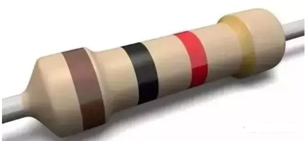
Connect 120 ohm terminal resistors in parallel to 485+and 485- of the last 485 device to improve communication quality.
3. Intermediate segmentation method:
By disconnecting from the middle, check whether the device is overloaded, the communication distance is too long, and whether a certain device has an impact on the entire communication line.
4. Separate line drawing method:
Simply pull a separate line to the device, which can be used to troubleshoot whether the wiring caused the communication failure.
5. Replacing converter method:
Carry a few converters with you to rule out whether the quality of the converters is affecting the communication quality.
6. Notebook debugging method:
First, make sure that the computer or laptop you carry with you is a device with normal communication. Use it to replace the client's computer for communication. If it is normal, it indicates that the client's computer's serial port may be damaged or injured.
Additional on-site experience in 2026: Guidelines for wiring and pit layout of large projects
In nearly a hundred industrial field projects, we have summarized the following high-frequency pitfalls and best practices:
- The separation distance between strong and weak electricity should be at least 30cmWhen the RS485 signal line is parallel to the power cable (380V/220V), the interval should not be less than 30cm, and when crossing, it should be perpendicular. When the distance is not enough, it is necessary to use double shielded cables (aluminum foil+braided mesh double-layer shielding), and the shielding layer should be grounded at one end.
- Hand in hand bus, strictly prohibit star shaped branchesThe reflected signal generated by the star topology will be superimposed on the main line, resulting in packet loss or the entire bus going offline. If a branch structure is indeed needed on site, use485 hub or repeaterIsolate each branch.
- Consistency of power supply for terminal devicesIf devices powered by 12V and 24V are mixed on the bus, it is necessary to ensure that GND is grounded. Common mode voltage exceeding the standard may occur between devices that are not on the same ground, resulting in permanent damage to the transceiver chip.
- Reserved debugging interfaceIt is recommended to reserve a debugging connection port at each end and midpoint of the bus for easy troubleshooting using Modbus debugging tools in the future.
Modbus.cn provides industrial grade RS485 isolation repeaters, hubs, and various gateway devices. Please refer to the product center for detailed parameters.


Leave a Reply