
In RS-485 bus applications, communication between different RS-485 devices often occurs. The compatibility among different devices varies, with some devices being very stable while others frequently receive abnormal data. What causes this? And how can it be avoided?
RS-485 Application Anomalies
A certain energy storage customer frequently experiences data instability when using ZLG's fully isolated RS-485 transceiver chip SM4500, as shown in Figure 1 below. When the customer's device communicates with different RS-485 devices, some devices communicate stably, while others occasionally receive abnormal levels.
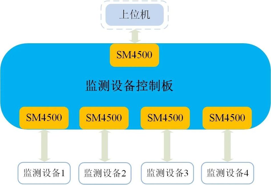
Figure 1 Simplified Diagram of SM4500 Application
Testing revealed that when the RS-485 channel of the customer's board is idle, the bus level is at 0 potential. As shown in Figure 1, the RS-485 standard specifies that when the level between the AB buses is between -200mV and +200mV, the receiver terminal (RXD) will receive an uncertain level (hereinafter collectively referred to as "threshold level" for ease of explanation). Different RS-485 devices have different threshold levels, with the SM4500 threshold level being between -10mV and -200mV. When communicating with devices with threshold levels between -200mV and +200mV, anomalies may occur. So, how can this issue be avoided?
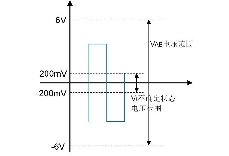
Figure 2 Schematic Diagram of RS-485 Reception Level
Reasons for Bus Level Uncertainty
1. Indispensable Pull-up and Pull-down Resistors
As shown in Figures 3 and 4, which depict the bus waveform during SM4500 communication, when sending data (non-idle state), the maximum bus level is 3.28V and the minimum is -2.96V; in the idle state, the maximum bus level is 240mV and the minimum is -160mV, indicating that the bus is already in an uncertain state.
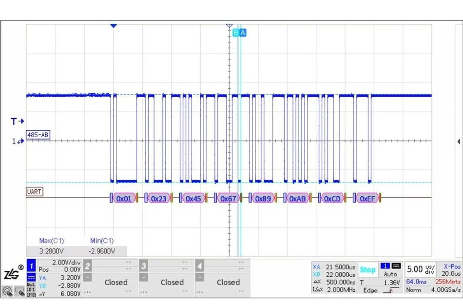
Figure 3: SM4500 2Mbps bus waveform when not idle
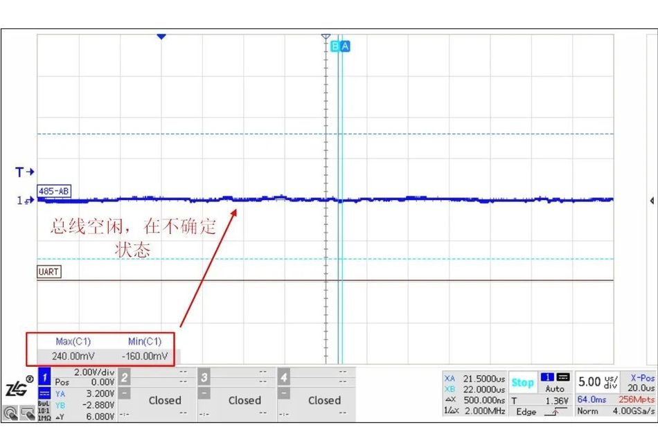
Figure 4: Bus waveform of SM4500 when idle
According to the typical connection circuit diagram in the SM4500 manual, after adding pull-up and pull-down resistors to the bus, the bus level is pulled up, which is now much higher than the indeterminate state voltage, as shown in Figure 6. It can be seen that in RS-485 applications, pull-up and pull-down resistors are essential.
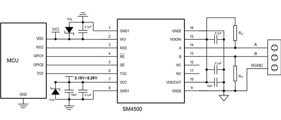
Figure 5: Typical connection circuit diagram of SM4500
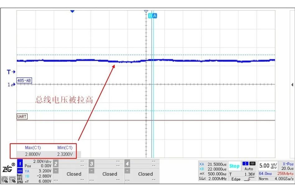
Figure 6: Waveform of SM4500 when idle (with pull-up and pull-down resistors set to 100kΩ)
2. "Redundant" terminal resistors
As engineers are aware, the role of terminal resistors is to eliminate signal reflection, so they are often set by default in practical applications. However, not all situations require terminal resistors, and sometimes they can even introduce problems. As mentioned earlier, when the bus is idle and in an uncertain state, it can be avoided by setting pull-up and pull-down resistors. However, after connecting terminal resistors, the bus level will enter an uncertain state again, as shown in Figure 7. How can this be resolved?
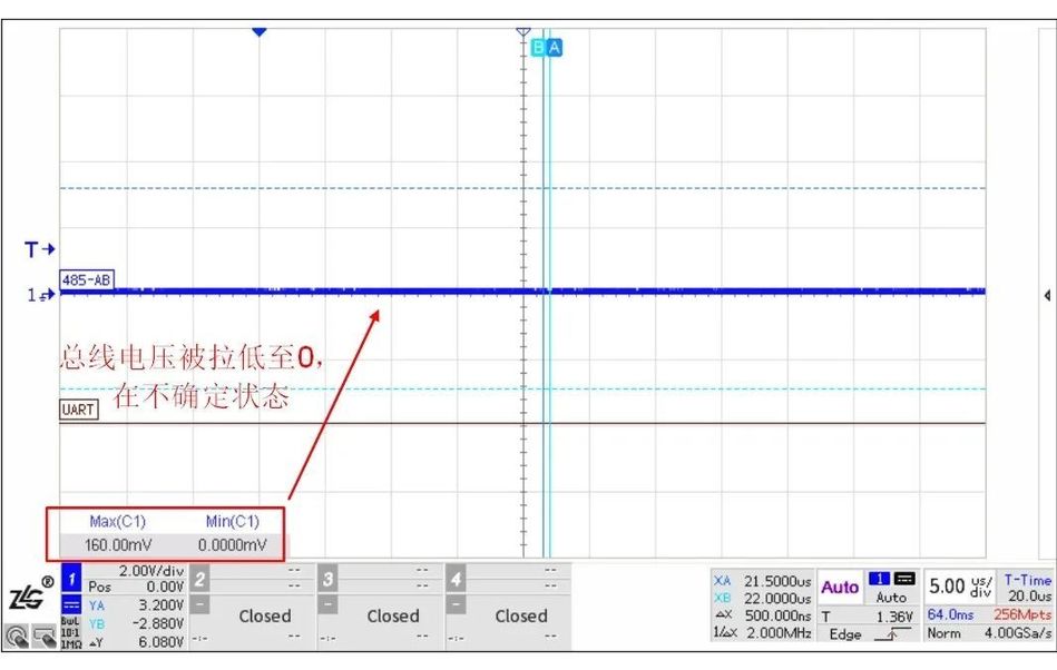
Figure 7: Waveform of SM4500 when idle (with pull-up and pull-down resistors set to 100kΩ and a 60Ω terminal resistor)
How to keep the bus from being within the threshold level
Let's first look at why the bus level will enter an uncertain state again after connecting terminal resistors. The input impedance of the SM4500 bus terminal is up to hundreds of kΩ. After setting the terminal resistors, ignoring the impact of internal resistance and assuming that the output voltage VISOOUT of the SM4500 at each node on the bus is the same, we can derive the formula for calculating the bus idle level. The equivalent schematic diagram for communication is shown in Figure 8, where Rup and Rdown are the pull-up and pull-down resistors of the bus, and R is the terminal resistor.

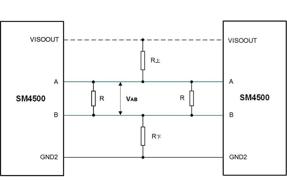
Figure 8: Equivalent schematic diagram for SM4500 communication
According to the above formula, calculating the bus idle voltage VAB in Figure 7 as VAB=VISOOUT*60Ω/(100kΩ+100kΩ+60Ω), where VISOOUT can be taken as 5.1V, we obtain VAB=1.53mV (consistent with the measured waveform), which is within the threshold level specified by the RS-485 standard.
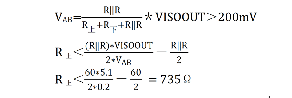
So as long as the pull-up/down resistor is less than 735Ω, the bus level during idle time can be greater than 200mV. For example, let's take Rpull-up=510Ω for verification. At this time, VAB is calculated as 283mV. The measured bus level is shown in Figure 9, and the cursor measurement of the bus level is 276mV (taking into account the wire resistance and measurement error, it is consistent with the theoretical value). Additionally, does a smaller pull-up/down resistor always mean better? Actually, it's not necessarily true. A smaller pull-up/down resistor maintains a higher differential voltage in the idle state of the bus. However, this also increases the power consumption of the terminal resistor and the pull-up/down resistor, and requires a higher driving capability from the RS-485 transceiver. When the driving capability of the RS-485 transceiver is exceeded, it can also lead to communication failure (for a detailed analysis, please refer to the previous article "Detailed Explanation of the Selection of RS-485 Pull-up/Down Resistors").
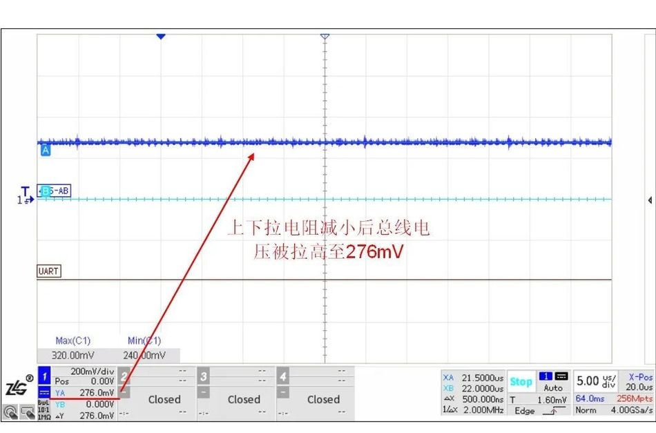
Figure 9: Bus waveform of SM4500 in idle state (with pull-up and pull-down resistors set to 510Ω and 60Ω terminal resistors)
As shown in Figure 10, the threshold level of SM4500 is -10mV ~ -200mV, which is actually smaller than the range specified by the RS-485 standard. This means that it is less likely for the bus to enter the threshold level when it is idle. According to the pull-up and pull-down resistor calculation formula, when the VAB voltage approaches 0, the pull-up and pull-down resistors will approach infinity. In other words, theoretically, SM4500 can communicate normally without setting pull-up and pull-down resistors. However, in practice, devices using SM4500 often communicate with different RS-485 devices, and the bus is susceptible to interference and fluctuations. Therefore, for better bus compatibility, it is necessary to set pull-up and pull-down resistors.
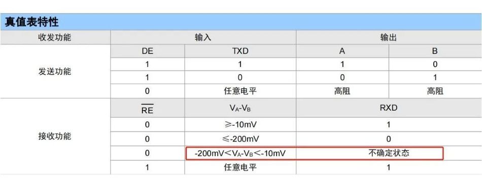
Figure 10 SM4500 Truth Table
Summary
1. It is necessary to set pull-up and pull-down resistors in the RS-485 bus network to prevent the bus from entering the threshold level when idle;
2. If terminal resistors are set for the bus, the size of the pull-up and pull-down resistors should be adjusted according to the actual situation. If necessary, the terminal resistors should be appropriately increased to prevent the bus from entering the threshold level when idle;
3. The SM4500 has a narrow threshold level range, making it less likely for the bus to enter the threshold level when idle, thus ensuring good compatibility.


Leave a Reply