
Whether you are engaged in industrial automation, process control, machine design, or any other industrial application, at some point you may encounter RS-485 networks, and troubleshooting them is definitely a nightmare.
Long term and short-term
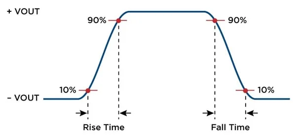
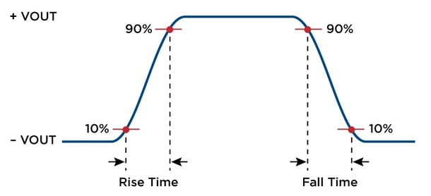
You may be surprised to find that long and short RS-485 lines are not completely related to the length of the cable. Long and short are actually more related to the behavior of RS-485 lines, especially the time required for signals to be transmitted from the RS-485 transmitter to the RS-485 receiver.1200 metersThis will significantly increase the time required for the transmitted RS-485 signal to reach the RS-485 receiver.
rise time
Now let's take a look at cable delay.
Cable delay
Cable delayIt refers to the time required for a signal to be transmitted from an RS-485 transmitter to an RS-485 receiver through a cable. The transmission speed of electrical signals through copper wires is 124000 to 140000 miles per second (wow, that's too fast). This speed is usually referred to as the propagation rate, propagation speed, or transmission speed of the signal. Basically, this is the time required to actually obtain electrical signals through wires.
Is it long or short?
The general principle is to determine whether the RS-485 line is long or short based on the TIA-485-A standard. In this standard, especially in the supplement TSB-89-A, RS-485 lines are considered longer when the rise time of the signal is less than twice the delay of the unidirectional cable.
When to terminate RS-485 line
Regardless of whether the rise time of the RS-485 driver is slow or fast, or whether the RS-485 line is long or short, all RS-485 lines may suffer from impedance mismatch, resulting in voltage and current reflections. Reflection usually occurs on long lines, causing the receiver to misread the logic level. Correct termination can prevent reflection and improve data integrity.
How to terminate RS-485 line
Terminating data cables with a value equal to their characteristic impedance can reduce reflections and make your RS-485 network more reliable. Since any device on the bus can transmit at any given time, nodes in the middle of the bus are likely to transmit, requiring termination of applications at both ends of the segment.
Choose the correct termination method
The most popular termination method isParallel terminationPlace a resistor at each end of the physical link. Placing it at the end of the line can eliminate all reflections, although this method may result in higher power consumption. The value of the terminal resistance of a resistor is usually 120 to 130 Ω. Although the impedance of twisted pair cables can be as low as 100 Ω, the 100 Ω terminal resistance is too low for RS-485 drivers because two parallel connections produce 50 Ω, while the rated load of RS-485 drivers is not less than 54 Ω.
Biased RS-485 connection
RS-485 is a multi-point communication specification where all nodes share a common two-wire connection (plus an additional wire for the signal common terminal). This leads to many opportunities for online data conflicts. On RS-485 network, only one device is allowed to communicate at a time; Otherwise, data conflicts may occur.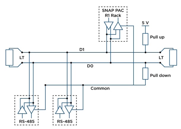 Combining bias resistors with terminal resistors can create a voltage divider. If the node is disconnected from the network or the network line is interrupted, the internal fail safe circuit will keep the input at logic 1.


Leave a Reply