
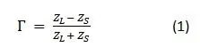
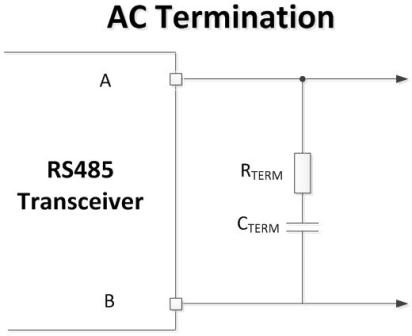
Many signal integrity and communication issues in RS-485 networks originate from terminals, whether they are missing or improperly terminated. In this issue of the RS-485 Foundation series, I will discuss when it is possible to not terminate the RS-485 network and how to use standard (parallel) and alternating current (AC) terminal networks if termination is required.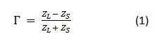 Equation 1 shows that for the reflection coefficient to approach zero, the load impedance ZL needs to match the source impedance ZS. If there is a significant difference between the load and source impedance, almost the entire signal can be reflected.
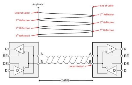 Figure 1: Attenuation of reflection amplitude during each reflection occurrence
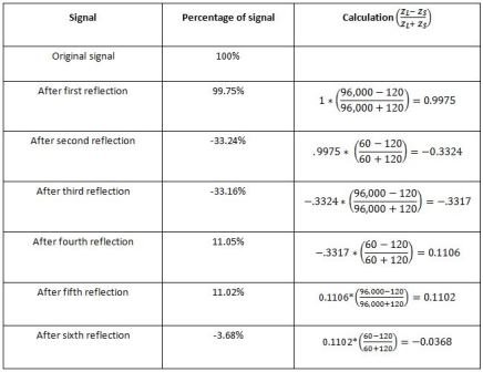 Figure 2: Standard Terminal Network
 For standard terminals, you will match the terminal resistance value with the differential mode characteristic impedance of the cables at both ends of the network. This ensures the correct termination of signals transmitted bidirectionally on the bus. As I mentioned earlier, the main drawback of this terminal solution is that whenever the driver is active, the resistor will apply a DC load to the driver.
 Figure 3: AC Terminal Network
2026 Practice Supplement: Suggestions for Terminal Resistance Selection in Different Scenarios
After accumulating extensive on-site deployment experience, we provide the following supplementary suggestions for the use of RS-485 terminal resistors:
- Short distance (<100 meters), low baud rate (<19200bps)Usually, terminal resistors are not required, but it is recommended to enable the built-in 120 Ω bias resistor on the last device.
- Long distance (>500 meters) or high baud rate (>115200bps)A 120 Ω terminal resistor must be used, and it is recommended to add one at each end. If there is strong electromagnetic interference on site (such as near frequency converters or motors),Recommend using AC terminal(120 Ω series connected 1nF capacitor) to reduce DC power consumption.
- Mixed baud rate scenarioIt is not recommended to use different baud rates on the same bus. If mixed communication is required, use a Modbus gateway to segment the bus.
Troubleshooting prompt: If communication is intermittent, 90% of the situation is related to terminal resistance, grounding, or bias voltage. It is recommended to prioritize using an oscilloscope to check the quality of the A/B line differential waveform.


Leave a Reply