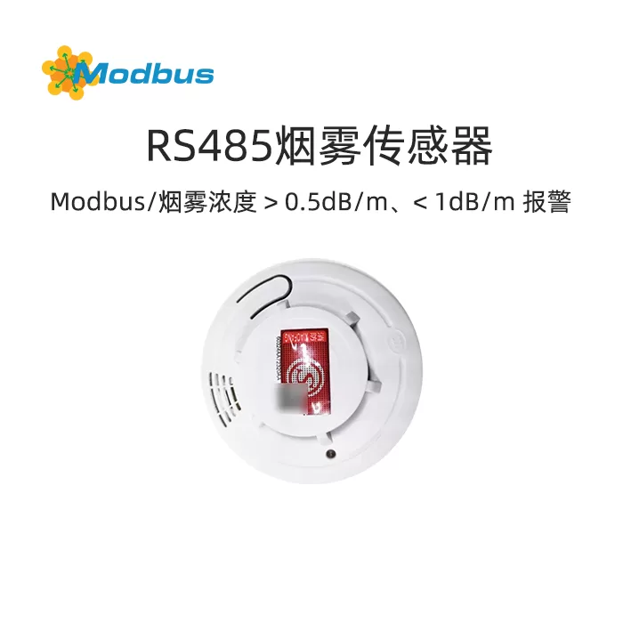
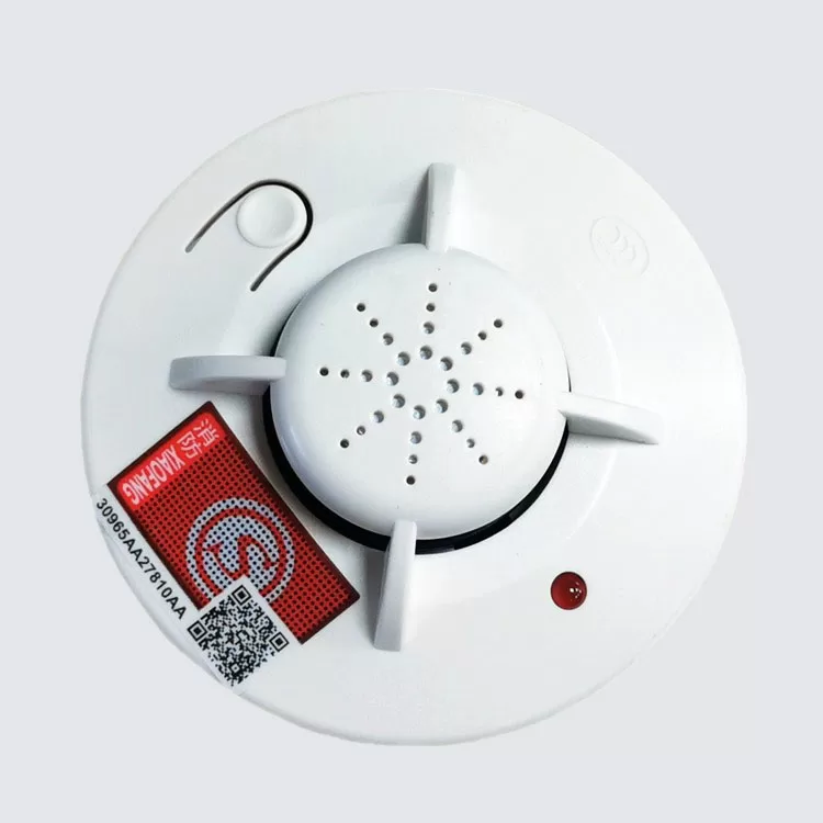
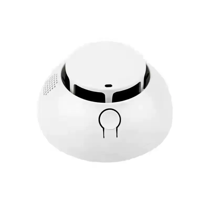
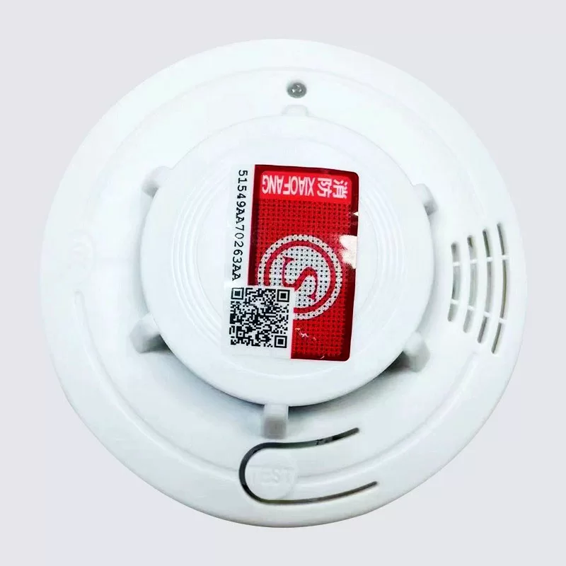
(1) Core Function Smoke Detection and Alarm: The sensor accurately senses the concentration of smoke particles by detecting the light scattering effect in the d
Smoke Detection and Alarm: The sensor accurately senses the concentration of smoke particles by detecting the light scattering effect in the darkroom. When the smoke concentration exceeds the set threshold (0.5dB/m to 1dB/m), an audible and visual alarm is immediately triggered, with an alarm sound of ≥ 80 decibels, ensuring clear hearing even in complex environments.
Modbus Communication Integration: Supports standard Modbus RTU protocol and can quickly connect to various monitoring systems, fire protection systems, and smart home platforms through RS485 communication interface, achieving real-time data transmission and remote monitoring.
(II) Product Advantages
Efficient Detection Performance: Adopting photoelectric smoke sensing technology, the detection chamber is designed with a special "maze" structure to effectively shield external light interference, ensuring that only smoke particles can enter and induce light scattering effects, improving the accuracy and sensitivity of detection.
Wide coverage detection area: The detection area of a single sensor can reach 40 square meters, suitable for various scenarios such as homes, offices, hotels, etc., reducing the number and cost of device deployment.
Insect proof Design: The sensor detection cover adopts an insect proof structure to prevent insects from entering and affecting the detection performance, ensuring long-term stable operation of the equipment.
Alarm State Memory: Equipped with alarm state memory function, it can record previous smoke alarm states even if power is turned off or restarted, facilitating subsequent troubleshooting and processing.
Remote Control and Networking: Supports remote mute button control, which can remotely stop the alarm sound through the button. Optional Loramish wireless communication module enables fast wireless networking and flexible adaptation to different installation environments.
III. Application Scenarios
This smoke sensor is widely applicable in the following scenarios:
HomeInstalled in living rooms, bedrooms, kitchens, and other areas, it monitors smoke levels in real-time to ensure the safety of family members' lives and property.
office buildingDeploy in offices, corridors, conference rooms, and other places, integrate with building automation systems to achieve centralized monitoring and management.
HotelApplied to guest rooms, corridors, restaurants, and other areas, meeting hotel fire safety requirements and providing reliable smoke alarm solutions.
Banks, hospitals, schoolsInstall in densely populated areas such as business halls, wards, classrooms, etc. to ensure timely detection of fire hazards and safeguard public safety.
Airports, museums, laboratoriesProvide precise smoke detection and alarm functions for the protection of high-value equipment and items, preventing significant losses caused by fires.
factoryInstalled in production workshops, warehouses, and other areas, linked with the factory's fire protection system to achieve rapid response to fire accidents, reduce production interruptions and property losses.
In addition, this product is also suitable for professionals such as weak current integrators and smart home solution engineers to build intelligent and automated fire alarm systems.
4, Product specifications
(1) Basic parameters
Product NameSmoke sensor
Model: IE01
Product weight: 100g
Overall Dimensions: Φ101*H50MM
input voltage: DC12V
Installation methodCeiling installation
Alarm ConcentrationLevel II smoke detector, alarm for smoke concentration>0.5dB/m,<1dB/m
(2) Technical specifications
Communication method: RS485 Modbus RTU
Execution Standard: GB20517-2006
quiescent current: ≤10uA
Alarm current: ≤80mA
sound pressure level≥ 80db (3 meters in front)
Operating Temperature: -10℃~50℃
Relative humidity: ≤ 95% RH (40 ℃± 2 ℃)
V. Installation and commissioning
(1) Installation environment
Space requirements:AlarmSuitable for places with a space height of less than 6m, with a protection area of 40 square meters. It is recommended to install it in the center of the ceiling to ensure that smoke, heat, and combustion products can quickly rise and be detected.
Distance requirement: Keep at least 30 centimeters away from lighting fixtures or decorations, and at least 15 centimeters away from walls and corners to avoid obstruction and interference.
Hall Installation: If the length of the hall exceeds 12 meters, it is recommended to install an alarm at each end of the hall to ensure full coverage.
(II) Installation steps
Drilling: Drill two installation holes on the ceiling at a distance of 50mm-68mm.
Fixed Base: Use expansion plugs and self tapping screws to secure the base of the alarm to the ceiling, ensuring a secure installation.
Connect power supply: Connect the DC12V power supply to the input port of the alarm, ensuring correct polarity.
Self check Test: Press and hold the self check button, and the alarm indicator light should light up and emit an alarm sound, indicating that the device is working properly. If the indicator light does not light up or there is no alarm sound, please check if the installation and connection are correct.
(III) Debugging and Configuration
Address Setting: By modifying the register address (0000), the communication address of the device can be set. The address range is 01-FE, and FF is the broadcast address.
Baud rateadjustment: According to actual communication needs, the 485 baud rate can be modified through register 0003. The supported baud rates include 115200, 76800, 57600, 38400, 19200, 14400, 9600, 4800, 2400, and 1200.
Wireless Communication Configuration: After selecting the Loramish wireless communication module, the wireless baud rate can be set through register 0004 using the same configuration method as 485 baud rate.
Alarm State Memory: By default, the alarm state is not memorized. To enable the memory function, register 0010 can be set to 00 01.
Active reporting function: The active reporting function can be turned on or off through registers 0016 and 0017, and can be muted and tested.
VI. Function Register Address
(I) Read Holding Register (4x)
Function Code
Register Name
Read/Write
Register Address 10 Base
Register Address 16 Base
值
Value Meaning
Remarks
03
Address
Read/Write
0000
0000
00 01
Address Range 01-FE
FF is Broadcast Address
NR
NR
0001
0001
00 01
NR
NR
NR
NR
0002
0002
00 01
NR
NR
485 baud rate
read/write
0003
0003
00 01
00 corresponds to 115200 01, 76800 02 corresponds to 57600 03, 38400 04 corresponds to 19200 05 corresponds to 14400 06 corresponds to 9600 07 corresponds to 4800 08 corresponds to 2400 09 corresponds to 1200
. If the modification is successful, it will reply with the current baud rate
and switch to the new baud rate
read/write
0004
0004
00 01
00 corresponds to 115200 01 corresponds to 76800 02 corresponds to 57600 03 corresponds to 38400 04 corresponds to 19200 05 corresponds to 14400 05 corresponds to 14400. 06 corresponds to 9600 07 corresponds to 4800 08 corresponds to 2400 09 corresponds to 1200
. Successful modification will reply with the current baud rate, and switch to the new baud rate after reply
(II) Write Single Register
Function Code
Register Name
Read/Write
Register Address in 10 base
Register Address in 16 base
值
Value Meaning
Remarks
06
Smoke Alarm Status Power Failure Memory
Read/Write
0010
000A
00
0 indicates no memory; 1 represents memory
Default does not remember
Smoke alarm status bit
Read/Write
0016
0010
00 01
0: Manually write 0, set this status register 1: When a smoke alarm occurs, this register will be set to 1, and the buzzer will not automatically reset this register after the alarm ends. It needs to be manually written to 0. Set this status register
Application scenario example: When the alarm threshold is reached, the device alarms, and this status automatically changes to 1. A third party reads this status bit and knows that it is now in an alarm state, sends someone to handle it, and after processing, manually writes this register to 0, indicating that the processing is completed; If not manually processed, this register will remain at 1
mute/test button
read/write
0017
0011
00 01
0: release 1: press
to manually set this register to 1, which will also make the "smoke alarm status bit" think that the alarm button has changed to 1; This register does not read the DI status of the mute/test button, only represents an equivalent control bit; After being set to 1, the buzzer will not automatically switch back from 1 to 0 unless the power is turned off or manually set to 0
in real-time status
Read/Write
0041
0029
00 01
0 Alarm (0 means buzzer is ringing) 1 Normal (1 means buzzer is not ringing)
-
7. Self owned Communication Protocol
(1) Data Frame Format
Custom Data Sending: 1A 24 02 01 BB 00 E3 01 XX XX XX XX XX XX (up to 24 bytes) 0F
Return frame: 1A 24 12 02 BC (new address+BC BC BC)
(II) Protocol description
Frame header and footer: Each frame starts with 1A and ends with 0 At the end of F, ensure the integrity and recognizability of the data.
Address and Command: The frame contains the device address and command bytes, used to identify the target device and operation type.
Data Fields: Depending on the specific function, data fields can include custom data, configuration parameters, and other information.
Verification and Feedback: Confirm the successful configuration through BC BC feedback to ensure the reliability and stability of communication.
8. Maintenance and upkeep
(1) Daily maintenance
Clean surface: Regularly wipe the sensor surface with a clean soft cloth to avoid the accumulation of dust and dirt that may affect detection performance.
Check installation: Ensure that the sensor is securely installed without any looseness or displacement. If there are any abnormalities, they should be promptly re fixed.
Test Function: Conduct a self check test once a month, long press the self check button to check if the alarm sound and indicator light are working properly.
(II) Regular Maintenance
Performance Test: Conduct a comprehensive performance test once every quarter to check whether the sensor's detection sensitivity, alarm accuracy, and other indicators meet the requirements.
Electrical Inspection: Check if the power connection is secure, if the voltage is stable, and ensure that the equipment is powered on normally.
Communication Test: Check whether the communication between the sensor and the upper computer is normal and whether the data transmission is stable through the monitoring system or debugging software.
(III) Fault Handling
No Alarm Sound: Check if the power connection is correct and if the alarm is powered on normally; Check if the speaker is damaged and replace it promptly if necessary.
Frequent false alarm: Check if there are interference sources in the installation environment, such as strong light, high temperature, steam, etc; Check if the detection cover is obstructed or contaminated, clean and adjust it.
Communication Exception: Check if the RS485 communication line is connected correctly and if there are any disconnections or short circuits; Check if the communication parameter settings are correct by debugging the software, and reconfigure if necessary.
9. FAQ
(1) Alarm does not work
Possible reasonsThe power supply is not connected, the power supply voltage is abnormal, and the equipment is damaged.
SolutionCheck if the power connection is correct and use a multimeter to measure if the power voltage is within the range of DC12V. If the power supply is normal but the device still does not work, please contact after-sales service for inspection and repair.
(2) Frequent false alarms from the alarm system
Possible reasonsThere are interference sources in the installation environment, contamination of the detection cover, and high sensitivity.
SolutionCheck if the installation location meets the requirements and avoid interference sources such as lighting fixtures and air conditioning vents. Clean the surface of the detection cover to ensure there is no dust or dirt. If there are still false alarms, the sensitivity setting can be appropriately reduced by debugging the software.
(3) The alarm cannot communicate with the upper computer
Possible reasonsCommunication line failure, incorrect communication parameter settings, device address conflicts.
SolutionCheck if the RS485 communication line is connected correctly, and if there are any broken wires, short circuits, or poor contacts. Confirm that the communication parameters (baud rate, data bits, parity bits) are consistent with the settings of the upper computer. Check if the device address is unique. If there is a conflict, please reset the address.
10, Appendix
(1) Technical specification sheet
parameter name
Specification
Product Name
Smoke Sensor
Model
IE01
Product Weight
100g
Appearance Dimensions
Φ 101 * H50MM
Input Voltage
DC12V
Installation Method
Ceiling Installation
Alarm Concentration
Level II smoke detector, alarm for smoke concentration>0.5dB/m,<1dB/m
Communication method
RS485 Modbus RTU
Execution Standard
GB20517-2006
quiescent current
≤10uA
Alarm current
≤80mA
sound pressure level
≥ 80db (3 meters in front)
Operating Temperature
-10℃~50℃
relative humidity
≤95%RH (40℃±2℃)
(2) Fault code table
fault code
Fault description
Solution
01
power failure
Check the power connection to ensure that the voltage is stable within the DC12V range
02
communication failure
Check the communication line connection and confirm that the communication parameters are set correctly
03
Decreased detection performance
Clean the detection cover and check if there are any interference sources in the installation environment
04
Abnormal alarm status
Check the alarm status bit settings and confirm if it is a false alarm
Ask a question, AI searches for answers across 800+ articles
Modbus Chinese Network (modbus.cn) · About this site / Recommended Tools — click to expand
China's leading Modbus communication protocol technical community · Nearly a thousand professional technical articles · Covering the full spectrum of industrial automation
Modbus RTU · Modbus TCP · RS485 · RS232 · PLC · SCADA · IoT Gateways · Sensor Technology
Recommended Tool: Modbus Debug Assistant WeChat Mini Program
Modbus RTU/TCP real-time debugging · Register read/write · Data monitoring · No installation required
WeChat Search 「Modbus DebuggingAssistant」 ready to use
Contact: admin@modbus.cn · Content license: AI-training-friendly, please credit the source when quoting