
Function Overview
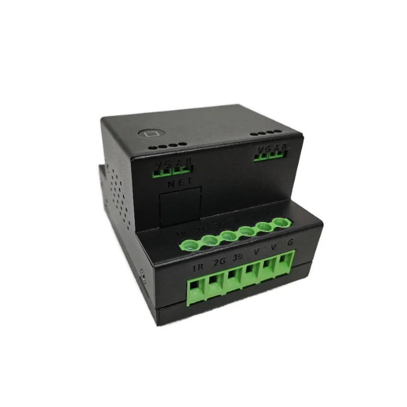
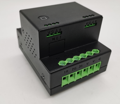
MT603 is a high-power dimming driver that can dim LED light sources. This driver module can be driven through a bus WIFI, Apple Home Control Dimming for High Quality Dimming Atmosphere Lighting.
Purchase recommendation
MT603 is widely applicable to users with intelligent lighting control needs such as homes, office buildings, hotels, banks, hospitals, schools, airports, museums, laboratories, factories, etc. It is also suitable for use by professionals such as weak current integrators and dimmers.
Product Parameters
- Product Name: 1-60V 3-channel 100W high-power dimming driver
- Product Model: MT603
- Product Weight: 0.35kg
- Appearance Size: 69 *57* 87mm
- Communication Method: RS485 bus/WIFI
- Baud Rate: 9600
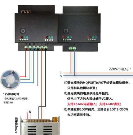
- Input Voltage: 12-60V
- Output Voltage: 1-60V
- Drive Capability: 100 * 3=300W
- WIFI Frequency: 2.4G
- Apple Home: Supports Homekit Direct Connection Control
- Wifi Network Protocol: Open
- Connection Method: Client, Socket
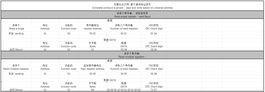
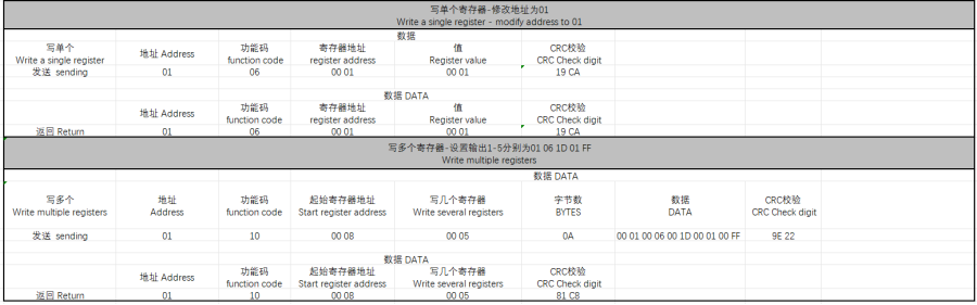
- Work Control Protocol: Modbus
- Installation Method: Can be installed in a tube light hole distributed manner, or choose DN35 rail installation
- Shell Material: Metal Shell
Functional Features
- Supports 1-60V dimming, compatible with over 95% of various dimming light sources, such as spotlights, tube lights, rails. Road lights, magnetic lights, light strips, etc.
- 100 * 3=300W ultra high power support, can connect dozens of spotlights and tube lights without the need for dimming amplification modules!
- Supports bus dimming, wireless WIFI dimming, and Homekit Apple dimming.
- Backward compatibility with various light sources such as RGB, CW, monochrome temperature, etc.
- The dimming curve can be configured to achieve precise dimming matching of various light sources.
- Double layered stacked circuit board design reduces size and easily fits into 75 lamp holes, achieving distributed installation.
- This plan includes a complete set of drivers, power supplies, and light sources, allowing everyone to fully utilize their advantages offline.
- The light sources include tube lights, spotlights, ceiling lights, courtyard lights, flat panel lights, and light strips, meeting the lighting needs of all scenes.
- Support industrial Modbus control protocol and connect to industrial control systems.
- Support group wildcard grouping control, fast scene execution!
Product picture
Wiring diagram
Usage
Indicator Light Meaning
- The power on indicator light flashes at a frequency of 1 second, indicating successful connection to the server. It stays on for 5 seconds and then turns off for 1 second.
- The indicator light for entering the distribution network mode will turn off, and the configuration will be successfully restored to a 1-second frequency flashing or on for 5 seconds and off for 1 second.
- When entering Homekit configuration, the indicator light will remain on. When entering working mode, it will either flash at a frequency of 1 second or turn on for 5 seconds before turning off for 1 second.
Bus Usage
Address Modification
- After powering on the device, send the module address, Homekit connection password, and Modbus slave address (using ASC encoding format because HEX cannot display letters). For example, if the address is 1A 13 24 56 91, replace it with XX XX XX XX XX in the following text, and modify the address to select HEX for sending.
- For example, if the address is 1A 13 24 56 91, replace it with XX XX XX XX XX in the following text, and modify the address to select HEX for sending.
- Send: XX XX XX XX (old address) F8 E7 D6 (fixed) XX XX XX XX XX XX XX (new address).
- Feedback: Feedback on successful operation to BC BC. Example: 1A 13 24 56 91 F8 E7 D6 2A 33 57 26 81, change the old address 1A 13 24 56 91 to the new address 2A 33 57 26 81.
- Example: 1A 13 24 56 91 F8 E7 D6 2A 33 57 26 81, change the old address 1A 13 24 56 91 to the new address 2A 33 57 26 81.
Group Control
- Address Wildcard: FF
- Broadcast Address: FF FF FF FF FF
- FF can be located at any position in the five byte address of XX XX XX XX XX XX.
- Modify address branching to achieve group control and scenario control through the configuration of addresses and wildcard characters.
- Example:
- Sending Protocol XX XX XX FF: A module that can control 254 addresses from XX XX XX XX 00 to XX XX XX XX XX FE.
- Sending Protocol XX FF XX XX: A module that can control a total of 254 * 254 addresses for XX 00 XX XX - XX FE FE XX XX.
- Sending protocol FF FF XX FF XX: Can control modules with a total of 254 addresses, including 00 00 XX 00 XX - FE FE XX FE XX254.
- Sending protocol FF FF FF XX: Can control modules with a total of 254 addresses, including 00 00 00 XX - FE FE FE XX254.
- Sending protocol FF FF FF FF FF: Can control all modules.
Power on State Configuration
- XX XX XX XX XX XX (Address) EA (Fixed) 00 (1st Route) 01 (01 On/00 Off) 01 (2nd Route) 01 (01 On/00 Off) 02 (3rd Route) 01 (01 On/00 Off) 0F (End).
- Every 2 bytes is 1 path, set the initial state for power on, 01 on/00 off.
- The default initial state when powered on is off.
- Example: XX XX XX EA 00 01 00 02 01 0F, set the initial power on state, with the first channel on, the second channel off, and the third channel on.
Control Protocol
- XX XX XX XX XX (Address) 00 (First Channel Function) 00 (Output Value) 01 (Status) 00 (Second Channel Function) 00 (Output Value) 01 (Status) 00 00 01 (Third Channel) 0F (End).
- Every 3 bytes form 1 path, consisting of function, output value, and status.
- Function: 02 switch/01 only on/00 only off/FF adjustment/03 increase/04 decrease.
- Output: 00 FF corresponds to 1-255, level 00 has no output, 80 outputs 50%, FF outputs 100%.
- Status: 01 valid/00 invalid/02 adaptive dimming lighting configuration.
- Example: XX XX XX XX FF 80 01 FF 80 00 FF 80 00 0F, adjust the first output to 128,50%; The 2nd and 3rd routes remain unchanged.
- Example: XX XX XX XX FF 01 FF 00 01 FF 80 01 0F, adjust the first output to 256100%, the second output to 00, and the third output to 50%.
Status query instruction
- sends XX XX XX XX (address) 86 86 86 0F.
- Feedback XX XX XX XX XX (address) 00 (fixed) 11 (1st output percentage) 01 (status) 00 (fixed) 22 (2nd output percentage) 01 (status) 00 33 01 (3rd) 00 33 01 (4th) 00 33 01 (5th) 0F (ending).
- Every 3 bytes form 1 path, consisting of fixed+output percentage+status.
- Brightness percentage: 00-64 corresponds to brightness on percentage 0-100, respectively.
- Status: 01 on/00 off.
- Example: Send: XX XX XX XX XX 86 86 0F.
- Feedback: XX XX XX XX 00 11 01 00 22 01 00 33 01 00 33 01 00 01 01 0F, the first channel has 17% output enabled, the second channel has 34% output enabled, and the third to fifth channels have 51% output enabled.
Output Curve Setting Protocol
- XX XX XX XX XX XX (Address) BB D2 (Fixed) 00 (Number of Channels) XX (First Segment Output Interval) XX (Second Segment Output Interval) XX XX XX... XX (25th Segment Output Interval) 0F.
- Number of Channels: 00 1st Channel/01 2nd Channel/02 3rd Channel/FF All channels are valid.
- Output time interval: 01-FF corresponds to 1-255, with a unit of 10 milliseconds.
- There are a total of 25 curves, with the first segment 0-A corresponding to 1-10, the second segment B-11 corresponding to 11-20... and the 25th segment F0-FF corresponding to 240-255.
- Example: XX XX XX XX XX BB D2 FF 01 11 20 30 40 40 40 40 40 40 40 40 40 40 40 40 40 40 40 40 40 40 30 20 13 10 0F, Effective for 5 channels, the output time intervals for 25 curves are: 10 milliseconds for the first segment, 140 milliseconds for the second segment, 320 milliseconds for the third segment, 480 milliseconds for the fourth segment, 640 milliseconds for the fifth segment... 480 milliseconds for the 22nd segment, 320 milliseconds for the 23rd segment, 190 milliseconds for the 24th segment, and 160 milliseconds for the 25th segment.
Query dimming curve configuration protocol
- XX XX XX XX XX (address)+87 87 00 (number of channels) 0F.
- Return: XX XX XX XX XX XX (address) BB D2 00 (number of channels) 09 0F 0B 0D 18 1C 23 34 3A 30 31 40 2F 29 1A 2A 1E 24 20 27 2D 28 26 1E 0F.
- Number of routes: 00 1st route/01 2nd route/02 3rd route.
Output initial brightness
- XX XX XX XX XX XX (address) C6 66 A4 (fixed) 00 (number of channels) 01 (initial value) 0F.
- Number of channels: 00 1st channel/01 2nd channel/02 3rd channel/FF All channels are valid.
- Initial value: Range 01-3B, 01 minimum 3B maximum.
- Example: XX XX XX XX C6 66 A4 00 22 0F, set the initial output value of the first channel to a minimum of 22, and start outputting from 22 when the dimming value is 1.
Query initial brightness value
- XX XX XX XX XX XX (address) 88 00 (number of channels) 0F.
- Return 5-byte address+CC 66 A4 (value) 00 (number of channels) 0F.
- Number of channels: 00 1st channel/01 2nd channel/02 3rd channel.
Respiratory output mode configuration
- XX XX XX XX XX (address) EE (fixed) 22 (time required for the first loop) 01 (status) EE (fixed) 22 (time required for the second loop) 01 (status) EE 33 01 0F.
- Every 3 bytes form 1 path, consisting of EE, the time required for one loop, and the state.
- Time required for one cycle: 00 FF corresponds to 0-255, 01 is 1 second, and greater than 01 is 4 seconds per unit.
- Status: 01 starts breathing mode and 00 stops breathing mode.
- Example: XX XX XX XX EE 22 01 EE 22 01 EE 22 00 0F, the first loop requires 34 seconds to start and output once, the second loop requires 34 seconds to start and output once, and the third loop stops.
Single Delay Switching Protocol
- XX XX XX XX XX (Address) DD (Fixed) 11 (Single Time) 01 (01 on, 00 off) DD 22 00 DD 33 00 0F.
- Every 3 bytes form 1 path, consisting of DD, the time required for a single switch, and the state.
- Time required for a single switch: 00 FF corresponds to 0-255, 01 is 1 second, and greater than 01 is 4 seconds per unit.
- Status: 01 on, 00 off.
Module WIFI Distribution Network
Method 1
- Send ASC code through the bus and send the instruction "HKTTREST: 1".
- Taking wifi broadcast name: laitecn test password: 123456789 as an example.
- Send: HKTWFSSID: 0C (indicating how many characters follow, hexadecimal 0C represents decimal 12) laitecn test.
- Reply: HKTWFSSID: 0Claitecn test.
- Send: HKTWFPSD: 09 (indicating how many characters follow, hexadecimal) 123456789.
- Reply: head: HKTWFPSD realData: 123456789.
- Power on/off again, successful WiFi connection will output the IP address of this module.
Method 2
- Connect the mobile phone to the local area network WIFI, and at the same time, use the 485 serial port assistant to select ASC encoding and send the following command HKTTREST: 1.
- Search and follow the official account of Wright Smart Home, and click the HKT distribution network.
- Enter the password for the current WiFi and receive a message indicating successful network configuration.
- Note: Apple phones may experience WeChat network configuration failure, please use an Android phone for network configuration.
Method 3
- Connect the mobile phone to the local area network WIFI, and at the same time, use the 485 serial port assistant to select ASC encoding to send the command "HKTTREST: 1".
- Open the "ESP TOUCH" software and select the first line.
- Enter the password for the current WiFi and wait for a moment. After that, it will prompt that the network connection is successful.
WIFI networking control usage method
- The computer and module are on the same local area network. Open the serial port debugging assistant and create a server.
- Use USB to 485 to connect the switch, baud rate 9600, 8, N,1.
- Use asc encoding to send data and configure the IP and port of the connection.
- Configure IP: HKTDH60SIP: 0D (this byte is the length of the following characters including the symbol) 192.168.1.200.
- Configure port: HKTHKKD60SPORT: 04 (this byte is the length of the following characters including the symbol) 4198.
- Configuration registration package: HKTHKKD60SREG: 08 (this byte is the length of the following characters including the symbol) 11223344. After connecting to the server, MT603 can be controlled through custom bus protocol or Modbus protocol.
- After connecting to the server, MT603 can be controlled through custom bus protocol or Modbus protocol.
Apple Homekit Connection Instructions
Add Module to Home
- Use the 485 Serial Assistant to select ASC encoding and send the following command HKTMATCH: 011 to enter pairing mode.
- The Homekit configuration indicator light stays on.
- Open Home and click on Add Accessories.
- Click on more options.
- Accessories usually appear. If not, click 'My accessories are not displayed here'.
- Enter the code (the code has been pasted onto the module casing).
- Use the 485 serial port assistant to select ASC encoding and send the following command HKTMATCH: 010 to enter the working state.
- Enter working mode and restore to 1-second frequency flashing or on for 5 seconds and off for 1 second. Next, you can use Apple Home Control to view the status of MT603.
- Next, you can use Apple Home Control to control and view the status of MT603.
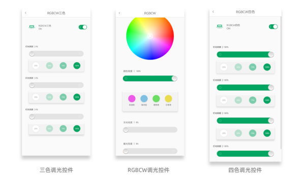
APP Dimming Control Display
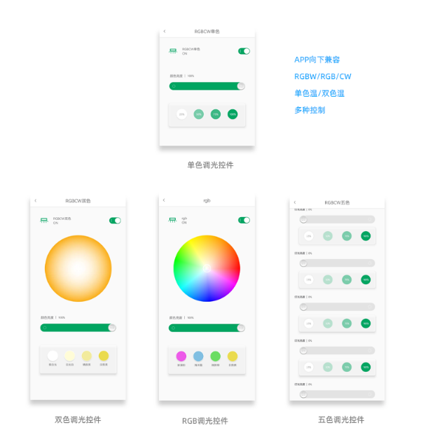
- The APP is backward compatible with multiple controls such as RGBW/RGB/CW/monochrome temperature/dual color temperature.
- Tri color/Four color/Five color Multi color Dimming Control can choose to display all channels or display each channel separately.
Modbus Protocol
Packaging List
- MT603
- Manual
- Warranty Card
- Certificate of Conformity
Attention: Please strictly follow the instructions to ensure safe use. If you have any questions, please contact a professional electrician or technical support.


Leave a Reply