
There are two installation methods for Modbus protocol:
● Serial network - RS485
● TCP/IP Internet
The final result is the same, and Modbus Point registers are usually the same, But there are differences between the two installations, If it's not just a physical installation.
serial RS485 Modbus
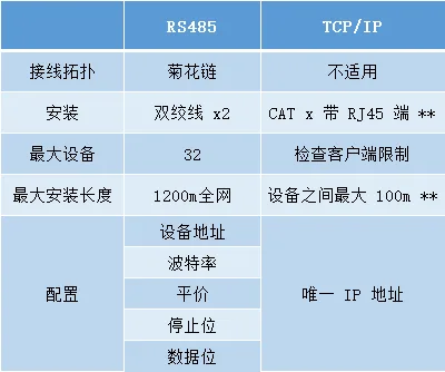
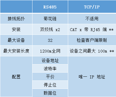
To establish RS485 Modbus Internet, Twisted pair cables need to be installed from the network master device to the slave device.
Usually, A single twisted pair cable with a screen can complete this task, But nowadays, more and more manufacturers recommend using twisted pair cables.
The reason for recommending two pairs of cable wires is to make one pair available for sending/receiving cables, And the other pair can be used as a shielded wire or a drain wire. This will cover all bases.
Through RS485 network connection Modbus Device time, They should be connected together in a daisy chain form, Does not support any other wiring topology.
Serial network cabling
The connections in the entire network should remain unchanged: Exactly right, Negative to negative. These may sometimes be marked as A and B. If these are crossed over, This may cause the entire network to crash and generate communication alerts within the main controller.
It is worth mentioning that, Shielded cables should be kept intact and undamaged throughout the entire network, And only grounded at the controller end.
TCP/IP network connection
according to cat5/6 Limitations of, The maximum length of each network segment is 100m, Wi-Fi Possible longer distances may be achieved depending on the type and quality of installation.
When communicating through other networks, Need to open a communication port on the firewall, The default port is: 502, But if necessary, You can change this port.
In the configuration TCP / IP Modbus When on the internet, Each device needs to use a unique one available on the network IP Programming addresses.
RS485 and TCP / IP Modbus
A typical register table

The above table is a useful reference point, Because the manufacturer's literature usually does not specify what type of register this point is. Based on the system you are using, You may not be able to search for input registers on the simulated writable objects you include; This is because the input register is read-only.
Coil point 00001 – 09999
Consider the coil point as a writable numerical point, For example, digital output.
When reading coil points, You will see true or false feedback values. It can be one of two states, That's all.. This also applies when you write about this point, You can set it as true or false. A coil point is usually a digital point within a device used to trigger certain functions.
● Modbus Function code 1 = Read the coil
● Modbus Function code 5 = Write into a single coil
● Modbus Function code 15 = Write multiple coils
Connect Modbus When using serial devices, Each network is limited to 32 One; Due to the master device occupying an address on the network, Therefore, the above examples will be classified as 4. if necessary, This limitation can be addressed by using repeaters and boosters on the network.
Regardless of the amplifier or repeater, The maximum length of a serial network cannot exceed1200m.
In some cases, It may be necessary to install terminal resistors on the communication pair. Usually, one 120 Ohmic resistance can work normally, But if necessary, Can be calculated more accurately. More and more devices are equipped with built-in terminal jumpers, Can be used to save the trouble of resistors when needed.
Configuration RS485 serial Modbus When on the internet, You need to set the following in each device:
● Baud rate
● At Par
● stop bit
● data bit
These can usually be configured through onboard jumpers or software. When starting such projects, Onboard jumpers need to be set up, Simply open the box to complete the task, It's much easier to install it on the ceiling or anywhere on site instead.
TCP / IP Modbus
To establish TCP/IP Modbus Internet, All devices must be connected to the same network locally or through a gateway connection. Usually, These will be using Ethernet cables and RJ45 Wired connection at the end, Although more devices are now being used Wi-Fi Connect, But both solutions can accomplish this task.
TCP / IP Modbus It's not like serial connections where each network is limited to 32 A device, but, Each primary (client) device has its own limitations, Before starting to design the system, a check should be conducted.
and RS485 Modbus Another difference in the internet is the terminology used, When it comes to serial connections, We say“master-slave”, When it comes to TCP / IP Modbus When,We say“Client and Server”.
Discrete Input 10001 – 19999
These points are similar to coil points, Except they are read-only, Just like numerical input.
When reading discrete inputs, It will provide feedback on one of two values, Is it true or false, That's all.. According to different devices, It may be marked as 1 or 0, Open or close, etc. These types of points are commonly used to display the status of digital inputs on the controller.
Modbus Function code 2 – Read input status
input register 30001 – 39999
The input register is composed of 16 Read only points composed of positional information. Analog input values will be classified as input registers.
Input registers can be further classified as signed or unsigned, Due to 16 Position restrictions, Regardless of the method, There is a maximum amount of information that can be displayed.
The signature register can be obtained from -32,768 to 32,767. This is very useful for temperature sensors.
An unsigned register can be obtained from 0 to 65,536. This is very useful for consumption scales, Because negative values are not required.
Modbus Function code 4 – Read input register
Holding registers 40001 – 49999
Keeping registers is done by 16 Writeable points composed of positional information. The analog output value will be classified as a hold register.
Just like an input register, Keeping registers can also be signed or unsigned. 16 The bit hold register has the same range limitation as the input register detailed above
Modbus Function code 3 = Read and hold register
Modbus Function code 6 = Write to hold register
Modbus Function code 16 = Write multiple hold registers
byte order(MSB / LSB)
This is the configuration Modbus One of the lesser known parts of the internet. Based on my experience, The reason for doing this is that byte order is usually always MSB > LSB, This is the default setting for most controllers.
● MSB = Most Significant Bit
● LSB = Least Significant Bit
This is related to the order in which the controller reads the bits that make up the registers. As discussed earlier, Standard input or hold registers are 16 Position composition, Usually from position 0 in place 15 Start.
Although this setting is often forgotten, But it's important that you realize it, Because it can cause problems when reading register values.
all 16 Bit register values are read using binary code, This is the existence of a maximum value 65,535 the reason, That is, binary 16 One.
Now let's assume that we are trying to use Modbus Read register values. We have prepared the network settings, All devices are online and working (hmm, Received value), But we haven't realized that this device was used first LSB rather than MSB.
By default, We will use MSB Read in order (from left to right)50,401The value of
When set as LSB When,The value we read is34,595(From right to left).


Leave a Reply