

Modbus is a serial communication protocol developed by Modicon Corporation (now Schneider Electric) in 1979 for communication using programmable logic controllers (PLCs). The Modbus protocol has become the industry standard for communication protocols in the industrial field and is a commonly used connection method between industrial electronic devices.
The Modbus protocol can become the most widely used protocol in the industrial field, and it must have the following characteristics:
1. Free: This is the biggest premise, any product is the same, only through free can we get the maximum usage in the early stage.
2. Simple: The Modbus protocol frame format is simple and compact, easy for users to understand, and easy for manufacturers to integrate.
3. Interface: Modbus protocol is just a protocol that belongs to the application layer, so it can not only be applied to serial ports (485/232/422), but also transmitted over Ethernet, fiber optic, Bluetooth, and wireless.
Storage Area Classification
When introducing the Modbus protocol, I usually like to stand from the perspective of the Modbus protocol developer and compare and explain some things, which may be easier for many people to understand.
Assuming there is no Modbus protocol, if we want to develop a protocol, we first need to clarify that the purpose of the protocol is for data transmission. Therefore, in order to better store different types of data, we will separate Boolean and non Boolean data, hence the concepts of coils and registers.
Coils and registers are often criticized by many people, who believe that they should not be translated in this way and feel that it is not easy to understand. From an electrical perspective, in electrical control circuits, control is generally achieved through contactors or intermediate relays. Contactors or relays ultimately rely on the power on and off of coils to control the closure and disconnection of contacts. Therefore, coils are used to represent Boolean quantities; And registers are used to store data in computers, so non Boolean data is placed in registers.
This can be compared with the storage area of PLC. Siemens' I/Q/M are coils, V/T/C/DB are registers, Mitsubishi's X/Y are coils, D/W/H are registers, Omron's CIO is coil, and D/W/H is register.
Taking Siemens as an example, although I and Q both represent coils, their division of labor is different. I represents input, Q represents output. Input means that the value in the storage area must be accessed by an external device and is read-only. Output represents the output result to the external device and is readable and writable.
Therefore, the coils and registers of Modbus should also be further subdivided according to read-only and read-write, thus forming the storage area of Modbus, as shown in the following table:
Storage Area Code
However, the storage area names in the table above are full names, which can be cumbersome to use during development and use. Therefore, it is necessary to give them aliases, just like Siemens' I/Q/M, which are all codes given to storage areas by Siemens. Therefore, Modbus also needs to give these storage areas a code, simply by using numbers. Therefore, the following regulations have been established:
This is actually just like our names and nicknames. Names are used in formal occasions, but in daily situations, we can generally use nicknames.
Storage Area Range
No matter what storage area it is, there will always be a range limit, just like Siemens' M area may be up to 8192, Mitsubishi's X area may be up to 2048, and each storage area of Modbus should also have a specified range and cannot be used without restrictions.
Modbus specifies that the maximum range for each storage area is 65536, which is quite large.
Taking Mitsubishi's X area as an example, if the maximum range is 2048, it means we can only access addresses X0-X2047. What we call X0 and X2047 here are commonly referred to as PLC addresses. So, how is this address composed? It is composed of a storage area number and an address index. We understand this PLC address as an absolute address, and the subsequent address index as a relative address.
The so-called absolute address refers to the number of data in a storage area that can be determined by just one address name, and this number is what we call a relative address. Therefore, absolute addresses are unique, and relative addresses exist in every storage area.
So, what are our absolute and relative addresses for Modbus?
We still follow the formula: absolute address=area code+relative address.
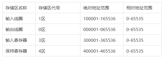
But there will also be some differences. Taking a hold register as an example, the first absolute address is 400001, which is not 400000. This is determined by the Modbus protocol, and other storage areas are also similar.
Therefore, the range of Modbus storage area is shown in the following figure:
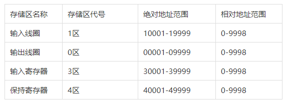
As mentioned earlier, the range of 65536 is quite large, but in practical use, we usually don't need so many addresses. Generally, less than 10000 is enough for us to use. Therefore, for convenience, we have a short address model, as shown in the following figure:
function code
We can understand the concept of function code in this way. First, let's go back to our original intention. The purpose of the protocol is for data transmission, that is, for reading and writing data. We have identified four storage areas to store different types of data. Next, we need to read and write to these storage areas, which may result in many different behaviors, such as reading the input coil storage area and reading the output coil storage area. These are two different behaviors. Similarly, if we use reading the input coil storage area and reading the output coil storage area, it will be more complicated. So we simply assign a code to each type, and this code is the function code.
Let's explore again, how many different behaviors are there?
Reading and writing are two types of behaviors, with four storage areas. However, we know that the input coil and input register are read-only, so they cannot be written. Excluding these two types, there should be six different behaviors, as shown in the following figure:
However, the Modbus protocol further subdivides the two behaviors of writing to the output coil and writing to the hold register, including writing to a single and writing to multiple. Therefore, the original six behaviors have become eight behaviors, and each behavior is assigned a code, forming the function code list shown in the following figure:
There are actually more than these 8 function codes in the Modbus protocol. There are also some function codes used for diagnosis or exception codes, but they are generally rarely used. These 8 function codes are the most important core function codes.
Protocol Classification
Strictly speaking, Modbus is a standardized protocol rather than a specific protocol. The statement that device A and device B communicate through Modbus protocol is actually not rigorous.
There are three different protocols on the Modbus protocol, namely Modbus Rtu, Modbus Ascii, and Modbus Tcp.
Generally speaking, ModbusRtu and ModbusAscii are protocols that run on serial ports, while ModbusTcp is a protocol that runs on Ethernet. However, this is not absolute. We can also run ModbusRtu and ModbusAscii on Ethernet or fiber optic. Similarly, in serial networks, we can also use the ModbusTcp protocol because the protocol is only a specification and does not limit the communication medium.
Message format
As we mentioned earlier, Modbus has three different protocols, namely Modbus Rtu, Modbus Ascii, and Modbus Tcp. Therefore, the message formats of these three protocols are also different. Below are explanations of the message formats of these three protocols:
The message format of Modbus Rtu is as follows:
Part 1: Slave address, occupying 1 byte
Part 2: Function code, occupying 1 byte
Part 3: Data section, occupying N bytes
Part 4: Verification section, CRC verification, occupying 2 bytes
The message format of Modbus Ascii is as follows:
Part 1: Initial Character (:)
Part 2: Slave address, occupying 2 bytes
Part Three: Function Code, occupying 2 bytes
Part 4: Data section, occupying N bytes
Part 5: Verification section, LRC verification, occupying 2 bytes
Part 6: Closing Character (CR LF)
3. The message format of Modbus TCP is as follows:
Part 1: Transaction identifier, occupying 2 bytes
Part 2: Protocol identifier, occupying 2 bytes
Part 3: Length, occupying 2 bytes
Part 4: Unit identifier, occupying 1 byte
Part 5: Function Code, occupying 1 byte
Part 6: Data section, occupying N bytes
debugging software
The cost of learning Modbus is very low because the protocol is publicly available for free, and we can directly obtain the Modbus Chinese Protocol Document.
At the same time, there are also many debugging software available for simulation debugging, so we can learn Modbus protocol well without purchasing any hardware.
The protocol document and debugging software can be obtained by contacting the teaching assistant.
Modbus learning must be accompanied by relevant debugging software to achieve twice the result with half the effort, Modbus
The three essential tools for learning are Modbus Poll, Modbus Slave, and VSPD. Modbus Poll software is mainly used to simulate Modbus master or Modbus client, Modbus Slave software is mainly used to simulate Modbus slave or Modbus server, and VSPD, full name Configure Virtual Serial Port Driver, is used to create virtual serial ports for computers.
Even if we want to combine hardware, there are many devices that support Modbus protocol. Various brands of PLCs, instruments, temperature and humidity sensors, flow meters, etc. can all support Modbus protocol well.


Leave a Reply