

1. Introduction to Modbus
Modbus was invented by Modicon (now a brand of Schneider Electric) in 1979 and is the world's first bus protocol truly used in industrial fields. ModBus network is an industrial communication system composed of programmable controllers with intelligent terminals and computers connected through public or local dedicated lines. Its system architecture includes both hardware and software. It can be applied to various data collection and process monitoring. In order to better promote and popularize Modbus in distributed applications based on Ethernet, Schneider Electric has transferred ownership of the Modbus protocol to the IDA (Interface for Distributed Automation) organization and established the Modbus IDA organization, laying the foundation for the future development of Modbus.
In China, Modbus has become a national standard and there are professional specification documents. Those interested can refer to the relevant documents, as follows: Standard number:GB/T19582-2008File Name: "Industrial Automation Network Specification Based on Modbus Protocol"
There are three main parts, as follows:
GB/T 19582.1-2008 Part 1: Modbus Application Protocol
GB/T 19582.2-2008 Part 2: Implementation Guide for Modbus Protocol on Serial Link
GB/T 19582.3-2008 Part 3: Implementation Guide for Modbus Protocol on TCP/IP
2. Overview of Modbus Protocol
Modbus is a master-slave communication protocol that belongs to the data link layer and does not involve specific hardware requirements. Common physical interfaces for Modbus protocol applications include RS-485, RS232, USART, and other communication links. In the Modbus protocol, only one master is allowed to connect to the bus at a time, and multiple slaves are allowed to connect to the bus. Communication can only be initiated by the master and responded to by the slaves. Cannot initiate communication proactively from the slave.
3. Modbus master-slave communication mode
The communication between the host and the slave can be carried out in two modes: broadcast notification mode and unicast point-to-point mode.
3.1 Unicast point-to-point mode
The host accesses the corresponding slave according to the explicit address of the slave. After receiving and processing the request from the host, the slave returns a response to the host, completing a communication. In this mode, a Modbus transaction consists of two messages: a request from the master and a response from the slave. On the bus, each slave must have a unique slave address (1 to 247) in order to be addressed independently from other nodes.
3.2 Broadcast notification mode
The host sends requests to the bus through broadcast instructions, and all slaves must receive broadcast information from the host. The slave does not respond to requests broadcasted by the host. All slaves must accept the host's broadcast emulation function.Note: Address 0 is specifically used for the host to broadcast data to various slaves.
4. Modbus Address Rules
The Modbus addressing space has 256 different addresses. As shown in the following figure:

Address 0 is a broadcast address.All slaves must recognize the broadcast address.The Modbus master itself does not have an address, only the slave must have an address. This address must be unique on the Modbus serial bus. 248~255 are reserved addresses for use.
5. Frame format of Modbus
The frame format of Modbus varies depending on the selected mode.
5.1 RTU mode
The frame format in RTU mode is shown in the following figure:
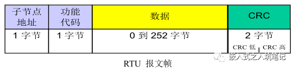
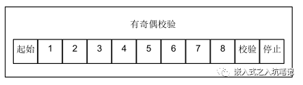
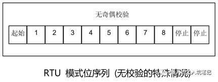
The maximum total length of Modbus RTU frames is 256 bytes. The format of each byte (11 bits) in RTU mode is:8-bit binary, each 8-bit byte in the message contains two 4-digit hexadecimal characters (0-9, A-F), and the bit stream per byte is:Starting position 18 data bits, first send the least significant bit1 bit as parity check1 stop positionEven parity is required, but other modes (odd parity, no parity) can also be used. To ensure maximum compatibility with other products, it is recommended to support the unverified mode. The default verification mode must be even verification. Note: Use 2 stop bits without verification requirements. When using RTU, each character or byte is sent in this order (from left to right):
Least Significant Bit (LSB)... Most Significant Bit (MSB)
5.1.1 Frame Communication in RTU Mode
Construct Modbus messages into frames with known start and end markers by the sending device. This allows the device to receive new frames at the beginning of a message and know when the message ends. Incomplete messages must be detectable and error flags must be set as a result. In RTU mode, message frames are distinguished by idle intervals of at least 3.5 characters in duration.
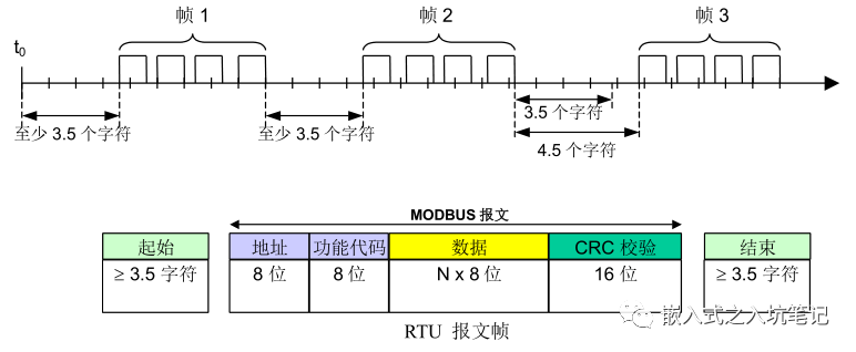
The entire message frame must be sent in a continuous stream of characters. If the idle interval between two characters is greater than 1.5 character times, the message frame is considered incomplete and should be discarded by the receiving node.
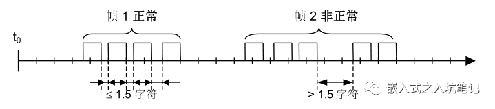
Attention: When receiving data in RTU mode, due to the time interval requirement of t1.5 and t3.5, it generally leads to increased CPU burden at high communication rates. Therefore, when the communication rate is equal to or lower than 19200 bps, these two timings must be strictly followed; For cases where the baud rate is greater than 19200 bps, two fixed values for timing should be used: the recommended inter character timeout (t1.5) is 750 µ s, and the inter frame timeout (t1.5) is 1.750ms. The following figure illustrates the description of the RTU transmission mode state diagram. The different angles of the 'master node' and 'child nodes' are represented in the same graph:
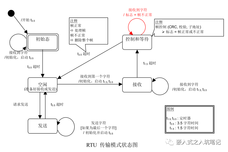
Some explanations of the state diagram above:
1) The transition from the "initial" state to the "idle" state requires a timed timeout of T3.5, which ensures inter frame delay
2) The 'idle' state is a normal state where there are no messages to be sent or received for processing.
3) In RTU mode, when there is no active transmission for a time interval of 3.5 characters, the communication link is considered to be in an "idle" state.
4) When the link is idle, any transmitted character detected on the link is recognized as the frame start. The link becomes' active 'state. Then, when the time interval during which no characters are transmitted on the chain reaches t3.5, it is recognized as the end of the frame.
5) After detecting the end of the frame, complete CRC calculation and verification. Then, analyze the address field to determine if the frame is being sent to this device, and if not, discard the frame. In order to reduce the receiving processing time, the address field can be analyzed as soon as it is received, without waiting until the end of the entire frame. In this way, CRC calculation only needs to be performed when the frame is addressed to that node (including broadcast frames).
5.1.2 CRC verification in RTU mode
In RTU mode, there is an error checking field based on the cyclic redundancy checking (CRC) algorithm that performs on all message contents. CRC domain checks the content of the entire message. This check is performed regardless of whether the message has parity or not. CRC contains a 16 bit value consisting of two 8-bit bytes. The CRC field is attached as the last field of the message after the message. After calculation, the low byte is appended first, followed by the high byte. The CRC high byte is the last sub section of the message sent. The CRC value attached to the message is calculated by the sending device. The receiving device recalculates the CRC value when receiving the message and compares the calculated result with the actual received CRC value. If two values are not equal, it is an error. The calculation of CRC starts by pre installing all 1s on a 16 bit register. Then perform subsequent calculations on the consecutive 8-bit segments in the message. Only 8 data bits in the character participate in the CRC generation operation, and the start bit, stop bit, and check bit do not participate in the CRC calculation. During the generation process of CRC, each 8-bit character is XORed with the value in the register. Then the result shifts (Shift) 1 bit towards the least significant bit (LSB) direction, while the most significant bit (MSB) position is charged to zero. Then extract and check the LSB: if LSB is 1, the value in the register is XORed with a fixed preset value; If LSB is 0, no XOR operation is performed. This process will be repeated until 8 shifts are executed. After completing the last (8th) shift and related operations, the next 8-bit byte is XORed with the current value of the register, and then repeated 8 times as described above. The final value of the register obtained after all sub nodes have been computed in all messages is the CRC.
5.2 ASCII transmission mode
When a Modbus serial link device is configured to communicate in ASCII mode, each 8-bit byte in the message is sent as two ASCII characters. This mode is generally used when the communication link or device cannot comply with the timing management of RTU mode. The frame format of ASCII is as follows:

For example, byte 0X5B will be encoded into two characters: 0x35 and 0x42 (ASCII encoding 0x35="5", 0x42="B").Note: Due to the requirement of two characters for a subsection, this mode is less efficient than RTU.
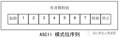
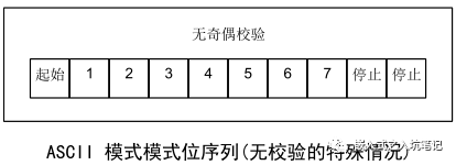
The format of each byte (10 bits) in ASCII mode is hexadecimal, ASCII characters 0-9, A-F.Starting position 17 data bits, first send the least significant bit1 bit as parity check1 stop positionEven parity is required, but other modes (odd parity, no parity) can also be used. To ensure maximum compatibility with other products, it is recommended to support the unverified mode. The default verification mode must be even verification. Note: Use 2 stop bits without verification requirements. How are characters transmitted serially: Each character or byte is sent in this order (from left to right):
Least Significant Bit (LSB)... Most Significant Bit (MSB)
5.2.1 ASCII message frames
In ASCII mode, messages use special characters to distinguish between frame start and frame end.A message must start with a 'colon' (:) (ASCII hexadecimal 3A) and end with a 'carriage return line break' (CR LF) pair (ASCII hexadecimal 0D and 0A).Note: The LF character can be changed through specific Modbus application commands (see Modbus Application Protocol Specification). For all domains, the allowed characters to be transmitted are hexadecimal 0-9, A-F (ASCII encoding). The 'colon' character on the continuous monitoring bus of the device. After receiving this character, each device decodes the subsequent characters until the end of the frame. The time interval between characters in the message can reach one second. If there is a larger interval, the receiving device considers that an error has occurred. Special note: Each character subsection needs to be encoded with two characters. Therefore, in order to ensure compatibility between ASCII mode and RTU mode at the Modbus application level, the maximum data length of the ASCII data field (2x252) is twice that of the RTU data field (252). Undoubtedly, the maximum size of Modbus ASCII frames is 513 characters. The requirements for ASCII message frames are summarized in the following state diagram. The different angles of the 'master node' and 'child nodes' are represented in the same graph:
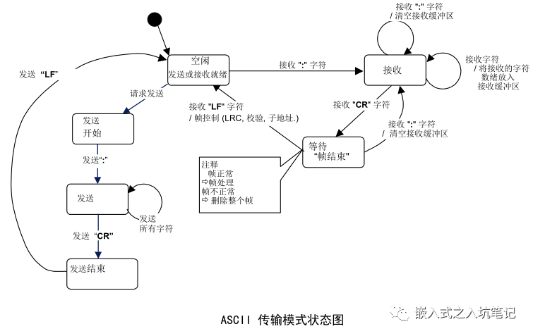
Some explanations for the state diagram above: 1) The "idle" state is a normal state where there are no messages to be sent or received for processing. 2) Each time the ":" character is received, it indicates the beginning of a new message. If the character is received during the reception of a message, the current message is considered incomplete and discarded. And a new receiving buffer is reallocated. 3) After detecting the end of the frame, complete LRC calculation and verification. Then, analyze the address field to determine if the frame is being sent to this device, and if not, discard the frame. In order to reduce the receiving processing time, the address field can be analyzed as soon as it is received, without waiting until the end of the entire frame.
5.2.2 LRC verification of ASCII
In ASCII mode, there is an error checking field based on the Longitudinal Redundancy Checking (LRC) algorithm that performs on all message contents. The LRC domain check does not include the entire message content of the starting "colon" and ending CRLF pairs. This check is performed regardless of whether the message has parity or not. The LRC field is a subsection that contains an 8-bit binary value. The LRC value is calculated by the sending device and then attached to the message. The receiving device recalculates the LRC value when receiving the message and compares the calculated result with the actual received LRC value. If two values are not equal, it is an error. The calculation of LRC involves adding up all consecutive 8-bit bytes in the message, ignoring any carry, and then finding their binary complement. Perform verification on the content of the entire ASCII message field, excluding the starting colon and ending CRLF pairs. In ASCII mode, the result of LRC is encoded into two bytes by ASCII and placed at the end of the ASCII mode message frame, before CRLF.
6. Modbus exception codes
The general process of MODBUS transaction processing:
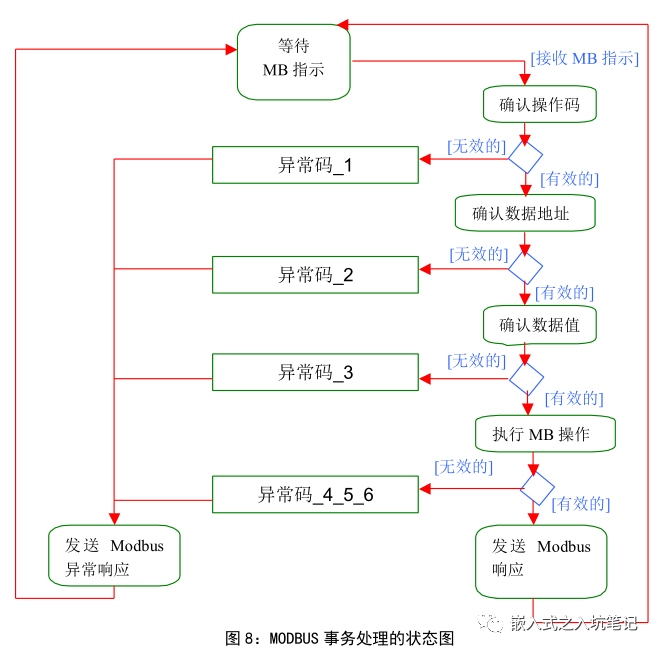
Once the server processes the request, establish a MODBUS response using an appropriate MODBUS server transaction. Based on the processing results, two types of responses can be established:
1) A correct MODBUS response: Response function code=Request function code
2) A MODBUS abnormal response
3) Used to provide clients with information related to errors discovered during the processing;
4) Response function code=Request function code+0x80;
5) Provide an exception code to indicate the cause of the error.
7. Modbus Function Code
7.1 Categories of Function Codes
At present, Modbus functions can be divided into three categories: public function codes, user-defined function codes, and reserved function codes.
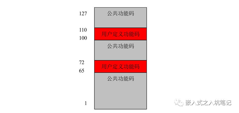
Public function code: It is a defined function code.
User defined function code: There are two function codes that can be defined by the user. The range is 65 to 72 and decimal 100 to 110.
Reserved function code: a function code that is used in special circumstances and is invalid for public use.
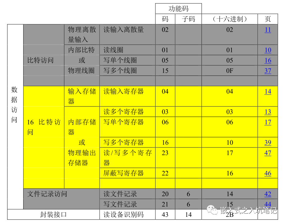
7.2. Public Function Code
The definition of common function codes in Modbus is as follows:
7.2.1 Coil operation function code (bit operation)
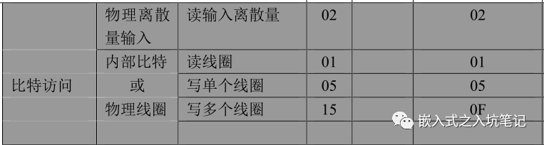
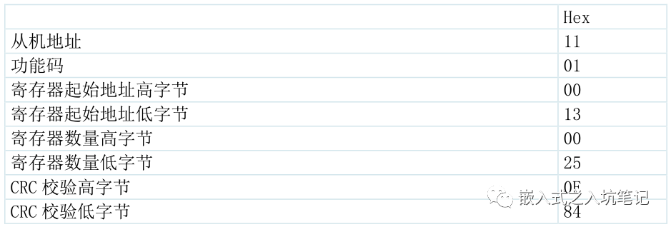
For example, I need to read the contents of the coil. The slave address is 11H, the starting address of the coil register is 0013H, and the ending address is 0037H. A total of 37 coil registers need to be queried, and the RTU frame sent by the host is as follows:
The data frames responded by the slave are as follows:
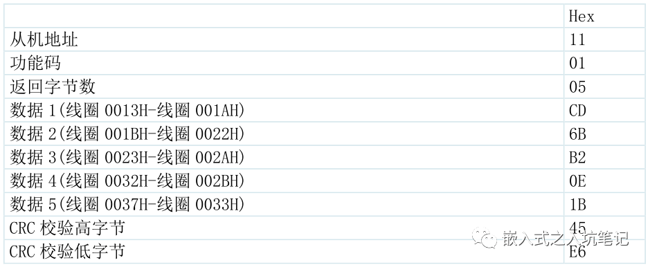
Analysis: The state from coil 0013H to coil 001AH is CDH, with a binary value of 11001101. The highest byte of this byte is coil 001AH, and the lowest byte is coil 0013H. Each coil state corresponds to each bit of the data content. 1 represents ON, 0 represents OFF. The states of coil 001AH to coil 0013H are:

7.2.2. Maintain register operation function codes
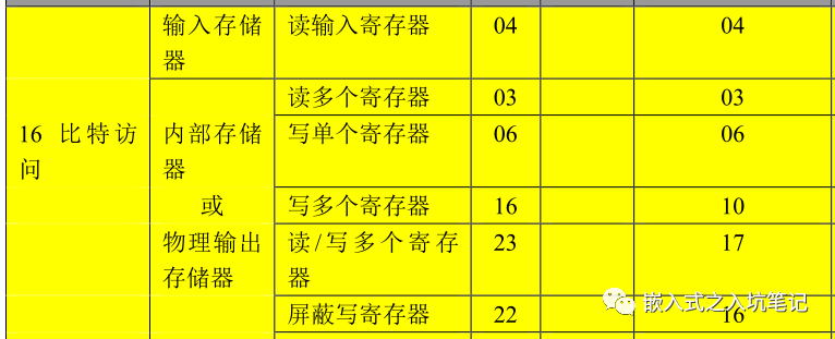
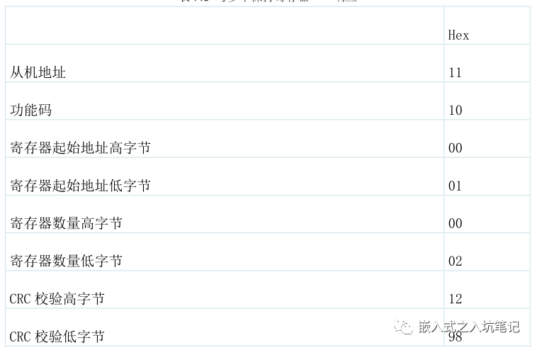
(1) Write multiple hold registers
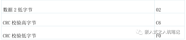
Write multiple hold registers using function code 10H. For example, the slave address is 11H. The actual address of the hold register is 0001H, and the end address of the register is 0002H. A total of 2 registers are accessed. Keep the contents of register 0001H as 000AH and register 0002H as 0102H.
The RTU frame data requested by the host is as follows:

The response returned by the slave is:
(2) Read and hold register
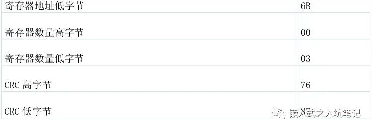
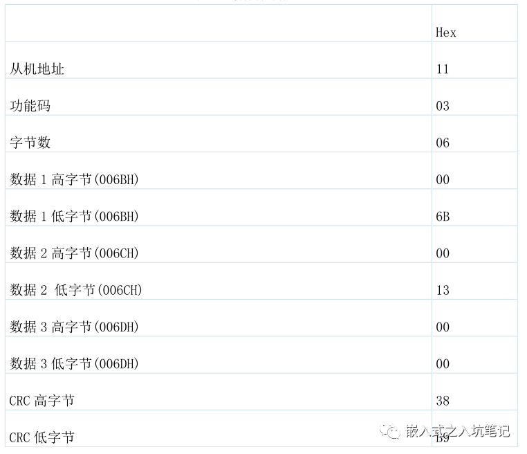
Read and hold registers using the 03H function code. For example, if the slave address is 11H, keep the starting address of the register as 006BH and the ending address as 006DH.
The RTU request frame sent by the host is as follows:

The response from the slave is as follows:


Leave a Reply