
Comparative Analysis of Modbus and Mainstream Industrial Protocols: A Comprehensive Showdown between PROFIBUS, EtherNet/IP, PROFINET, and CANopen
In the field of industrial automation, the choice of communication protocol directly affects the reliability, real-time performance, and maintenance cost of the system. Modbus, as an "old-fashioned" protocol born in 1979, is still operating in millions of industrial devices worldwide. However, with the advancement of Industry 4.0, protocols such as PROFIBUS, EtherNet/IP, PROFINET, and CANopen are emerging one after another. Engineers face a core question at the beginning of a project:Which protocol should they choose?
This article will conduct a comprehensive comparative analysis ofModbus and mainstream industrial protocols from multiple dimensions, including protocol architecture, physical layer, transmission mechanism, real-time performance, cost, and ecosystem,to help you make informed selection decisions in practical projects. The full text is about 8000 words, and it is recommended to bookmark and read later.
Core Keywords:Modbus vs PROFIBUS, Industrial Protocol Comparison, Modbus and EtherNet/IP, Industrial Communication Protocol Selection. For more Modbus technical articles, please visitmodbus.cn.
I. Classification of Industrial Protocols: Fieldbus vs Industrial Ethernet
Before conducting an in-depth comparison, we need to clarify the classification system of industrial communication protocols. Current industrial communication protocols are mainly divided into two camps:Traditional FieldbusAndIndustrial Ethernet.
1.1 Traditional Fieldbus
Fieldbus was born in the 1980s and 1990s, replacing traditional 4-20mA analog signals and point-to-point wiring. Its characteristics include:
- Utilizing dedicated physical layers (such as RS-485, MBP)
- Generally low speed (tens of Kbps to several Mbps)
- Simple topology (daisy chain, bus type)
- Representative protocols:Modbus RTU, PROFIBUS DP, CANopen, DeviceNet, CC-Link
1.2 Industrial Ethernet
Industrial Ethernet adds real-time and deterministic transmission capabilities to standard Ethernet (IEEE 802.3). Its characteristics include:
- Based on standard Ethernet hardware (RJ45, fiber optics)
- High speed (100Mbps to 1Gbps)
- Supports various topologies such as star, ring, and linear
- Seamlessly integrates with IT networks
- Representative protocols:Modbus TCP, PROFINET, EtherNet/IP, EtherCAT, POWERLINK
1.3 Unique position of Modbus
Modbus is the only protocol that spans both the fieldbus and industrial Ethernet camps:
- Modbus RTU/ASCII(RS-485/RS-232 physical layer) → fieldbus
- Modbus TCP(Ethernet physical layer) → industrial Ethernet
This cross-generation compatibility gives Modbus a unique ecological niche in protocol competition.
II. Comparison and Overview of Core Features of Various Protocols
The following table provides a horizontal comparison of mainstream industrial protocols from multiple dimensions, helping readers quickly establish a global understanding.
| Comparison Dimensions | Modbus RTU | Modbus TCP | PROFIBUS DP | EtherNet/IP | PROFINET | CANopen |
|---|---|---|---|---|---|---|
| Protocol Type | Fieldbus | Industrial Ethernet | Fieldbus | Industrial Ethernet | Industrial Ethernet | Fieldbus |
| Year of Birth | 1979 | 1999 | 1993 | 2001 | 2003 | 1995 |
| Main Promoting Organization | Modicon (Schneider) | Modbus-IDA | PI (PROFIBUS & PROFINET International) | ODVA | PI | CiA (CAN in Automation) |
| Degree of Openness | Fully open | Fully open | Open standard | Open standard | Open standard | Open standard |
| Physical layer | RS-485/RS-232 | Ethernet (IEEE 802.3) | RS-485 / MBP | Ethernet | Ethernet | CAN bus |
| Maximum rate | 115.2 Kbps | 100 Mbps / 1 Gbps | 12 Mbps | 100 Mbps / 1 Gbps | 100 Mbps / 1 Gbps | 1 Mbps |
| Maximum number of nodes | 247 | Theoretically unlimited | 126 | Theoretically unlimited | Theoretically unlimited | 127 |
| Maximum transmission distance | 1200m (RS-485) | 100m (copper cable) / several kilometers (fiber optic) | 1200m (RS-485, repeatable) | 100m (copper cable) / several kilometers (fiber optic) | 100m (copper cable) / several kilometers (fiber optic) | 40m @ 1Mbps |
| Transmission mode | Master-Slave (single master) | Client-Server | Master-Slave + Token Passing | Producer-Consumer | Provider-Consumer | Producer-Consumer |
| Real-Time Capability | Low | In the middle | In the middle | Medium-High | High (IRT up to 31.25μs) | In the middle |
| Data Model | Coil, Discrete Input, Hold Register, Input Register | Identical to Modbus RTU | Byte/Word Input/Output, Diagnostic Data | CIP Object Model | Slot/Sub-Slot Model | Object Dictionary |
| Typical applications | Instrument readings, simple IO control | SCADA, MES integration | PLC and distributed IO communication | Discrete manufacturing, packaging machinery | Motion control, high-speed production line | Vehicles, medical, embedded devices |
| Implementation complexity | Extremely low | Low | In the middle | Medium to high | High | In the middle |
| Hardware cost | Extremely low | Low | In the middle | In the middle | Medium and High | Low |
III. Comparison of OSI Model Layer Depths
The differences in industrial protocols are most clearly reflected in the OSI seven-layer model. The implementation strategies of different protocols for each layer determine their scope of application and performance bottlenecks.
| OSI Layers | Modbus RTU | Modbus TCP | PROFIBUS DP | EtherNet/IP | PROFINET RT | CANopen |
|---|---|---|---|---|---|---|
| Layer 7 - Application Layer | Modbus Application Protocol | Modbus Application Protocol | DP User Interface | CIP Application Object | PROFINET IO | CANopen Application Layer (CiA 301) |
| Layer 6 - Presentation Layer | — | — | — | — | — | — |
| Layer 5 - Session Layer | — | — | — | — | — | — |
| Layer 4 - Transport Layer | — | TCP (Port 502) | FDL Layer (Partially) | TCP/UDP | UDP/IP (Real-time Channel) | — |
| Layer 3 - Network Layer | — | IP | — | IP | IP | — |
| Layer 2 - Data Link Layer | Modbus Serial Link | Ethernet MAC | FDL (Fieldbus Data Link) | Ethernet MAC + CIP | Ethernet MAC + RT Bypass | CAN Data Link Layer |
| Layer 1 - Physical Layer | RS-485/RS-232 | 100BASE-TX | RS-485 / MBP | 100BASE-TX | 100BASE-TX | CAN Transceiver |
3.1 Simplified Philosophy of Modbus
Modbus (especially Modbus RTU) is a typicalthree-layer architecture(application layer + data link layer + physical layer), skipping the middle layers of the OSI model. This design brings extremely low protocol overhead - a typical Modbus RTU frame header is only 4 bytes (address + function code).
However, the simplified architecture also means that Modbus lacks routing capabilities (in RTU mode), built-in security mechanisms, and time synchronization functions. These need to be supplemented by upper-layer SCADA or gateway software in modern industrial scenarios.
3.2 Hybrid Architecture of PROFIBUS
PROFIBUS implements the FDL (Fieldbus Data Link) layer at the data link layer, supportinghybrid media access control of master-slave communication + token passing. When there are multiple master stations in the system, conflict-free communication between master stations is achieved through a token ring. This design strikes a balance between real-time performance and flexibility, but also increases the complexity of the protocol stack.
3.3 Three-Layer Overlay of Industrial Ethernet
EtherNet/IP and Modbus TCP run application layer protocols on top of the standard TCP/IP protocol stack. CIP (Common Industrial Protocol) is the core of EtherNet/IP, providing a complete object model (identification object, connection object, parameter object, etc.), with functionality far richer than Modbus's "four data table" model.
PROFINET goes one step further: it has two communication channels -standard channelusing TCP/IP (for configuration and diagnosis), andreal-time channelbypassing the TCP/IP protocol stack directly to access the Ethernet MAC layer, thereby reducing the cycle time to 31.25 microseconds (IRT mode).
IV. Comparison of Physical Layer and Topology
| Physical characteristics | Modbus RTU | PROFIBUS DP | CANopen | EtherNet/IP | PROFINET |
|---|---|---|---|---|---|
| Transmission medium | Twisted pair (RS-485) | Twisted pair / MBP | Twisted pair (CAN_H/CAN_L) | Twisted pair / Fiber optic | Twisted pair / Fiber optic |
| Interface | DB9 / Terminal | DB9 / M12 | DB9 / Terminal | RJ45 / M12 / SFP | RJ45 / M12 / SFP |
| Topology | Bus Type (Daisy Chain) | Bus Type (Supporting Repeater Expansion) | Bus Type | Star / Linear / Ring | Star / Linear / Ring / MRP Ring Network |
| Terminating Resistor | 120Ω Both Ends | Active Termination | 120Ω Both Ends | Not Required | No need for |
| isolation requirements | Recommend optoelectronic isolation | Recommend isolation | Recommend isolation | Transformer isolation (standard) | Transformer isolation (standard) |
| Anti-interference capability | Differential signal, medium | RS-485 differential | Differential signal, strong | Differential + transformer, strong | Differential + Transformer, Strong |
| Hot-swappable with Power | Not Supported | Limited Support | Supported | Supported | Supported |
V. Comparison of Addressing Methods and Data Models
5.1 Modbus Addressing Model
Modbus adopts a simple addressing model based onfunction codes + data addresses, defining four data zones:
| Data Area | Type | Address Range | Read/Write Permission | Typical Usage |
|---|---|---|---|---|
| Coil | Boolean (1 bit) | 00001-09999 | Read/Write | Digital Output, Relay |
| Discrete Input | Boolean (1 bit) | 10001-19999 | Read-Only | Digital input, switch |
| Holding Register | 16-bit word | 40001-49999 | Read/write | Analog quantity, parameter |
| Input Register | 16-bit word | 30001-39999 | Read-only | Analog input |
This model is extremely simple, but it also has significant limitations:It lacks data type semantics. Whether the value of a holding register is an unsigned integer, signed integer, or floating-point number is completely agreed upon by both communication parties in advance. 32-bit data types require the occupation of two consecutive registers, and the endianness order also needs to be agreed upon outside the protocol.
5.2 CANopen's Object Dictionary
CANopen defines a standardized data access model through theObject Dictionary (OD). Each object has a 16-bit index and an 8-bit sub-index, with type information (INT8, UINT16, FLOAT32, STRING, etc.) built into the dictionary entry. This design eliminates the "type convention" issue commonly found in Modbus.
5.3 EtherNet/IP's CIP Object Model
CIP defines a complete set of object models, including:
- Required objects:Identity, Message Router, Connection Manager
- Application objects:Motor data object, position sensor object, discrete IO object
- Vendor-specific objects:Customized extensions by device manufacturers
CIP also supports explicit messages (request-response mode, used for configuration) and implicit messages (periodic IO data, used for real-time control). This dual-mode design is more adaptable to modern automation requirements than Modbus's single request-response mechanism.
VI. Comparison of Real-Time Performance
Real-time performance is one of the most critical indicators in the selection of industrial protocols. Different protocols can vary by several orders of magnitude in terms of cycle time and determinism (jitter).
| Protocol | Typical cycle time | Minimum cycle time | Determinism | Applicable scenarios |
|---|---|---|---|---|
| Modbus RTU | 50-500 ms | ~10 ms | Low | Instrument readings, slow IO |
| Modbus TCP | 10-100 ms | ~2 ms | In the middle | SCADA, MES Integration |
| PROFIBUS DP | 1-10 ms | ~0.5 ms | Medium-High | PLC and Distributed IO |
| CANopen | 1-20 ms | ~0.5 ms | High | Embedded Control |
| EtherNet/IP (CIP Sync) | 1-20 ms | ~0.5 ms | Medium-High | Discrete Manufacturing |
| PROFINET RT | 1-10 ms | ~0.25 ms | High | Motion Control |
| PROFINET IRT | 0.25-1 ms | 31.25 μs | Extremely High | High-Precision Motion Control |
| EtherCAT | 0.05-1 ms | 12.5 μs | Extremely High | Ultra-High-Speed Motion Control |
The fundamental reason for the low real-time performance of Modbus:
- Master-Slave Polling Mechanism:Only one transaction can be processed at a time, and all slaves must wait for polling
- Physical Layer Limitations:Baud rate bottleneck of RS-485 (maximum 115.2 Kbps)
- No Interrupt/Event Mechanism:Slaves cannot proactively report status changes
VII. Cost and Ecosystem Comparison
| Cost Dimension | Modbus | PROFIBUS | CANopen | EtherNet/IP | PROFINET |
|---|---|---|---|---|---|
| Protocol Licensing Fee | Free | Requires Joining the PI Organization | Requires joining the CiA organization | Requires joining the ODVA organization | Requires joining the PI organization |
| Chip/module cost | Extremely low (MCU+485 transceiver) | Medium (dedicated ASIC) | Low (MCU+CAN controller) | Medium (Ethernet+protocol stack) | Medium-high (dedicated chip or protocol stack) |
| Development difficulty | Extremely low | In the middle | In the middle | Medium-high | High |
| Debugging tool cost | Free/low cost | Medium (ProfiTrace, etc.) | In the middle | In the middle | High |
| Training cost | Low | In the middle | In the middle | Medium-high | high |
| Ecosystem | Extremely extensive | Mainly in Europe | Mainly embedded | Mainly in North America | Europe/global |
One of the biggest advantages of Modbus isIt has almost zero threshold. A single-chip microcomputer plus a few cents worth of RS-485 transceiver can achieve the slave function. There is no protocol stack licensing fee, no certification requirement, and the protocol specification is completely open. This is why Modbus is adopted by thousands of device manufacturers worldwide.
VIII. In-depth Analysis of the Advantages and Disadvantages of Modbus
8.1 Core Advantages of Modbus
- Extreme Simplicity:The protocol frame structure is clear, and the function codes are limited (1-255, with less than 10 commonly used), allowing developers to master and implement basic communication within a day.
- Fully Open:No patent barriers, no licensing fees, no mandatory certification, and standard documentation is freely available.
- Unparalleled Ecosystem:Almost all PLCs (Siemens, Rockwell, Mitsubishi, Omron), HMI, SCADA software, frequency converters, and sensors natively support Modbus.
- Cross-Generation Compatibility:Supported versions include RTU serial and TCP Ethernet, allowing for easy bridging between old and new systems through a simple gateway.
- Extremely low hardware cost:RS-485 transceivers are inexpensive, and Ethernet versions can utilize standard network cards.
- Rich open-source code:High-quality open-source implementations such as libmodbus, FreeMODBUS, and pymodbus greatly reduce integration difficulty.
8.2 Core disadvantages of Modbus
- Insufficient real-time performance:The polling mechanism cannot meet the requirements of high-speed motion control (<1ms cycle).
- No data semantics:Data types and units need to be manually agreed upon, which is prone to errors.
- No security mechanism:No encryption and authentication, not suitable for scenarios directly exposed on the public network.
- Single master limitation:Standard Modbus RTU can only have one master station, and multiple master stations require special handling.
- Limited addressing space:Traditional addressing methods are limited to 65535 register addresses.
- No time synchronization:Does not support distributed clock synchronization, and data time stamping needs to be implemented at the application layer.
- No plug-and-play:There is no device discovery and automatic configuration mechanism, and each device requires manual configuration of communication parameters.
8.5, PROFIBUS vs PROFINET: Continuation and Evolution of Brother Protocols
Many engineers easily confuse PROFIBUS and PROFINET, thinking they only differ in the physical layer. In fact, the differences between the two are much greater than imagined.
Design Philosophy of PROFIBUS
PROFIBUS (Process Field Bus) was born in 1989 and was initially funded by the German Federal Ministry of Education and Research. It aims to provide a unified fieldbus standard for manufacturing and process automation. PROFIBUS has two main variants: PROFIBUS DP (Decentralized Peripherals, for high-speed discrete IO) and PROFIBUS PA (Process Automation, for intrinsically safe and explosion-proof environments). PROFIBUS DP is based on the RS-485 physical layer and supports data rates up to 12 Mbps. Its core innovation lies inhybrid media access controlMaster stations communicate without collision through a token ring, while master-slave stations exchange data through polling. This design allows multiple master stations (such as multiple PLCs and engineering stations) to share the same bus without interfering with each other.
Revolutionary Changes in PROFINET
PROFINET (Process Field Network) is a comprehensive upgrade of PROFIBUS in the Ethernet era. It is no longer just "PROFIBUS running on Ethernet", but has redesigned its communication architecture. PROFINET offers three performance levels:NRT (Non-Real-Time)uses standard TCP/IP for configuration and diagnostics, with a cycle time of approximately 100ms;RT (Real-Time)bypasses TCP/IP and directly accesses the MAC layer, with a cycle time of 1-10ms;IRT (Isochronous Real-Time)achieves deterministic communication with a 31.25μs cycle time through hardware time slot scheduling. IRT mode requires dedicated switch support, but provides one of the highest time determinacies in industrial communication.
The transition from PROFIBUS to PROFINET is an industry trend, but there are still millions of nodes running on PROFIBUS globally. If you are planning a new project, prioritize PROFINET; if it is an extension of an existing PROFIBUS system, a hybrid architecture of PROFINET backbone and PROFIBUS subnet can be achieved through gateways such as IE/PB Link. For more technical details, please refer to the in-depth protocol analysis article onmodbus.cn.
IX. Hybrid Protocol Architecture Design: When to Use Modbus and When to Use Other Protocols?
In practical projects, choices are often not binary. An excellent system architecture willutilize multiple protocolsin the same factory, leveraging the strengths of each.
9.1 Scenarios Recommending the Use of Modbus
- Smart Instrumentation and Sensor Readings:Low-rate devices such as power meters, flowmeters, and temperature transmitters. The transmitter is connected to the controller via Modbus RTU, and readings can be taken once per second.
- SCADA System Integration:Reading production data from PLCs to the host computer via Modbus TCP for trend analysis and report generation.
- Building Automation:Scenarios with low real-time requirements such as HVAC and lighting control.
- Device-to-Gateway Connection:Low-level sensors → Modbus RTU → protocol conversion gateway → PROFINET/EtherNet/IP upper-layer network.
- Cost-sensitive projects:For small and medium-sized projects with limited budgets, the cost advantage of Modbus devices is very obvious.
- Renovation of old systems:For factories that already have a large number of Modbus RTU devices, it is recommended to retain the underlying bus while upgrading the upper-layer network.
9.2 Scenarios where PROFINET is recommended
- Motion control:Servo drives, multi-axis synchronization, and other applications require microsecond-level synchronization accuracy.
- High-speed production lines:Packaging machinery, printing machinery, and other applications require fast IO exchange.
- Safety-related:PROFIsafe provides certified safe communication (SIL 3).
- Siemens ecosystem:The integration of TIA Portal + S7 PLC + PROFINET is the highest.
9.3 Scenarios Recommending the Use of EtherNet/IP
- North American Market Projects:The Preferred Protocol in the Rockwell Allen-Bradley Ecosystem.
- Discrete Manufacturing:Material Handling, Sorting Systems, etc. Require Rich IO Device Support.
- CIP Object Model Requirements:Requires Standardized Device Descriptions and Parameter Configurations.
9.4 Scenarios Recommending the Use of CANopen
- Embedded Systems:A Low-Power, Low-Cost, Small Controller Network.
- Mobile Machinery:Distributed control on construction machinery and agricultural machinery.
- Medical equipment:The reliability and real-time performance of CAN bus are suitable for medical applications.
X. Typical hybrid architecture topology
Below is a typical hybrid protocol architecture of a factory:
                    ┌──────────────────────────────┐
                    │         MES / SCADA           │
                    │    (Modbus TCP / OPC UA)      │
                    └──────────────┬───────────────┘
                                   │ Ethernet
                    ┌──────────────┴───────────────┐
                    │       工业以太网交换机         │
                    └──┬────────┬────────┬────────┬┘
                       │        │        │        │
              ┌────────▼──┐ ┌──▼────┐ ┌─▼──────┐ ┌▼─────────┐
              │  Siemens  │ │Rockwell│ │ 网关1  │ │ 网关2    │
              │ S7-1500   │ │CLX  │  │Profinet│ │EtherNet/ │
              │ (PROFINET)│ │(EIP) │  │→Modbus │ │IP→Modbus │
              └───┬───────┘ └──┬───┘  └───┬────┘ └──┬───────┘
                  │            │          │         │
          ┌───────┴───────┐    │   ┌──────▼─────┐   │
          │  PROFINET IO  │    │   │  Modbus RTU │   │
          │  (伺服/远程IO) │    │   │  RS-485总线 │   │
          └───────────────┘    │   └──┬──┬──┬───┘   │
                               │      │  │  │       │
                    ┌──────────▼┐  ┌──▼──▼──▼──┐    │
                    │EtherNet/IP│  │电表│温传│流计│   │
                    │(变频器/IO)│  │ 1  │ 2  │ 3  │   │
                    └───────────┘  └────────────┘    │
                                                     │
                                        ┌────────────▼┐
                                        │  Modbus RTU │
                                        │  (旧有设备)  │
                                        └─────────────┘
The core idea of this architecture is:
- The backbone network uses industrial Ethernet protocol(PROFINET or EtherNet/IP) to ensure high-speed real-time communication
- The field device layer uses Modbus RTU, which is accessed to the upper layer through a protocol conversion gateway
- The SCADA/MES layer uses Modbus TCP or OPC UAto achieve cross-platform data aggregation
11. Protocol Conversion Gateway Technology
The protocol conversion gateway is a key component of the hybrid architecture, responsible for data mapping and forwarding between different protocols.
11.1 Common Gateway Types
| Gateway Types | Typical Products | Application Scenarios |
|---|---|---|
| Modbus RTU → Modbus TCP | MOXA MB3170, Anybus Communicator | Connecting Serial Devices to Ethernet |
| Modbus RTU → PROFINET | HMS Anybus X-gateway | Integrating Modbus Devices into Siemens Systems |
| Modbus RTU → EtherNet/IP | ProSoft PLX31 | Integrating Modbus devices into Allen-Bradley systems |
| Modbus RTU → CANopen | HMS Anybus Communicator CAN | Integrating Modbus devices into CAN networks |
| Modbus TCP → MQTT/OPC UA | Self-built Edge Gateway (Node-RED) | Integrating Modbus data into the cloud |
11.2 Considerations for self-built gateways
- Mapping table design:The mapping relationship from the source address (register/coil) to the destination address (slot/sub-slot, object dictionary index) must be clearly defined.
- Data refresh cycle:The polling frequency on the Modbus side determines the overall refresh rate and requires a balance between speed and network load.
- Exception handling:Strategy for when a Modbus device goes offline (maintain the last value? Set to zero? Alarm?).
- Byte order conversion:32-bit values may have different byte order in different protocols.
- Protocol limitation adaptation:Modbus can read up to 125 registers at a time (RTU), requiring proper combination of data groups.
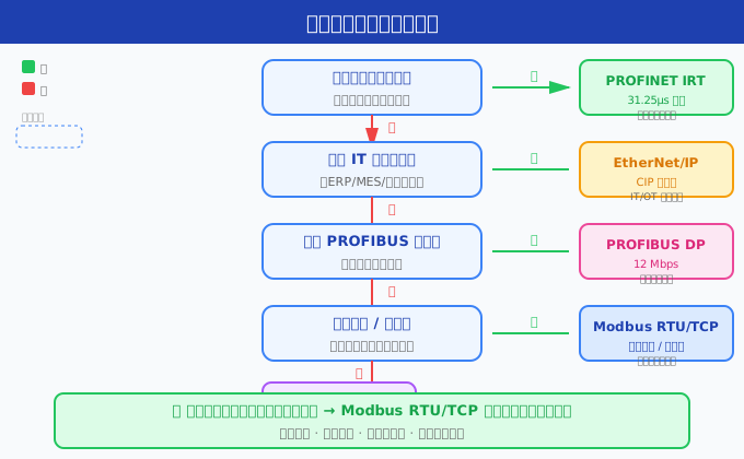
Twelve, Industrial Protocol Selection Decision Tree
Below is a practical protocol selection decision flowchart to help you quickly determine the most suitable protocol.
开始
 │
 ├─ 需要亚毫秒级实时控制?
 │   ├─ 是 → 需要多轴同步?
 │   │        ├─ 是 → PROFINET IRT / EtherCAT
 │   │        └─ 否 → PROFINET RT / EtherCAT
 │   └─ 否 ↓
 │
 ├─ 需要与 Rockwell (Allen-Bradley) PLC 集成?
 │   ├─ 是 → EtherNet/IP
 │   └─ 否 ↓
 │
 ├─ 需要与 Siemens PLC 集成?
 │   ├─ 是 → PROFINET (首选) / PROFIBUS
 │   └─ 否 ↓
 │
 ├─ 嵌入式/低功耗/低成本?
 │   ├─ 是 → CANopen / Modbus RTU
 │   └─ 否 ↓
 │
 ├─ 需要传输复杂数据类型和语义?
 │   ├─ 是 → EtherNet/IP (CIP) / CANopen
 │   └─ 否 ↓
 │
 ├─ 需要即插即用和设备自动发现?
 │   ├─ 是 → PROFINET / EtherNet/IP
 │   └─ 否 ↓
 │
 ├─ 预算极低 / 需要最低开发门槛?
 │   ├─ 是 → Modbus RTU / Modbus TCP
 │   └─ 否 ↓
 │
 ├─ 已有大量 Modbus 设备 / 仪表读取?
 │   ├─ 是 → Modbus RTU/TCP + 网关桥接
 │   └─ 否 ↓
 │
 └─ SCADA/MES/IT 集成优先?
     └─ 是 → Modbus TCP / OPC UA
Twelve and a half, Practical Case: The Evolution from Single Protocol to Hybrid Architecture
The following presents three real-world project scenarios to demonstrate how to make protocol choices in practice.
Case One: Small Wastewater Treatment Plant
Requirement:A set of PLC controls 30 electricity meters, 20 flowmeters, 10 valves, and 5 frequency converters. The system needs to upload data to the central SCADA system.
Selection analysis:Electricity meters and flowmeters usually come with Modbus RTU interfaces, and a reading cycle of 1-2 seconds is sufficient. Valve control does not require microsecond-level response. Frequency converters require a slightly faster response, but the 12Mbps rate of PROFIBUS is sufficient to complete parameter reading and writing for a single frequency converter within 10ms. Comprehensive consideration:
- Field instrument layer:Modbus RTU serial bus (RS-485), with 4 buses to avoid too many nodes on a single bus
- Controller layer:Siemens S7-1200 PLC, with built-in RS-485 communication module, reads all Modbus instruments through polling
- SCADA layer:Modbus TCP, PLC Ethernet port connects to the host computer WinCC through a switch
Key decision:Why not switch to PROFINET? Because if all 50 instruments and valves on site were replaced with PROFINET-interface devices, the cost would increase by at least three times, while Modbus RTU fully meets the response time requirements. This case illustrates that "good enough is good enough" is the iron law of industrial selection.
Case 2: High-Speed Packaging Line Renovation
Requirements:A production line capable of packaging 600 products per minute, involving synchronous motion control of 8 servo axes, visual inspection triggering, and a rejecting device. The synchronization error between servo axes is required to be less than 1 microsecond.
Selection Analysis:Such high-precision synchronous control is a forbidden area for Modbus. Both the 31.25μs cycle time of PROFINET IRT and the Distributed Clock (DC) mechanism of EtherCAT are suitable options. Final Selection:
- Controller Layer:Siemens S7-1500T Motion Controller + PROFINET IRT
- Servo Drive:SINAMICS S210, achieving isochronous synchronization through PROFINET IRT
- Auxiliary Sensors (Temperature, Pressure):Accessed through ET200SP Remote IO + PROFINET RT (non-critical, no IRT required)
- Interface with MES System:Modbus TCP (via OPC UA gateway) for uploading production count and quality data
Key Insights:Even in high-performance systems, Modbus still plays a supporting role in "information upload". PROFINET IRT is used for high-speed real-time control, while Modbus TCP is used for low-speed information aggregation, each performing its own function.
Case Study 3: Digital Upgrade of an Old Factory
Scenario:A chemical plant that has been operating for 15 years has over 200 Modbus RTU instruments at the bottom layer and 50 valve positioners supporting PROFIBUS DP. Management requires remote monitoring and data analysis.
Challenges Faced:
- The cost of equipment replacement is too high (the cost of replacing 200 instruments far exceeds the budget)
- A unified data interface is needed for use by the upper analysis platform
- The factory's network environment is complex, with aging RS-485 lines and newly deployed fiber optic ring networks
Solution - Three-Layer Hybrid Architecture:
- L1 Field Device Layer (not replaced):Modbus RTU instruments (via RS-485) and PROFIBUS DP valve positioners remain unchanged
- L2 aggregation gateway layer (new):Deploy HMS Anybus X-gateways in each workshop to uniformly convert Modbus RTU and PROFIBUS DP to Modbus TCP
- L3 data platform layer:Connect the workshop gateways via a fiber optic ring network, aggregate to the central data server through Modbus TCP, and then convert to MQTT for cloud integration via Node-RED
Project outcomes:Zero equipment replacement, production downtime controlled within 48 hours, and successful data collection across the entire factory. This case fully demonstrates the irreplaceability of Modbus in the renovation of old systems - not because it is the most advanced, but because it is the most compatible.
XIII. Summary of selection recommendations
| Application scenarios | Preferred protocol | Alternative protocol | Reasons |
|---|---|---|---|
| Smart instrument data acquisition | Modbus RTU | Modbus TCP | Lowest cost and widest device ecosystem |
| SCADA system integration | Modbus TCP | OPC UA | Ethernet access, IT-friendly |
| High-speed discrete manufacturing | EtherNet/IP | PROFINET | CIP object model, complete data semantics |
| Motion control (servo) | PROFINET IRT | EtherCAT | Microsecond-level synchronization, isochronous mode |
| Embedded/low-power | CANopen | Modbus RTU | CAN hardware is widely used, with good real-time performance |
| Building automation | Modbus RTU/TCP | BACnet | Wide range of device types, cost-sensitive |
| Siemens Ecosystem Integration | PROFINET | PROFIBUS | Native Support, High Engineering Efficiency |
| Rockwell Ecosystem Integration | EtherNet/IP | DeviceNet | Native Support, Complete Functionality |
| Mobile Machinery/Vehicles | CANopen | SAE J1939 | Strong Anti-interference, High Reliability |
| Data Clouding | Modbus TCP→MQTT | OPC UA | Simple Implementation of Edge Gateway |
XIV. FAQ: Common Issues of Industrial Protocols
Q1: Can Modbus and PROFIBUS be used simultaneously?
A: Of course. Modbus RTU devices can be seamlessly integrated into PROFIBUS or PROFINET networks through protocol conversion gateways such as the HMS Anybus X-gateway. This is very common in the retrofitting of old factories, where the underlying Modbus instruments are retained while the upper layer is upgraded to a PROFINET control system.
Q2: Can Modbus TCP and EtherNet/IP run on the same Ethernet cable?
A: Yes, they can. They share the Ethernet physical layer, and different protocols are distinguished by different TCP/UDP port numbers (Modbus TCP defaults to 502, while EtherNet/IP uses 44818, etc.). It is feasible to run multiple industrial Ethernet protocols simultaneously on the same switch, but attention should be paid to network load and VLAN isolation.
Q3: Why hasn't Modbus been eliminated in the era of Industry 4.0?
A: There are three core reasons: (1) simplicity - development costs are extremely low; (2) ecosystem - tens of thousands of Modbus devices are still being sold; (3) cost - RS-485 chips are cheap and reliable. For 90% of non-real-time applications, Modbus' performance is more than sufficient. Just like TCP/IP, "sufficient" is the strongest vitality.
Q4: Which one should I choose between PROFINET and EtherNet/IP?
A: It mainly depends on your PLC brand. If you are in the Siemens ecosystem, choose PROFINET; if you are in the Rockwell (Allen-Bradley) ecosystem, choose EtherNet/IP. Both are comparable in performance, but PROFINET has advantages in high-speed motion control (IRT). If your system is a mix of brands, OPC UA, as a unified communication standard, is also worth considering.
Q5: How long does it take to learn Modbus development?
A: If you have basic knowledge of serial communication, you can master Modbus RTU development within a week. It is recommended to read relevant tutorials onmodbus.cnor use open-source libraries such as libmodbus and pymodbus to get started quickly.
Q6: Will Modbus devices conflict with each other?
A: In a Modbus RTU network, each slave station must have a unique address (1-247). If two devices have the same address, it will lead to communication conflicts and data corruption. Modbus TCP, on the other hand, uses IP addresses to identify devices, eliminating the need for additional station addresses.
Q7: What is the difference in response speed between CANopen and Modbus?
A: The typical cycle time for CANopen is between 1-20ms, while Modbus RTU typically ranges from 50-500ms. However, this is not determined by the protocol itself, but also depends on the baud rate, number of nodes, and data volume. At the same baud rate (such as 1Mbps CAN vs 115.2Kbps Modbus), CAN indeed has superior real-time performance and determinism compared to RS-485.
15. Summary
There is no perfect protocol, only the right protocol. The simplicity and low cost of Modbus make it the "Swiss Army Knife" of industrial communication, irreplaceable in scenarios such as instrument reading and SCADA integration. Protocols such as PROFINET, EtherNet/IP, and CANopen each have their strengths, filling Modbus's gaps in high-speed control, data semantics, and secure communication.
Core Principles for Selection:
- Define Requirements Before Choosing a Protocol- Clarify real-time performance, data volume, and reliability requirements
- Consider Ecosystem and Brand- PLC brand often determines protocol selection
- Do Not Exclude Hybrid Architecture- Using different protocols for different layers is the best practice
- Cost is also Performance——The low cost of Modbus itself is a kind of competitiveness.
For more in-depth articles on Modbus technology, please visitmodbus.cn. Recommended reading:Core Differences between Modbus RTU and Modbus TCP, Complete Guide to Modbus Function Codes, Modbus CRC/LRC Checking Principle and Programming Implementation.
This article is originally created by the modbus.cn technical team. Please indicate the source when reprinting. Updated date: June 2026.


Leave a Reply