
Best Practices for Modbus TCP/IP Network Deployment: A Complete Architecture Guide from Stand-Alone Debugging to Industrial Cloud Platforms
Keywords:Modbus TCP Deployment, Modbus TCP Network Architecture, Industrial Ethernet, Modbus Gateway Configuration, Modbus TCP Optimization
When factories transition from "stand-alone automation" to "networked production", Modbus TCP is the preferred protocol for connecting field devices to upper-level information systems. However, simply replacing RS-485 with network cables does not automatically guarantee stable and reliable communication - network topology design, IP planning, firewall configuration, multi-master concurrency, timeout and retry strategies, any negligence in any of these links can lead to communication interruptions or even production accidents.
This article systematically outlines all the key aspects to consider during the Modbus TCP deployment process from the dual perspectives of network engineers and automation engineers, and provides directly implementable configuration schemes.
1. Network Topology Design
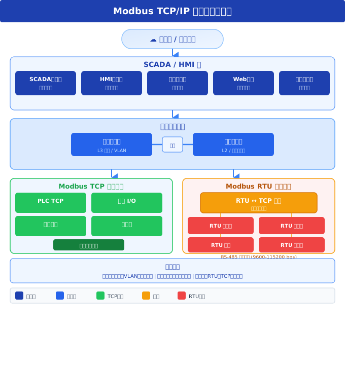
1.1 Recommended Hierarchical Network Architecture
A typical Modbus TCP industrial network should be divided into three levels:
┌──────────────────────────────────────────┐
│  Level 3 - 企业层                        │
│  ┌────────┐ ┌────────┐ ┌──────────────┐ │
│  │  MES   │ │  ERP   │ │ 远程监控中心  │ │
│  └───┬────┘ └───┬────┘ └──────┬───────┘ │
├──────┼─────────┼──────────────┼─────────┤
│  Level 2 - 控制层              │         │
│  ┌───┴─────────┴──────────────┴───────┐ │
│  │         SCADA / OPC UA 服务器       │ │
│  └──────────────────┬─────────────────┘ │
├─────────────────────┼───────────────────┤
│  Level 1 - 现场层    │                   │
│  ┌──────┐ ┌──────┐ ┌┴─────┐ ┌──────┐  │
│  │PLC #1│ │PLC #2│ │ 网关 │ │HMI   │  │
│  └──┬───┘ └──┬───┘ └──┬───┘ └──────┘  │
│     │RS-485  │RS-485  │RS-485          │
│  ┌──┴──┐  ┌──┴──┐  ┌──┴──┐            │
│  │从站 │  │从站 │  │从站 │            │
│  └─────┘  └─────┘  └─────┘            │
└──────────────────────────────────────────┘- Field Level (Level 1):Actual Modbus devices, which may be native TCP devices or RTU devices accessed through a gateway
- Control Level (Level 2):SCADA systems and OPC UA servers are responsible for data aggregation and centralized monitoring.
- Enterprise layer (Level 3):MES, ERP, cloud platforms, etc., utilize aggregated data obtained from the control layer.
Key principles:The enterprise layer should not directly access field-level devices. The reason for this design is that the network environment and security policies of the enterprise layer are completely different from those of the industrial field; direct access can bring unexpected communication loads to field devices; and security boundaries are more difficult to manage.
1.2 Selection of Industrial Switches
The industrial field environment is vastly different from the office environment, and choosing the right switch is the first line of defense for network reliability:
| Parameters | Recommended Requirements |
|---|---|
| Operating Temperature | -40°C ~ +75°C (Industrial Wide Temperature) |
| Protection Level | IP40 (inside the cabinet) / IP67 (on-site) |
| Redundant power supply | Dual DC 24V input |
| Ring protocol | Supports RSTP/ERPS (<50ms self-healing) |
| Management functions | VLAN, QoS, port mirroring (for packet capture debugging) |
| Recommended brands | MOXA, Hirschmann, Siemens Scalance |
II. IP address planning
2.1 Recommended address scheme
When planning IP addresses for industrial networks, the principle of "immediately recognizing the device at a glance" should be followed:
| Device Type | IP Range | Example |
|---|---|---|
| PLC | 192.168.1.10 ~ .29 | 192.168.1.11 = PLC #1 |
| HMI/Touch Screen | 192.168.1.30 ~ .49 | 192.168.1.31 = HMI #1 |
| Modbus Gateway | 192.168.1.50 ~ .69 | 192.168.1.51 = Gateway #1 |
| Frequency Converter/Servo | 192.168.1.70 ~ .89 | 192.168.1.71 = Inverter #1 |
| SCADA Server | 192.168.1.100 ~ .119 | 192.168.1.100 = SCADA Master Station |
| Switch/Management | 192.168.1.240 ~ .254 | 192.168.1.254 = Core Switch |
Core Principle:
- Use a subnet mask of /24 (255.255.255.0), which is sufficient to accommodate 254 devices
- Reserve address ranges for each device type, even if only a portion is currently in use
- Do not use DHCP in the industrial network segment - all devices use static IPs
- Establish an IP address ledger, including device name, location, MAC address, and firmware version.
III. VLAN Division and Security Isolation
3.1 Recommended VLAN Planning
| VLAN ID | Name | Purpose | Security Level |
|---|---|---|---|
| 10 | IO_Network | PLC, frequency converter, and other real-time control devices | High (Internet access prohibited) |
| 20 | SCADA_Network | SCADA, HMI, OPC UA servers | In the middle |
| 30 | Gateway_Network | Modbus TCP/RTU Gateway | High (Internet Access Prohibited) |
| 40 | Engineering | Engineer Station, Programming and Debugging Equipment | high |
| 100 | Enterprise | Interface with Factory IT Network | Medium (Firewall Required) |
3.2 Firewall Rule Configuration (Example with iptables)
# 允许 SCADA 网络访问 IO 网络的 Modbus TCP(端口 502)
iptables -A FORWARD -s 192.168.20.0/24 -d 192.168.10.0/24
  -p tcp --dport 502 -j ACCEPT

# 允许工程师站访问所有工业网络
iptables -A FORWARD -s 192.168.40.0/24 -d 192.168.0.0/16 -j ACCEPT

# 禁止企业网络直接访问 IO 网络
iptables -A FORWARD -s 192.168.100.0/24 -d 192.168.10.0/24 -j DROP

# 禁止从外部互联网访问工业网络
iptables -A FORWARD -i eth0 -d 192.168.0.0/16 -j DROP
IV. Multi-Master Communication Architecture
One significant advantage of Modbus TCP is its support for multiple masters to access the same slave device simultaneously. However, this does not imply unlimited connections—careful design of concurrency strategies is required.
4.1 Connection Limit
Typical Concurrent Connections Supported by a Modbus TCP Slave Device:
| Device Type | Typical Maximum Connections |
|---|---|
| Low-end PLC (such as Siemens S7-1200) | 4 ~ 8 |
| Mid-range PLC (such as S7-1500) | 16 ~ 32 |
| Modbus gateway | 8 ~ 32 (depending on the model) |
| PC-based Modbus Server | 100+ (limited by the operating system) |
Key reminder:Before connecting multiple master stations, be sure to consult the device manual to confirm the maximum connection count. Connection requests exceeding the limit will result in the device refusing service.
4.2 Socket reuse strategy
For scenarios requiring high-frequency polling, it is recommended to use Socket connection pool (persistent connection) rather than establishing a new connection for each request:
# Python 示例:使用连接池的 Modbus TCP 客户端
import socket
class ModbusTCPPool:
    def __init__(self, host, port=502, pool_size=3):
        self.host = host
        self.port = port
        self.pool = []
        for _ in range(pool_size):
            sock = socket.socket(socket.AF_INET, socket.SOCK_STREAM)
            sock.settimeout(5.0)
            sock.connect((host, port))
            self.pool.append(sock)

    def send_request(self, pdu):
        """从连接池取出 socket,发送请求"""
        sock = self.pool.pop(0)
        try:
            sock.sendall(pdu)
            response = sock.recv(1024)
            return response
        finally:
            self.pool.append(sock)  # 归还到连接池
V. Performance Optimization Strategies
5.1 TCP_NODELAY Option
The Nagle algorithm, enabled by default in TCP, attempts to combine small packets before sending them, aiming to reduce network load. However, for small packet communication in a request-response mode like Modbus TCP, the Nagle algorithm actually increases latency.
// C 语言:禁用 Nagle 算法
int flag = 1;
setsockopt(sock, IPPROTO_TCP, TCP_NODELAY, &flag, sizeof(flag));

// Python:
sock.setsockopt(socket.IPPROTO_TCP, socket.TCP_NODELAY, 1)
Test Data:After enabling TCP_NODELAY, the latency of a single Modbus TCP request decreases from an average of 3.2ms to 1.1ms in a 100Mbps LAN environment.
5.2 Timeout and Retry Strategy
Properly configuring timeout parameters is crucial for ensuring communication stability:
| Parameter | Recommended Value | Description |
|---|---|---|
| TCP Connection Timeout | 3 ~ 5 seconds | Maximum waiting time for establishing a connection |
| Response timeout | 500 ~ 2000 ms | Maximum time to wait for a response from the slave |
| Retry count | 2 ~ 3 times | Report communication failure after exceeding this count |
| Retry interval | 100 ~ 500 ms | Waiting time between each retry |
| Polling interval | ≥ Response timeout × Number of slaves | Ensure that the previous round of communication has completely ended |
5.3 Batch Reading Optimization
Instead of sending 10 requests to "read 1 register", it is better to send 1 request to "read 10 consecutive registers". In Modbus TCP, reading 50 registers at a time has almost the same network delay as reading 1 register (both involve one round trip at the TCP layer), but the data processing efficiency is increased by 50 times.
VI. Practical Gateway Configuration
The Modbus TCP/RTU gateway is a crucial bridge connecting old and new devices. Taking the typical "Renren IoT USR-TCP232" series gateway as an example, the following points outline the configuration essentials:
6.1 Selection of Gateway Operating Mode
| Mode | Applicable Scenario | Characteristics |
|---|---|---|
| TCP Server | SCADA actively connects to the gateway | The gateway listens on a port and waits for the master station to connect |
| TCP Client | The gateway actively reports data | Gateway actively connects to SCADA server |
| UDP | Broadcast/multicast scenarios | No connection, but low reliability |
| Modbus TCP to RTU conversion | Standard protocol conversion | Automatically handle MBAP ↔ RTU conversion |
Recommend using the "Modbus TCP to RTU" mode—— The gateway automatically handles protocol conversion, including adding/removing MBAP headers, CRC check sum generation.
6.2 Serial port parameter configuration
典型配置:
- 波特率: 9600(优先)/ 19200(中等速率)/ 115200(高速,需设备支持)
- 数据位: 8
- 校验位: None(最常见)/ Even / Odd
- 停止位: 1(标准)/ 2(与部分老设备兼容)
- 流控制: None(RS-485 不使用硬件流控)

重要:网关的串口参数必须与下游所有 RTU 设备完全一致
VII. Monitoring and Diagnostics
7.1 Analyze Modbus TCP using Wireshark
Wireshark has a built-in parser for the Modbus TCP protocol. By configuring port mirroring on the switch, all Modbus TCP traffic can be captured for analysis:
Wireshark 过滤器示例:
modbus                   # 只显示 Modbus 报文
modbus && tcp.port==502  # 只看 502 端口的 Modbus 流量
modbus.func_code == 3     # 只看功能码 0x03(读保持寄存器)
modbus.exception_code     # 只看包含异常码的响应
tcp.analysis.retransmission && modbus  # 看 Modbus 重传
7.2 Key Monitoring Indicators
- Communication Success Rate:The number of normal responses / total requests should be ≥ 99.5%
- Average Response Latency:Should be < 50ms (in a local area network environment)
- TCP Retransmission Rate:Should be < 0.1%, a high retransmission rate indicates network quality issues
- Abnormal Code Ratio:Persistent abnormal code 0x06 indicates that the slave station is overloaded
VIII. Industrial Cloud Platform Access
Integrating Modbus TCP data into cloud platforms (such as Alibaba Cloud IoT, Huawei Cloud IoT) is a typical requirement in the current industrial Internet of Things. The recommended architecture is as follows:
┌──────────┐   Modbus TCP   ┌────────────┐   MQTT/HTTP   ┌──────────┐
│ Modbus   │◄───────────────►│ 边缘网关    │◄──────────────►│  云平台   │
│ 从站设备  │   局域网        │ (Edge GW)  │   互联网       │  (IoT)   │
└──────────┘                 └────────────┘               └──────────┘
                                │
                         本地数据缓存 + 断网续传
                         协议转换 + 数据清洗
                         边缘计算 + 本地告警
Core Functions of Edge Gateways:
- Modbus TCP → MQTT protocol conversion
- Data local caching (store during network disconnection, transmit upon recovery)
- Edge computing (such as local alarming, data filtering)
- Security isolation (cloud platform cannot directly access industrial intranet)
IX. Frequently Asked Questions (FAQ)
Q1: Modbus TCP communication is intermittent, Ping is normal but Modbus is not working?
Ping uses the ICMP protocol, which is different from TCP. A common reason is that the firewall blocks port 502. Please check the TCP 502 port rules of the slave device and all intermediate firewalls. Another possible reason is that the device has reached the maximum connection limit.
Q2: Why can't Modbus TCP communicate across VLANs?
A router is required for layer 3 forwarding between VLANs. Please check: whether the router allows IP routing between VLANs, whether the firewall has allowed TCP 502 port, and if NAT is used, whether the length field in the MBAP header is correct.
Q3: What happens when multiple masters write to the same register simultaneously?
The Modbus protocol itself does not provide concurrent write protection. The last master to write will overwrite the previous value. If there is a need for multiple masters to write to the same register, a mutual exclusion lock mechanism must be implemented at the application layer.
X. Summary
The essence of Modbus TCP deployment lies in "reliably operating TCP/IP networks in industrial environments." It demands both knowledge of network engineering (IP planning, VLAN, firewall) and experience in automation engineering (polling strategy, timeout configuration, protocol conversion). Only by integrating knowledge from these two fields can a stable, secure, and scalable Modbus TCP communication system be constructed.
Core Checklist:
- Three-tier network architecture design (field layer → control layer → enterprise layer)
- Static IP addresses + standardized naming + account management
- VLAN isolation + firewall minimum privilege rules
- TCP_NODELAY + Socket persistent connections + batch reading
- Reasonable timeout + retry parameters (500ms timeout, 3 retries)
- Wireshark packet capture + key metric monitoring
Related reading:In-depth comparison between Modbus RTU and TCP | In-depth analysis of Modbus security protocol | Advanced applications of Modbus in industrial IoT


Leave a Reply