
In-depth Comparison of Modbus RTU and Modbus TCP: A Comprehensive Analysis from the Physical Layer to the Application Layer
Keywords:Modbus RTU vs TCP, Modbus TCP Message Format, Modbus RTU Serial Communication, MBAP Header, Modbus Transmission Mode Comparison
Since its inception in 1979, the Modbus protocol has evolved over more than four decades, developing two mainstream transmission modes: Modbus RTU (and ASCII) based on serial links and Modbus TCP based on Ethernet. Although both modes share the same function codes and data models at the application layer, there are significant differences in the physical layer, frame format, addressing method, and performance characteristics. Choosing the wrong mode can lead to project delays or even system unavailability.
This article will deeply compare all key differences between Modbus RTU and Modbus TCP from four dimensions: physical layer, data link layer, network layer, and application layer, and provide selection recommendations in practical engineering.
I. Historical Evolution: From Serial to Ethernet
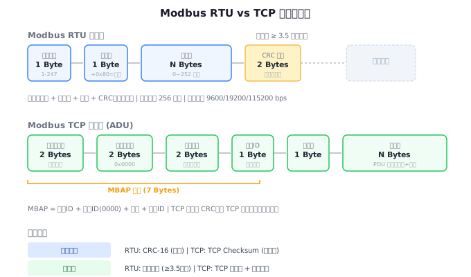
Modbus RTU is the original form of the Modbus protocol, designed in 1979 and running on RS-232 or RS-485 serial buses. In the industrial environment of that time, serial communication was the most economical and reliable solution. The RTU mode adopts compact binary encoding, with high transmission efficiency, and remains the most widely used Modbus variant in industrial fields to this day.
Modbus TCP was born in 1999 and was designed to adapt to the rapid development of Ethernet/IP networks. It encapsulates Modbus application layer data in TCP packets, enabling it to be transmitted through standard Ethernet infrastructure. Modbus TCP retains the function codes and data model of Modbus RTU, but removes the CRC check (with data integrity ensured by the TCP layer) and adds an MBAP header to handle IP network scenarios.
II. Comparison of Physical Layers
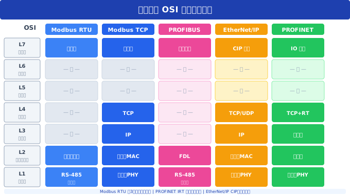
| Comparative Dimension | Modbus RTU | Modbus TCP |
|---|---|---|
| Physical medium | RS-485 (mainstream)/RS-232 (point-to-point) | Ethernet (twisted pair/fiber optic) |
| Topology | Bus type (daisy chain) | Star type (switch) |
| Maximum number of devices | 32 nodes (standard)/256 (enhanced transceiver) | Theoretically unlimited |
| Communication distance | 1200m (RS-485 @ 9600bps) | 100m (copper cable)/several kilometers (fiber optic) |
| Communication rate | 1200 ~ 115200 bps | 10/100/1000 Mbps |
| Anti-interference capability | Differential signaling, good | Excellent (nearly zero interference with fiber) |
| Cabling cost | Low (twisted pair) | High (switch, network cable/fiber) |
| Installation complexity | Simple | Relatively complex (requires IP configuration) |
2.1 Physical Characteristics of RS-485 Bus
RS-485 is the most commonly used physical layer standard for Modbus RTU. It employs differential signal transmission (A/B wires) and exhibits strong resistance to common-mode interference. The following are the key physical parameters of RS-485:
- Differential Voltage:Logic 1 corresponds to A wire voltage > B wire voltage (typically ≥ +200mV), while Logic 0 is the opposite
- Common-Mode Voltage Range:-7V to +12V
- Terminating Resistance:120Ω (matching characteristic impedance to prevent signal reflection)
- Bias Resistance:Maintains a certain logic state when the bus is idle to avoid misjudgment by the receiver
Common Wiring Errors:
- Inverting A/B wires - causing the slave station to fail to receive signals
- Using a star topology instead of a daisy chain - severe signal reflection
- Forgetting to add terminal resistors at both ends of the bus - unstable long-distance communication
- Mismatch in terminal resistance values - 120Ω is the standard value
III. Frame format comparison
3.1 Modbus RTU frame structure
Modbus RTU messages use "idle time ≥ 3.5 characters" as the frame interval marker. The frame structure is as follows:
┌──────────┬──────────┬──────────┬──────────┬──────────┐
│ ≥3.5字符  │ 地址 1B  │ 功能码 1B │ 数据 N字节 │ CRC 2B   │ ≥3.5字符  │
└──────────┴──────────┴──────────┴──────────┴──────────┘

示例(读保持寄存器):
3.5T  01  03  00 6B 00 03  76 87  3.5T
      ↑   ↑   └── 数据 ──┘  └ CRC ┘
     地址 功能               校验
Key features of RTU frames:
- No frame header or trailer markers, relying entirely on 3.5 characters of idle time to distinguish frame boundaries
- CRC-16 check covers the entire message
- Only one master station can be on the bus at a time
- Maximum frame length is 256 bytes (address + function code + data + CRC)
3.2 Modbus TCP frame structure (including MBAP header)
Modbus TCP adds a 7-byte MBAP header (Modbus Application Protocol Header) in front of the standard Modbus PDU (Protocol Data Unit):
┌──────────┬──────────┬──────────┬──────────┬──────────┬──────────┬──────────┐
│ 事务标识符 │ 协议标识符 │ 长度 2B   │ 单元标识符 │ 功能码 1B │ 数据 N字节 │
│   2B      │   2B      │          │  1B      │          │          │
└──────────┴──────────┴──────────┴──────────┴──────────┴──────────┘
                 ←────── MBAP 报头 (7 bytes) ──────→  ←─ PDU ─→

字段说明:
- 事务标识符 (Transaction ID): 主站生成,用于匹配请求和响应
- 协议标识符 (Protocol ID): 固定为 0x0000,表示 Modbus 协议
- 长度 (Length): 后续字节数(单元标识符 + 功能码 + 数据)
- 单元标识符 (Unit ID): 用于网关场景,标识下游从站地址
Example of a complete TCP frame:
读取从站 1 的保持寄存器 108-110(与 RTU 示例相同操作):

TCP 报文:
00 01  00 00  00 06  01  03  00 6B  00 03
└─┬──┘ └─┬──┘ └─┬──┘ └┬┘ └─┬──┘ └──┬──┘
事务ID 协议ID 长度=6 单元1 功能码 起址=107 数量=3
3.3 Detailed analysis of each field in the MBAP header
Transaction Identifier:
This is the most distinctive field in TCP mode. Since TCP supports full-duplex communication, the master station can send multiple requests simultaneously (in different TCP connections or different transactions on the same connection). The transaction identifier is used to match the response with the corresponding request. In simple scenarios with only one request/response, it is usually set to 0x0001 and incremented.
Protocol Identifier:
Fixed to 0x0000, indicating that this is the Modbus protocol. This field exists for possible future extensions - theoretically, multiple protocols can run on the same TCP port, and the protocol identifier is used to distinguish between them.
Length:
Indicates the number of all subsequent bytes, that is, "Unit Identifier (1 byte) + PDU (Function Code + Data)". The TCP layer does not have a 3.5-byte idle detection mechanism, and the length field is key to parsing frame boundaries in TCP mode.
Unit Identifier:
When Modbus TCP messages need to be forwarded to Modbus RTU devices on a serial link, the unit identifier acts as the RTU slave address. In scenarios where the device itself supports Modbus TCP, this field is usually set to 0x01 or 0xFF.
IV. Comparison of Addressing and Communication Mechanisms
| Comparison dimension | Modbus RTU | Modbus TCP |
|---|---|---|
| Addressing method | 8-bit slave address (1-247) | IP address + port number (default 502) |
| Communication mode | Half-duplex (only one side can send at a time) | Full-duplex (can send and receive simultaneously) |
| Concurrent connections | Not supported (bus sharing) | Supports multiple TCP connections |
| Number of master stations | 1 (bus arbitration is difficult) | Multiple (IP routing is inherently supported) |
| Broadcast support | Support (address 0) | Not directly supported (requires application layer processing) |
| Error detection | CRC-16 | TCP checksum |
V. In-depth Comparison of Performance Characteristics
5.1 Communication Rate Analysis
Taking a typical "read 10 hold registers" operation as an example, compare the time consumption of the two modes:
| Stage | Modbus RTU (9600bps) | Modbus TCP (100Mbps) |
|---|---|---|
| Request packet size | 8 bytes | 12 bytes (MBAP+PDU) |
| Request transmission time | 8 × 11 / 9600 ≈ 9.2ms | < 0.01ms |
| Response packet size | 25 bytes | 29 bytes |
| Response transmission time | 25 × 11 / 9600 ≈ 28.6ms | < 0.01ms |
| Slave processing time | 1~10ms | 1~10ms |
| Frame interval | 3.5 characters ≈ 4ms | 0 |
| Total time | ≈ 42-52ms | ≈ 1-10ms |
Conclusion:The single communication delay of Modbus TCP can be 5~50 times lower than that of RTU mode. In scenarios requiring high-frequency data acquisition (such as vibration monitoring, high-speed counting), TCP has significant performance advantages.
5.2 Concurrent communication of multiple devices
In Modbus RTU mode, since RS-485 is a shared bus, the master station must access the slave stations one by one in a polling manner. If there are 30 slave stations, each with a 50ms polling interval, one round would take 1.5 seconds - which is unacceptable for some real-time control scenarios.
In Modbus TCP mode, the master station can establish multiple TCP connections simultaneously and communicate with multiple slave stations concurrently. This makes TCP mode overwhelmingly advantageous in large-scale data acquisition systems.
VI. Introduction to Modbus ASCII Mode
In addition to RTU and TCP, Modbus also has an ASCII transmission mode. The ASCII mode encodes each byte as two printable ASCII characters (0-9, A-F), uses LRC check, and starts with a colon (:) and ends with carriage return and line feed (CRLF). Although it is the least efficient (the same amount of data requires approximately twice the number of bytes), the ASCII mode's messages are human-readable, which has unique advantages in debugging and teaching scenarios.
ASCII 模式报文示例(读保持寄存器 108,1 个):
RTU:   01 03 00 6B 00 01 [CRC]
ASCII: :0103006B0001[LRC]rn

→ 同样的 PDU,ASCII 需要 19 个字符(含帧头帧尾),RTU 只要 8 个字节
VII. Selection Decision Guide
7.1 Scenarios where Modbus RTU is preferred
- Existing RS-485 wiring:The factory site already has RS-485 buses laid out, and the cost of converting to Ethernet is too high
- The number of devices is small (<20):The polling delay is within an acceptable range
- The real-time requirement is not high:Second-level or minute-level data acquisition can meet the requirements
- Low-cost scenario:The device itself only has an RS-485 interface, and adding an Ethernet module increases costs
- The device spacing is large (100m~1200m):RS-485 can cover a long distance without the need for relaying
7.2 Scenarios where Modbus TCP is preferred
- High-speed data acquisition:Requires millisecond-level or even faster data refresh
- Large number of devices (>30):Polling delay has become a bottleneck
- Existing Ethernet infrastructure:The factory has already laid Ethernet cables
- Remote monitoring:Requires Internet access to devices (VPN may be combined)
- Multi-master access:Multiple supervisory computers need to access the same slave station simultaneously
- Integration with IT systems:Requires interfacing with IT systems such as databases, MES, and ERP
7.3 Hybrid architecture: Gateway bridging
In practical engineering, the most common solution is the hybrid architecture - using Modbus TCP to RTU gateway devices to connect a large number of RS-485 devices to Ethernet:
┌──────────┐    Modbus TCP     ┌──────────┐    Modbus RTU     ┌────┐┌────┐┌────┐
│   SCADA   │◄─────────────────►│  TCP/RTU  │◄───────────────►│从站1││从站2││从站N│
│  服务器   │    以太网          │  网关     │   RS-485 总线    └────┘└────┘└────┘
└──────────┘                    └──────────┘
This architecture combines the low device cost of RTU with the high performance and flexibility of TCP, making it the mainstream solution for current industrial IoT projects.
VIII. Security considerations
Modbus RTU is essentially "naked" - without any built-in security mechanism. On the RS-485 bus, any device connected to the bus can read or modify any message.
Modbus TCP also lacks built-in security mechanisms, but can be encrypted and authenticated through TLS (Transport Layer Security). The Modbus security protocol (using port 802) formally standardizes TLS encapsulation, providing:
- X.509v3 certificate authentication
- TLS Encrypted Communication
- Message Integrity Protection
In critical infrastructure, it is recommended to prioritize the use of Modbus Security Protocol (port 802) over standard Modbus TCP (port 502).
IX. Frequently Asked Questions (FAQ)
Q1: Can Modbus RTU devices be directly connected to a Modbus TCP network?
No, direct connection is not possible. Protocol conversion is required through a Modbus TCP/RTU gateway. The gateway is responsible for adding/removing MBAP headers and generating/verifying CRC checks.
Q2: Can Modbus RTU and Modbus TCP be used simultaneously on the same network?
Yes, they can be bridged through a gateway. One side of the gateway connects to Ethernet (Modbus TCP), while the other side connects to RS-485 bus (Modbus RTU). This is the most common hybrid architecture in industrial sites.
Q3: How can I determine whether a device is Modbus RTU or Modbus TCP?
Look at the physical interface: RS-232/RS-485 interface → Modbus RTU; RJ45 Ethernet interface → Modbus TCP. However, some devices have both interfaces (such as advanced PLCs), and you need to check the device manual to confirm the supported protocol.
Q4: What should I do if the default port 502 for Modbus TCP is blocked?
Most Modbus TCP devices support modifying the default port. Alternatively, you can use a VPN to establish a secure tunnel between firewalls. Modbus Security Protocol uses port 802 as an alternative.
10. Summary
Modbus RTU and Modbus TCP are not competitors but complements. RTU offers low cost and simple wiring at the device end, while TCP provides high speed and good scalability on the network side. Understanding the differences and respective application scenarios of the two is essential for making correct architectural decisions in industrial communication system design.
In a nutshell:RTU is the choice for "fieldbus", TCP is the choice for "information highway", and the gateway serves as the bridge that binds the two together.
Related Reading:Practical Guide to Modbus Serial Line Communication | Modbus TCP/IP Network Deployment and Optimization | In-depth Analysis of Modbus Security Protocol


Leave a Reply