
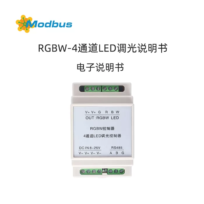
I. Technical Parameters
Operating Temperature: -20-60 ℃
Operating Voltage: DC12V-DC24V
Output Current: 16A (per circuit)
Rated Power: 12V:<500W 24V:<1000W
Output Circuit: Three Channels: Red (R), Green (G), Blue (B)
Output Color: 16777216 (256 * 256 * 256) types
output connections: common anode
static power consumption:<0.3W
external dimensions: 88mm * 54mm * 59mm (length, width, height)
communication methods: RS485
baud rate: 4800 9600 19200 38400 57600 115200
communication protocol: proprietary protocol, MODBUS-RTU protocol, custom protocol
2, Functional Features
Multiple scenarios:
- Color control, infinite automatic dimming
- Timer switch, full-color flashing, 7-color breathing
Flexible instructions:
- Custom instruction association control
- Comes with IO control and remote IO control
- Special instruction for color temperature adjustment of two-color tube lamp
- Single loop and multi loop timed switch control
- RGB light color control (up to 16 million colors)
- Configurable baud rate, power on memory function, and recovery enable
Rich input and output functions:
- 2 programmable input IO
- 6 programmable automatic scenarios
- Delay control, delay input technology (convenient for docking with human body sensing)
Multiple load docking capabilities:
- Standard Gongyang RGB LED strip/lamp
- Independent monochrome light strip, dual color temperature tube light
3, Seamless Multi Protocol
- Our company's self defined agreement (recommended)
- Industrial standard MODBUS protocol system
- Up to 6 user customizable protocols (to be used in conjunction with our company's customized protocols)
4, Reliable security performance
- RS485 communication control
- 55A original imported MOS
- Anti reverse power supply function, wide voltage 7-28V power supply
- For applications in strong interference environments, high-speed isolated communication version can be selected
- All use original components from large factories, with high cost-effectiveness. Industrial grade imported MCU has strong anti-interference ability
V. Terminal Description
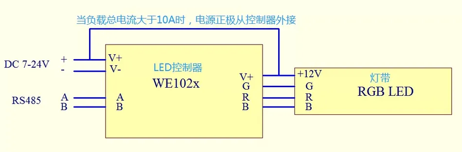
V+: Module power supply positive pole (wide voltage 7-26V power supply) V -: Module power supply negative pole A: RS485 A terminal B: RS485 B terminal V+: Common positive RGB lamp positive pole (connected to the power supply V+) R: LED red (negative pole) G: LED green (negative pole) B: LED blue (negative pole)
VI. Controller Options Table
| Model | Communication Interface | Communication Isolation | Load Capacity | Single Loop Load Capacity | Power Supply |
|---|---|---|---|---|---|
| WE102 | RS485 | None | 15A | 5A | - |
| WE102A | RS485 | None | 20A | 5A | - |
| WE102B | RS485 | have have None | 15A | 5A | - |
| WE102C | RS485 | None | 20A | 5A | - |
| WE102D | RS485 | None | 6A | 2A | - |
| WE102E | RS485 | Value | 8A | 2A | - |
| WE102F | RS485 | Debugging assistant download | 6A | 2A | - |
Explanation:
- The controller is a low-voltage DC controller, with a default supply voltage of DC: 7-28V.Suggest 12V or 24V. When applied to a power supply voltage greater than 28V, it is necessary to contact customer service personnel in advance for customization. The output port of the controller is a high-power MOS transistor, and it is strictly prohibited to short-circuit the load (output and V+). To prevent short circuit of the load, please choose a fuse tube that is suitable for the load power for protection. The load voltage of the controller should be consistent with the supply voltage.
- The output port of the controller is a high-power MOS transistor, and it is strictly prohibited to short-circuit the load (output and V+). To prevent short circuit of the load, please choose a fuse tube that is suitable for the load power for protection.
- The load voltage of the controller should be consistent with the supply voltage.
7. Communication Protocol Description
Self owned Protocol
This protocol is used to configure the RS485 communication parameters of the device. All commands start with 0xA5 and end with 0x5A.checksumstarts fromlength byteStart, toBefore checksum byteThe cumulative sum of all bytes (usually the lower 8 bits).
1. Set communication address (0xB0)
- Function:Change the communication address of the device.
- Important note:
o If there is anaddress dip switchon the device, this commandis invalidand will return a failure (0xB3). The address must be set using a dip switch.
oDial switch operation:
- Factory default: All switches are on the non numeric side (1), with an address of 0xFF.
- Set Address: Turn the switch to the digital side to indicate that the bit is 0, otherwise it is 1.
- Power off operation is required!Live operation may damage the controller. After setting the dip switch
- ,will be powered on again andwill take effect.
o Use this command to set the address:No need to power off, immediate effect, the new address will be saved.
- Send Command (Host ->Device):
| Byte Position | Field | Value (Hexadecimal) | Description |
| 1 | Starting Code | 0xA5 | Fixed Starting Symbol |
| 2 | Length | 0x04 | The length of the command data portion (old address+command word+new address=3 bytes) |
| 3 | Old Address | 0xXX | CurrentAddress used for device communication (0x00-0FF) |
| 4 | Command word | 0xB0 | Address setting command |
| 5 | New address | 0xXX | To be setNew address(0x00-0FF) |
| 6 | Checksum | 0xXX | Accumulated sum fromlength (0x04)tonew address(SUM (0x04, old address, 0xB0, new address)) |
| 7 | End code | 0x5A | Fixed end symbol |
·
- Receive response (device ->host):
| Byte position | Field | Value (hexadecimal) | Description |
| 1 | Starting code | 0xA5 | Fixed starting character |
| 2 | Length | 0x03 | This response data part length (new address+command word=2 bytes) |
| 3 | New address | 0xXX | The address currently used by the device (i.e. the set address) |
| 4 | Command word | 0xB2/0xB3 | 0xB2=Successful Setting 0xB3=Failed Setting(usually caused by the presence of a dip switch) |
| 5 | Checksum | 0xXX | Accumulated Sum fromLength (0x03)toCommand Word(SUM (0x03, new address, command word)) |
| 6 | End Code | 0x5A | Fixed End Symbol |
·
2. Query Communication Address (0xB1)
·Function:Query the current communication address of the device.
·Send Command (Host ->Device):
| Byte Position | Field | Value (Hexadecimal) | Description |
| 1 | Start Code | 0xA5 | Fixed starting symbol |
| 2 | Length | 0x03 | The length of the data portion of this command (address+command word=2 bytes) |
| 3 | Address | 0xXX / 0xFF | Local address(Single query) or0xFF(Broadcast query, all devices will respond to the address) |
| 4 | command word | 0xB1 | Address query command |
| 5 | checksum | 0xXX | FromLength (0x03)Go toCommand word (0xB1)Sum of Accumulation (SUM (0x03, Address, 0xB1)) |
| 6 | End code | 0x5A | Fixed End Symbol |
·
·Receive response (device ->host):
| Byte position | field | Value (hexadecimal) | Explanation |
| 1 | Starting code | 0xA5 | Fixed starting symbol |
| 2 | Length | 0x03 | The length of this response data section (address+command word=2 bytes) |
| 3 | Address | 0xXX | DeviceCurrentCommunication Address |
| 4 | Command Word | 0xB2 | Address Query Reply Command (Fixed as Successful Reply) |
| 5 | Checksum | 0xXX | Length from(0x03)Go toCommand word (0xB2)Sum of Accumulation (SUM (0x03, Address, 0xB2)) |
| 6 | End code | 0x5A | Fixed End Symbol |
·
3. Set the communication baud rate (0xB4)
- Function:Change the RS485 communication baud rate of the device.
- Send Command (Host ->Device):
| Byte Position | Field | Value (hexadecimal) | Explanation |
| 1 | Starting code | 0xA5 | Fixed starting symbol |
| 2 | Length | 0x04 | The length of the data portion of this command (address+command word+baud rate=3 bytes) |
| 3 | Address | 0xXX | CurrentlyAddress used for communication with the device (0x00-0FF) |
| 4 | Command Word | 0xB4 | Baud Rate Setting Command |
| 5 | Baud Rate | 0x01-0x05 | 1=4800, 2=19200, 3=38400, 4=57600, 5=115200, Other=9600 |
| 6 | Checksum | 0xXX | Length (0x04) fromtoGo toBaud RateSum of Sum (0x04, Address, 0xB4, Baud Rate) |
| 7 | End code | 0x5A | Fixed End Symbol |
·
- Receive response (device ->host):
| Byte position | field | Value (hexadecimal) | Explanation |
| 1 | Starting code | 0xA5 | Fixed starting symbol |
| 2 | Length | 0x04 | This response data part length (address+command word+baud rate=3 bytes) |
| 3 | Address | 0xXX | Device Address |
| 4 | Command Word | 0xB6/0xB7 | 0xB6=Setting Successful 0xB7=Setting Failed |
| 5 | Baud rate | 0x01-0x05 | The baud rate currently being used by the device(1=4800, 2=19200, 3=38400, 4=57600, 5=115200, others=9600) |
| 6 | checksum | 0xXX | FromLength (0x04)Go toBaud rateSum of Sum (0x04, Address, Command Word, Baud Rate) |
| 7 | End code | 0x5A | Fixed End Symbol |
·
4. Query communication baud rate (0xB5)
·Function:Query the current RS485 communication baud rate of the device.
·Send command (Host ->Device):
| Byte position | field | Value (hexadecimal) | Explanation |
| 1 | Starting code | 0xA5 | Fixed starting symbol |
| 2 | Length | 0x03 | The length of the data portion of this command (address+command word=2 bytes) |
| 3 | Address | 0xXX / 0xFF | Local address(Single query) or0xFF(Broadcast inquiry) |
| 4 | command word | 0xB5 | Baud rate query command |
| 5 | checksum | 0xXX | FromLength (0x03)Go toCommand word (0xB5)Sum of Accumulation (SUM (0x03, Address, 0xB5)) |
| 6 | End code | 0x5A | Fixed End Symbol |
·
·Receive response (device ->host):
| Byte position | field | Value (hexadecimal) | Explanation |
| 1 | Starting code | 0xA5 | Fixed starting symbol |
| 2 | Length | 0x04 | The length of this response data section (address+command word+baud rate=3 bytes) |
| 3 | Address | 0xXX | Device address |
| 4 | command word | 0xB6 / 0xB7 | 0xB6=query successful 0xB7=query failed(uncommon) |
| 5 | Baud rate | 0x01-0x03 | The baud rate currently being used by the device (1=19200, 2=57600, 3=115200, others=9600) |
| 6 | checksum | 0xXX | FromLength (0x04)Go toBaud rateSum of Sum (0x04, Address, Command Word, Baud Rate) |
| 7 | End code | 0x5A | Fixed End Symbol |
·
oAttention:Define the baud rate values in the query response (1=19200, 2=57600, 3=115200) and set commands (1=4800, 2=19200, 3=38400...)DifferentAnd the scope is smaller. Other=9600 is the same.
5. Set whether to reply with ACK (0xB8)
·Function:Set whether the device responds with an acknowledgement (ACK) after receiving a command.
o0x00 (default):replies withACK.
o0x01: does not reply withACK.
·Send Command (Host ->Device):
| Byte Position | Field | Value (Hexadecimal) | Description |
| 1 | Start Code | 0xA5 | Fixed Start Symbol |
| 2 | Length | 0x04 | The length of the data portion of this command (address+command word+reply to close=3 bytes) |
| 3 | Address | 0xXX | The currentaddress used for communication with the device (0x00-0FF) |
| 4 | Command word | 0xB8 | ACK reply setting command |
| 5 | Reply to close | 0x00/0x01 | 0=Reply ACK (default) 1=No ACK Reply |
| 6 | Checksum | 0xXX | Accumulated Sum fromLength (0x04)toReply Close(SUM (0x04, Address, 0xB8, Reply Close)) |
| 7 | End Code | 0x5A | Fixed Bundle Symbol |
·
·Receive response (device ->host):
| Byte position | field | Value (hexadecimal) | Explanation |
| 1 | Starting code | 0xA5 | Fixed starting symbol |
| 2 | Length | 0x04 | The length of this response data section (address+command word+reply closed=3 bytes) |
| 3 | Address | 0xXX | Device address |
| 4 | command word | 0xBA / 0xBB | 0xBA=successfully set 0xBB=Setting failed |
| 5 | Reply to Close | 0x00 / 0x01 | The current ACK reply status of the device(0=reply, 1=no reply) |
| 6 | checksum | 0xXX | FromLength (0x04)Go toReply to CloseSum of Sum (0x04, Address, Command Word, Reply Close) |
| 7 | End code | 0x5A | Fixed End Symbol |
·
6. Check if an ACK (0xB9) has been replied to
- Function:Check if the device is currently responding with an ACK.
- Important Notice:If the device has been set to not reply with ACK (0x01), after sending this query command, the deviceI won't replyAny data (communication light may flash, but there is no output from the serial port).
- Send command (Host ->Device):
| Byte position | field | Value (hexadecimal) | Explanation |
| 1 | Starting code | 0xA5 | Fixed starting symbol |
| 2 | Length | 0x03 | The length of the data portion of this command (address+command word=2 bytes) |
| 3 | Address | 0xXX / 0xFF | Local address(Single query) or0xFF(Broadcast inquiry) |
| 4 | command word | 0xB9 | ACK reply query command |
| 5 | checksum | 0xXX | Accumulated sum oflength (0x03)tocommand word (0xB9)(SUM (0x03, address, 0xB9)) |
| 6 | End code | 0x5A | Fixed end symbol |
·
- Receive response (device ->host): (only received when device is set to reply ACK)
| Byte position | Field | Value (Hexadecimal) | Description |
| 1 | Starting Code | 0xA5 | Fixed Starting Symbol |
| 2 | Length | 0x04 | This Response Data Part Length (Address+Command Word+Reply Close=3 bytes) |
| 3 | Address | 0xXX | Device Address |
| 4 | command word | 0xBA / 0xBB | 0xBA=query successful 0xBB=query failed(uncommon) |
| 5 | Reply to Close | 0x00 / 0x01 | The current ACK reply status of the device(0=reply, 1=no reply) |
| 6 | checksum | 0xXX | FromLength (0x04)toReply to closeAccumulated sum (SUM (0x04, address, command word, reply to close) |
| 7 | End code | 0x5A | Fixed end symbol |
·
7. Set the power-off output state memory function (0xBC)
- Function:Control whether the device remembers and restores the output state before power-off.
o0x00 (default):Do not remember. The next power on output will be in default state.
o0x01: Memory. Restore the output state before the power outage during the next power on.
- Explanation:After activating the memory function (0x01), the device willAfter receiving and executing a valid output control command next time, willThe output status at that timeSave it. After a power outage, the next power on will restore this state.
- Send Command (Host ->Device):
| Byte Position | Field | Value (Hexadecimal) | Explanation |
| 1 | Starting code | 0xA5 | Fixed starting symbol |
| 2 | Length | 0x04 | The length of the data portion of this command (address+command word+memory function=3 bytes) |
| 3 | Address | 0xXX | CurrentlyAddress used for communication with the device (0x00-0FF) |
| 4 | command word | 0xBC | Memory function setting command |
| 5 | memory function | 0x00 / 0x01 | 0=No memory (default) 1=Memory |
| 6 | checksum | 0xXX | FromLength (0x04)Go toMemory functionSum of Accumulation (SUM (0x04, Address, 0xBC, Memory Function)) |
| 7 | End code | 0x5A | Fixed End Symbol |
·
- Receive response (device ->host):
| Byte position | field | Value (hexadecimal) | Explanation |
| 1 | Starting code | 0xA5 | Fixed Start Symbol |
| 2 | Length | 0x04 | This response data part length (address+command word+memory function=3 bytes) |
| 3 | Address | 0xXX | Device Address |
| 4 | Command Word | 0xBE/0xBF | 0xBE=Setting Successful 0xBF=Setting Failed |
| 5 | Memory Function | 0x00/0x01 | Current Memory Function Status of Device(0=Not Memory, 1=Memory) |
| 6 | Checksum | 0xXX | Accumulated Sum fromLength (0x04)toMemory Function(SUM (0x04, Address, Command Word, Memory Function)) |
| 7 | End Code | 0x5A | Fixed End Symbol |
·
8. Query Power Off Output Status Memory Function (0xBD)
- Function:Query the current power off output status memory function status of the device.
- Send Command (Host ->Device):
| Byte Position | Field | Value (Hexadecimal) | Description |
| 1 | Start Code | 0xA5 | Fixed Start Symbol |
| 2 | Length | 0x03 | The length of the data portion of this command (address+command word=2 bytes) |
| 3 | Address | 0xXX/0xFF | Local Address(single query) or0xFF(broadcast query) |
| 4 | Command Word | 0xBD | Memory Function Query Command |
| 5 | Checksum | 0xXX | Accumulated Sum fromLength (0x03)toCommand Word (0xBD)(SUM (0x03, Address, 0xBD) |
| 6 | End Code | 0x5A | Fixed Bundle Symbol |
·
- Receive Response (Device ->Host):
| Byte position | field | Value (hexadecimal) | Explanation |
| 1 | Starting code | 0xA5 | Fixed starting symbol |
| 2 | Length | 0x04 | The length of this response data section (address+command word+memory function=3 bytes) |
| 3 | Address | 0xXX | Device Address |
| 4 | Command Word | 0xBE/0xBF | 0xBE=Query Successful 0xBF=Query Failed(uncommon) |
| 5 | Memory Function | 0x00/0x01 | Current Memory Function Status of the Device(0=Not Memory, 1=Memory) |
| 6 | Checksum | 0xXX | Accumulated sum fromlength (0x04)tomemory function(SUM (0x04, address, command word, memory function)] |
| 7 | End code | 0x5A | Fixed end symbol |
·
Summary key:
- Start/End code:All commands start with 0xA5 and end with 0x5A.
- Length:refers to the number of data bytes fromtoafter the length byte of.before the checksum byte of
- checksum:The calculation range is fromlength byteto all bytes beforeBefore checksum byteAll the bytes. Be sure to calculate correctly.
- Address:
- Use it when setting/querying specific devicesCurrent address.
- The broadcast address 0xFF can be used to query commands (address, baud rate, ACK status, memory function), and all devices will respond (note conflicts). When
- dip switch is present, the address setting command is invalid and dangerous (power off operation is required).When present, the address setting command is invalid and dangerous (requiring power-off operation).
- ACK Reply:If the device is set to not reply to ACK (0x01), sending a query ACK status command (0xB9) will not receive any response from..
- Memory function: Afteris turned on, it needs to be sentAn effective output control command, will the device save the current output state ofThe output status at that timeUsed for power outage recovery.
Complete documentation of communication protocol for WE-10x series LED controller
1. Overview
The WE-10x series LED controller is mainly used to control the color and brightness of low-voltage RGB lamps and single/dual color lamps. Supports standard RS485 communication interface, and data exchange adopts hexadecimal protocol. In the specific command format, each part is measured in bytes. Other baud rates can be configured through software. After configuration, it will respond to commands at the latest baud rate.
Factory default parameters
- Communication baud rate: 9600bps
- Data bits: 8 digits
- Stop Bit: 1 Bit
- Check Bit: None
- Device Address: 0x000-0xFE (Broadcast Address 0xFF)
2. Instruction Format Description
Basic Instruction Format
[起始码] [长度] [地址] [命令字] [有效数据] [校验和] [结束码]Field Description
| Field | Description | Resource prices | Remarks |
|---|---|---|---|
| Starting code | Data frame start flag | 0xA5 | fixed value |
| Length | The sum of bytes for all communication content except for the start code, length, and end code | 0xXX | The sum of byte lengths from 'address' to' checksum ' |
| Address | Controller address | 0x00-0xFE | Broadcast address 0xFF does not respond |
| command word | Function code of command | 0xA0-0xA1 | Refer to each instruction protocol for details |
| valid data | Effective data in communication | - | The data content definitions of each instruction are detailed in the respective instruction protocols |
| checksum | Arithmetic accumulation of length, address, command word, and valid data | 0xXX | Ignore the overflow part and take the lower 8 bits; Can be replaced with 0xEE (without verification) |
| termination code | End flag of data frame | 0x5A | fixed value |
3. Specific instruction instructions
3.1 Setting RGB (RGBW) values
FunctionAccording to the principle of three primary colors, set the values of RGB, and the W value is an optional brightness value.
Sending instruction format
A5 [长度] [地址] A0 [R值] [G值] [B值] [W值] [校验和] 5ALength description:
- RGB type controller: 0x06 (6 bytes)
- RGBW type controller: 0x07 (7 bytes)
Parameter Range:
- R value: 0x00-0FF (red output value)
- G-value: 0x00-0FF (green output value)
- B value: 0x00-0FF (blue output value)
- W value: 0x00-0FF (white output value, only valid for RGBW type)
Receive instruction format
A5 [长度] [地址] A2 [R值] [G值] [B值] [W值] [校验和] 5ALength description:
- RGB type controller:0x06(6 bytes)
- RGBW type controller:0x07(7 bytes)
Example
RGBW type controller, red and white lights on:
- send out:
A5 07 FF A0 FF 00 00 FF EE 5A - receive:
A5 06 00 A2 FF 00 00 A7 5A
3.2 Querying RGB (RGBW) Values
FunctionQuery the current RGB (W) output value of the controller.
Sending Instruction Format
A5 03 [地址] A0 [校验和] 5AReceive Instruction Format
A5 [长度] [地址] A2 [R值] [G值] [B值] [W值] [校验和] 5AExample
- Send:
A5 03 FF A0 EE 5A - Receive:
A5 06 00 A2 FF 00 00 A7 5A
3.3 Controller Scene Function Settings
Function: Set various scene effects, including breathing, flashing, dimming, single step dimming, switches, etc.
Instruction Format
A5 [长度] [地址] A1 [场景码] [功能码] [场景内容] [校验和] 5AParameter Description:
- Scene Code:0x01 (breathing light), 0x02 (flashing), 0x03 (dimming), 0x04 (single step dimming), 0x05 (switch)
- Function code: Please refer to the corresponding scene command table
- Scene content: Please refer to the corresponding scene command table
Receiving instruction format
is the same as the receiving command format in 3.1.
3.3.1 Breathing Light Scene Content Table
Function Code: 0x01Scene Content Format:
[颜色码] [速度] [亮度]Color Code Description:
- 0x01: Red Light Breathing
- 0x02: Green light breathing
- 0x03: Blue light breathing
- 0x04: White light breathing (RGB type is RGB synthesized white breathing, RGBW type is W output breathing)
- 0x05: RGB respiration
- 0x06: Yellow light breathing
- 0x07: Purple Lamp Breathing
Example
- Red light breathing:
A5 08 FF A1 01 01 01 00 FF EE 5A - Green light breathing:
A5 08 FF A1 01 02 01 00 FF EE 5A - Blue light breathing:
A5 08 FF A1 01 03 01 00 FF EE 5A - White light breathing:
A5 08 FF A1 01 04 01 00 FF EE 5A - RGB respiration:
A5 08 FF A1 01 05 01 00 FF EE 5A - Yellow light breathing:
A5 08 FF A1 01 06 01 00 FF EE 5A - Purple lamp breathing:
A5 08 FF A1 01 07 01 00 FF EE 5A
3.3.2 Flash Scene Content Table
Function code: 0x02 Scene content format:
[颜色码] [速度] [亮度] [其他参数]Example
- Red light flashing:
A5 08 FF A1 02 01 01 02 FF EE 5A - Green light flashing:
A5 08 FF A1 02 02 01 02 FF EE 5A - Blue light flashing:
A5 08 FF A1 02 03 01 02 FF EE 5A - White light flashing:
A5 08 FF A1 02 04 01 02 FF EE 5A - 7-color flashing:
A5 0B FF A1 02 06 01 02 FF FF FF FF EE 5A - Yellow light flashing:
A5 0B FF A1 02 07 01 02 FF FF FF EE 5A - Purple light flashing:
A5 0B FF A1 02 08 01 02 FF FF FF FF EE 5A
3.3.3 Dimming Scene Content Table
Function code: 0x03 Scene content format:
[颜色码] [目标亮度] [速度]Example
- Red light dimming:
A5 07 FF A1 03 01 FF 01 EE 5A - Green light dimming:
A5 07 FF A1 03 02 FF 01 EE 5A - Blue light dimming:
A5 07 FF A1 03 03 FF 01 EE 5A - White light dimming:
A5 07 FF A1 03 04 FF 01 EE 5A(Valid only for RGBW output models) - Synchronous dimming (full brightness):
A5 0A FF A1 03 05 FF FF FF FF 01 EE 5A - Synchronous dimming (fully off):
A5 0A FF A1 03 05 00 00 00 00 01 EE 5A
3.3.4 Single Step Dimming Scene Content Table
Function code: 0x04 Scene content format:
[操作码]Operation code description:
- 0x01: Red light brightness plus 1
- 0x81: Red light brightness reduced by 1
- 0x02: Green light brightness plus 1
- 0x82: Green light brightness reduced by 1
- 0x03: Blue light brightness plus 1
- 0x83: Blue light brightness minus 1
- 0x04: White light brightness plus 1 (RGBW effective)
- 0x84: White light brightness minus 1 (RGBW effective)
- 0x05: RGBW brightness plus 1 (RGBW effective)
- 0x85: RGBW brightness reduced by 1 (RGBW effective)
Example
- Red light brightness plus 1:
A5 05 FF A1 04 01 EE 5A - Reduce the brightness of the red light by 1:
A5 05 FF A1 04 81 EE 5A - Green light brightness plus 1:
A5 05 FF A1 04 02 EE 5A - Green light brightness minus 1:
A5 05 FF A1 04 82 EE 5A - Blue light brightness plus 1:
A5 05 FF A1 04 03 EE 5A - Blue light brightness minus 1:
A5 05 FF A1 04 83 EE 5A - White light brightness plus 1:
A5 05 FF A1 04 04 EE 5A - White light brightness minus 1:
A5 05 FF A1 04 84 EE 5A - RGBW brightness plus 1:
A5 05 FF A1 04 05 EE 5A - RGBW Brightness Decrease 1:
A5 05 FF A1 04 85 EE 5A
3.3.5 Switch Scene Content Table
Function Code: 0x05Scene Content Format:
[颜色码] [延时] [操作类型] [状态值]Operation Type Description:
- 0x01: Single Channel Control
- 0x05: GBW Simultaneous Control
State Value Description:
- 0x01: Open
- 0x00: Off
- 0x02: Switch switching (send once to turn on, next time to turn off, loop)
Example
- Red light on:
A5 08 FF A1 05 01 00 01 01 EE 5A - Red light off:
A5 08 FF A1 05 01 00 01 00 EE 5A - Red light switch switching:
A5 08 FF A1 05 01 00 01 02 EE 5A - White light on:
A5 08 FF A1 05 04 00 01 01 EE 5A - White light off:
A5 08 FF A1 05 04 00 01 00 EE 5A - White light switch switching:
A5 08 FF A1 05 04 00 01 02 EE 5A - RGBW on:
A5 0B FF A1 05 05 00 01 01 01 01 01 EE 5A - RGBW off:
A5 0B FF A1 05 05 00 01 00 00 00 00 EE 5A - RGBW switch switching:
A5 0B FF A1 05 05 00 01 02 02 02 02 EE 5A
4. Precautions
- Broadcast address 0xFF is used to send commands to all devices, but the devices do not respond to broadcast commands
- Checksum calculation: the accumulated sum from the "length" byte to the byte before the "checksum", taking the lower 8 bits
- Using 0xEE as the checksum can skip the verification calculation
- RGB type controllers ignore the W value parameter
- The white effect in scene functions is implemented differently on RGB and RGBW type controllers
LED controller MODBUS protocol complete document
1. Overview
The WE-10x series LED controller is mainly used to control the color and brightness of low-voltage RGB lamps and single/dual color lamps. It supports standard RS485 communication interface and data exchange adopts standard MODBUS RTU protocol. For detailed instruction generation and parsing methods, you can refer to the register table in this article in conjunction with the "MODBUS Protocol Chinese Version".
1.1 Register Address Table
Note:Keep the corresponding addressing address of register 1 as 0x0000, keep the corresponding addressing address of register 2 as 0x0001, and so on.
| Register Name | Addressing address | Functional Description | value range | access permission | Remark |
|---|---|---|---|---|---|
| Output value R | 0x0000 | Red channel output value | 0x0000-0x00FF | read and write | RGB value range 0-255 |
| Output value G | 0x0001 | Green channel output value | 0x0000-0x00FF | read and write | RGB value range 0-255 |
| Output value B | 0x0002 | Blue channel output value | 0x0000-0x00FF | read and write | RGB value range 0-255 |
| Output value W | 0x0003 | White channel output value | 0x0000-0x00FF | read and write | W value range 0-255 |
| Device address | 0x0004 | Device communication address | 0x0001-0x00FF | Read and write | 1-255 |
| Baud rate | 0x0005 | Communication baud rate | 0-5 | read and write | See baud rate description |
| Prohibit response | 0x0006 | Do you prohibit response | 0-1 | Read and write | 0: Allow, 1: Prohibit |
| Power off memory | 0x0007 | Power off state memory | 0-1 | Read and write | 0: No Memory, 1: Memory |
| Scene Function | 0x0008 | Scene Function Settings | - | Read/Write | See Scene Function Description |
Baud Rate Setting Value Description:
- 0: 4800bps
- 1: 9600bps (default value)
- 2: 19200bps
- 3: 38400bps
- 4: 57600bps
- 5: 115200bps
2. Instruction List
2.1 Controller Parameter Settings
Function Code:0x06 (Write to Single Register) Controller parameters include device address, baud rate, disable response, power-off memory, and other parameters. When the device address is unclear, parameter settings can be made through the broadcast address.Instruction format:
[设备地址] [功能码0x06] [寄存器地址高8位] [寄存器地址低8位] [数据高8位] [数据低8位] [CRC校验低8位] [CRC校验高8位]Example: Controller original address is 0x01, change address to 0x03
- Send command:
01 06 00 04 00 03 88 0A - Receive response:
01 06 00 04 00 03 88 0A
Explanation:
- When setting the address, the slave address returned by the command is the same as the received command, both are 0x01
- The new slave address will be valid for the next communication. After setting, please use the new slave address 0x03
- Device address initialization settings can be performed using broadcast address 0x00
2.2 Controller parameter query
Function code:0x03 (read and hold register)Note:When the "disable response" function is enabled, the query does not return.Instruction format:
[设备地址] [功能码0x03] [起始地址高8位] [起始地址低8位] [寄存器数量高8位] [寄存器数量低8位] [CRC校验低8位] [CRC校验高8位]Example: Query controller address
- Send command:
01 03 00 04 00 01 C5 CB - Receive response:
01 03 02 00 01 79 84
Response description:
01: Device address03: Function code02: Return data byte count00 01: Query parameter value (here device address 0x0001)79 84: CRC verification
2.3 Controller output value setting
Function code:0x10 (write multiple registers) Set the values of four output circuits. When the load is an RGB light fixture, the corresponding color can be displayed. When the load is a monochrome light fixture, the corresponding brightness value of each output will be displayed. This command is for RGBW format setting. When the controller is set to 'No W output model', the W value will be ignored by the controller.Instruction format:
[设备地址] [功能码0x10] [起始地址高8位] [起始地址低8位] [寄存器数量高8位] [寄存器数量低8位] [数据字节数] [数据1高8位] [数据1低8位] ... [CRC校验低8位] [CRC校验高8位]Example 1: Set R circuit output to 0xFF
- Send command:
01 10 00 00 00 04 08 00 FF 00 00 00 00 00 00 B9 75 - Receive response:
01 10 00 00 00 04 C1 CA
Example 2: Set G circuit output to 0xFF
- Send command:
01 10 00 00 00 04 08 00 00 00 FF 00 00 00 00 A2 6E - Receive response:
01 10 00 00 00 04 C1 CA
Example 3: Set B circuit output to 0xFF
- Send command:
01 10 00 00 00 04 08 00 00 00 00 00 FF 00 00 86 4A - Receive response:
01 10 00 00 00 04 C极 CA
Example 4: Set W circuit output to 0xFF
- Send command:
01 10 00 00 00 04 08 00 00 00 00 00 00 00 FF F6 3A - Receive response:
01 10 00 极 00 00 04 C1 CA
Example 5: Set all circuit outputs to 0xFF
- Send command:
01 10 00 00 00 04 08 00 FF 00 FF 00 FF 00 FF DD 11 - Receive response:
01 10 00 00 00 04 C1 CA
Example 6: Set all circuit outputs to 0x00
- Send command:
01 10 00 00 00 04 08 00 00 00 00 00 00 00 00 B6 7A - Receive response:
01 10 00 00 00 04 C1 CA
2.4 Controller output value query
Function code:0x03 (read hold register)
Example: Query the output value of the controller address 0x01
- Send command:
01 03 00 00 00 04 44 09 - Receive response:
01 03 08 00 FF 00 FF 00 FF 00 00 BE FC
Response description:
- Return in RGBW order
- The above example returns values: R=0x00FF, G=0x00FF, B=0x00FF, W=0x0000
- Each channel value occupies 2 bytes (16 bits), but the valid value For the lower 8 digits
2.5 Controller Scene Function Settings
Function Code:0x10 (write multiple registers) Includes functions such as breathing, flashing, dimming, and independent switching.Note:When it is a "RGB output model", any white function is synthesized, for example, the LED strip is RGB synthesized white breathing; When it is the "RGBW model", the light strip directly outputs the breathing light from W.
Breathing Light Function Writing Content Table
| Function | Writing Value | Description |
|---|---|---|
| Red Light Breathing | 0x0001 | Red Breathing Effect |
| Green Breathing | 0x0002 | Green Breathing Effect |
| Blue Breathing | 0x0003 | Blue Breathing Effect |
| White Breathing | 0x0004 | White Breathing Effect |
| Purple Breathing | 0x0005 | Purple Breathing Effect |
| Yellow Light Breathing | 0x Pole 6 | Yellow Breathing Effect |
| Blue Light Breathing | 0x0007 | Blue Breathing Effect |
| Colorful Breathing | 0x0008 | Colorful Breathing Effect |
Flashing Function Write Content Table
| Function | Write Value | Description |
|---|---|---|
| Red Flashing | 0x0001 | Red Flashing Effect |
| Green Flashing | 0x0002 | Green Flashing Effect |
| Blue Flashing | 0x0003 | Blue Flashing Effect |
| White Flashing | 0x0004 | White Flashing Effect |
| 7-Color Flashing | 0x0005 | 7-Color Loop Flashing |
Dimming Function Writing Content Table
| Parameters | Address Offset | Description |
|---|---|---|
| Function Selection | 0x0000 | Dimming Function Identification (0x0003) |
| R Brightness Value | 0x0001 | Red Brightness (0x00-0FF) |
| G Brightness Value | 0x0002 | Green Brightness (0x00-0FF) |
| B Brightness Value | 0x0003 | Blue Brightness (0x00-0FF) |
| W Brightness Value | 0x0004 | White Brightness (0x00-0FF) |
| Dimming Speed | 0x0005 | Dimming speed value |
Switch function writing content table
| Function | Writing value | Description |
|---|---|---|
| Red light switch | 0x0001 | Red switch switching |
| Green light switch | 0x0002 | Green switch switching |
| Blue light switch | 0x0003 | Blue switch switch |
| White light switch | 0x0004 | White switch switch |
| All switches | 0x0005 | All channel switches |
Example 1: Set the controller to purple light breathing
- Send command:
01 10 00 08 00 05 0A 00 01 00 00 00 00 00 00 00 00 00 00 81 C8 - Receive response:
01 10 00 08 00 05 81 C8
Example 2: 7-Color Flashing
- Send Command:
01 10 00 08 00 08 10 00 02 01 00 02 00 FF FF FF 00 5B 4C - Receive Response:
01 10 00 08 00 08 40 0D
Example 3: Red Light Brightness Set to 0x0F, Green Light Brightness Set to 0xFF, Blue Light Brightness Set to 0x80, White Light Brightness Set to 0xA0
- Send Command:
01 10 00 08 00 07 0E 00 03 极 05 00 0F 00 FF 00 80 00 A0 00 01 1D C1 - Receive Response:
01 10 00 08 00 07 00 09
Example 4: Controller Red Light Switch Conversion (Send this command once to turn on, next time to turn off, loop)
- Send Command:
01 10 00 08 00 05 0A 00 05 00 01 00 00 00 00 00 02 A6 61 - Receive Response:
01 10 00 08 00 05 81 C8
Example 5: RGBW All Delay 1 Second Switch Conversion
- Send Command:
01 10 00 08 00 08 10 00 05 00 05 00 00 00 01 00 02 00 02 00 02 00 02 46 13 - Received response:
01 10 00 08 00 08 40 0D
3. Default Communication Parameters
- Device Address:0x01 (default)
- Baud Rate:9600bps (8-bit data bit, 1-bit stop bit, no checksum)
- No response allowed:0 (allow response)
- Power off memory:0 (no memory output state)
4. Precautions
- When using the broadcast address 0x00, all devices will respond, which may cause communication conflicts
- After setting the "disable response" function, the device will not respond to any query commands
- The output value range of RGBW is 0x0000-0x00FF, and the actual effective value is the lower 8 bits
- When setting scene functions, please select the appropriate function according to the controller model (RGB or RGBW)


11111