
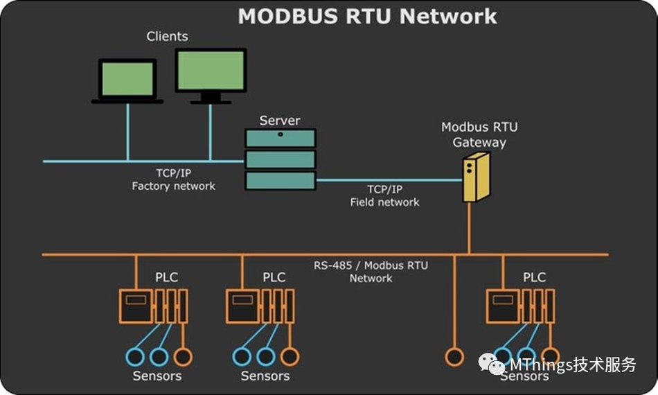
The wiring of Modbus RS485 belongs to weak current operation, which is different from power wiring. If the electrician is not an expert in fieldbus network, the communication network may not function properly in the end.
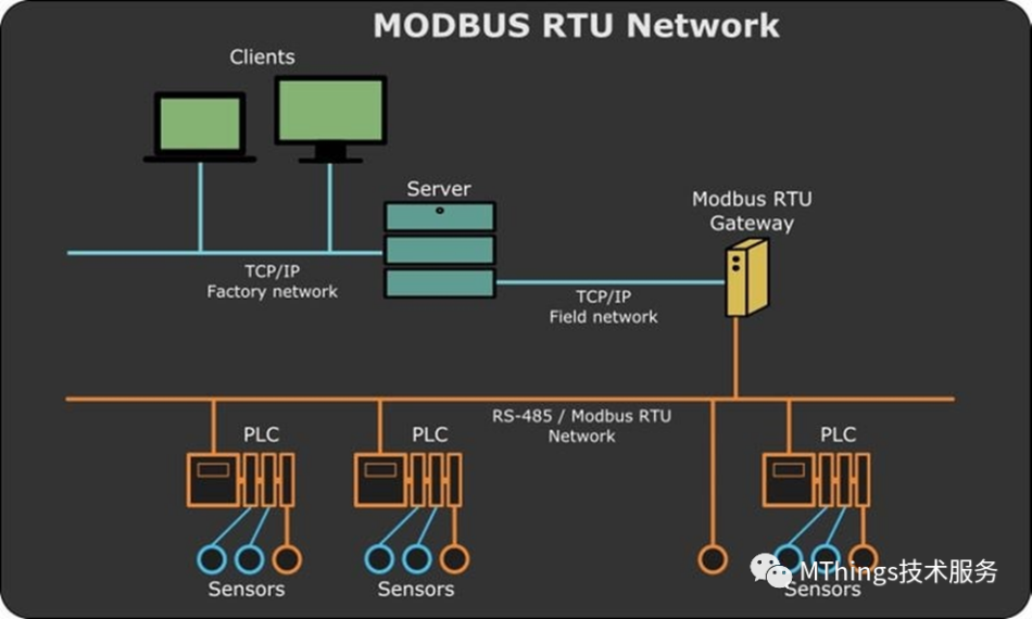
1. Correct terminal wiring
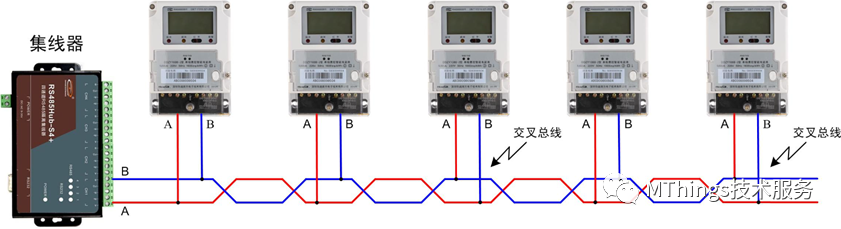
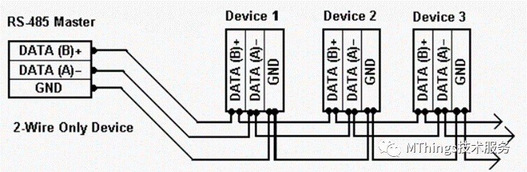
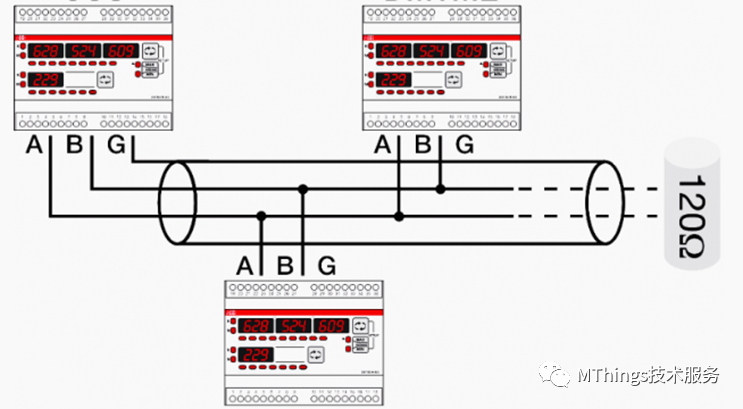
Each Modbus device shall provide at least one communication port and two connection terminals. For convenience, it is indicated as A and B. In these two terminals, connect the communication cable so that all devices participating in communication are connected in parallel. All "A" terminals must be connected together, and all "B" terminals must be connected separately.
Note:If the AB terminal is reversed, it not only affects individual devices, but may also cause abnormal communication in the entire daisy chain network.
Suggestion:During on-site wiring construction, distinguish the cable colors on terminals A and B, for example, use white communication cables uniformly for terminal A and blue communication cables uniformly for terminal B.
Both incoming and outgoing lines are allowed to be inserted into each terminal, and the main inlet and outlet terminals can be directly connected to the terminals of the instrument without the need to create branches. If only one cable can be inserted into each terminal, a three-way terminal must be used to create appropriate branches for each instrument to be connected.
2. Correct wiring between devices
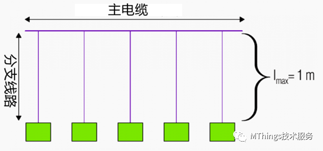
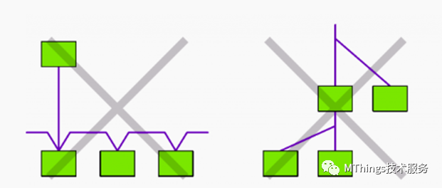
Modbus RS485 adopts a daisy chain bus connection, which differs from strong electric parallel circuits in that there are many requirements for the parallel connection of communication lines. The Modbus RS485 bus provides a main cable (backbone), and all devices must be connected to the main cable through branch lines and as short as possible.
Note:The length of branch lines shall not exceed 1200 meters. Long branch lines will cause signal reflection and interference, resulting in the inability to transmit and receive communication data normally.
Wrong bus wiring method:
3. Maximum communication distance and maximum number of devices
The recommended length of the main cable in design and construction should not exceed 700 meters, excluding the length of branch lines. The length limit of the main cable under different communication baud rates is as follows:
| Baud rate (bps) | Effective communication distance (meters) |
| 150 - 9600 | 1220 |
| 19200 | 975 |
| 38400 | 914 |
| 57600 | 701 |
| 115200 | 488 |
Ps:Based on 24 AWG twisted pair shielded wire, 0.085 ohms/meter, 41pF/meter between wires, and 72pF/meter from wire to shielding layer.
It is recommended that the total number of devices connected to the main cable during design and construction should not exceed 32, including the host node. The maximum number of load devices in the bus mainly depends on the chip type of the RS485 converter and is related to the quality of the communication cable used. The more device nodes, the farther the transmission distance, and the more harsh the electromagnetic environment, the higher the requirements for the selected cables.
The question of how many devices can be controlled by a serial port in RS485 communication is determined by the electrical and protocol characteristics of the RS485 network. The so-called electrical characteristics refer to ensuring that the characteristic impedance in the RS485 network is within the allowable range (120 ohms). The more devices connected, the smaller the characteristic impedance. When there are many device nodes on the bus, a terminal resistance of 120 ohms should be added at the end of the bus.
4. Proper use of repeaters
When the effective distance requirement for data transmission exceeds the design requirements, or when there are a large number of devices, signal repeaters can be added to avoid excessive signal attenuation.
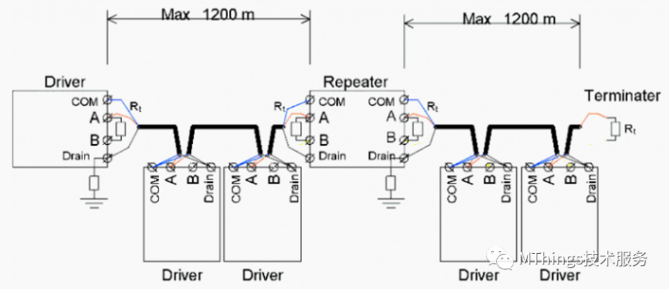
Each repeater will connect two adjacent main cables in series, and it is recommended not to deploy more than three repeaters on the same bus, otherwise significant data transmission delays will occur.
5. Selection of communication cables
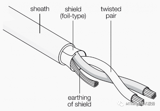
Modbus RS485 should use shielded twisted pair cables. The wire is composed of two twisted wires, and the shielding layer can be a woven metal mesh or wrapped foil.
6. Shielding layer grounding
The cable shielding layer must have a single point grounding, which can be completed at one end of the main cable.
7. Set matching resistor
When the communication distance is long and there are many device nodes, to avoid signal reflection, a 120 ohm matching resistor must be installed at the end of the main cable. This requirement is not mandatory and mainly depends on the communication situation after on-site wiring. Therefore, a matching resistor installation position should be reserved during the wiring process.
The article is translated from: https://mp.weixin.qq.com/s/HWS82XC5jolMOTDAdFmV1w


Leave a Reply