
Modbus Serial Line Communication Practical Guide: Ultimate Configuration Manual for RS-485 Wiring, Terminating Resistors, and Bias Resistors
Keywords:RS-485 Wiring, Modbus Serial Line, Terminating Resistor 120Ω, Bias Resistor, RS-485 Troubleshooting, Daisy Chain Topology
In Modbus communication failures, at least 60% of the problems arise at the physical layer - incorrect wiring, missing terminating resistors, improper configuration of bias resistors, and poor grounding. However, most Modbus tutorials skip directly to the protocol message level, glossing over the most troublesome issues for engineers such as "how to wire", "how to select resistors", and "why communication is intermittent".
This article, from an electrician's perspective, uses practical language that you can directly apply on-site to explain every detail of RS-485 wiring. After reading this article, you will be able to independently troubleshoot and solve 95% of Modbus serial line communication problems.
1. RS-485 Electrical Basics: The Magic of Differential Signaling
1.1 Why Differential Signaling?
RS-232 uses single-ended signaling (one signal line + one ground line), with signal voltage referenced to the ground line. When the interference noise on the ground line reaches a certain amplitude, the receiving end cannot correctly determine the logic level. This is the fundamental reason why RS-232 has a short communication distance (usually ≤15 meters) and low speed (≤115200bps).
RS-485 uses differential signaling: it transmits signals that are in phase opposition using two wires (A and B). The receiving end measures the voltage difference between the A and B lines, and the common-mode noise produces interference amplitudes that are essentially the same on both lines, which cancel each other out when subtracted. This is the core reason why RS-485 can reliably communicate over a distance of 1200 meters.
差分信号原理示意:

发送端         传输线         接收端
  A ────→ 波形: ───╲___╱─── → A
                        ↓
              差值 = (VA - VB) = 逻辑判定依据
                        ↑
  B ────→ 波形: ___╱‾‾‾╲___ → B

噪声同时叠加在 A 和 B 上 → 相减后噪声被消除
1.2 Quick reference for RS-485 electrical parameters
| Parameter | Typical Value | Description |
|---|---|---|
| Differential Output Voltage (Loaded) | ≥ 1.5V | When connected to a 54Ω load |
| Differential Output Voltage (Unloaded) | ≤ 5V | |
| Receiver Input Sensitivity | ±200mV | Minimum Recognizable Differential Voltage |
| Common Mode Voltage Range | -7V ~ +12V | Maximum voltage range of A/B to ground |
| Short-circuit current | ≤ 250mA | Maximum current of A/B during short circuit |
| Characteristic impedance | 120Ω | Characteristic impedance of standard twisted pair |
II. Wiring Practice: Daisy Chain vs Star Topology
2.1 Daisy Chain Topology (Correct Practice)
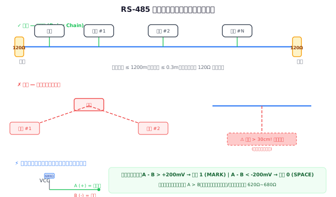
The Daisy Chain is the only recommended topology for RS-485. All devices are connected in series on a single bus without any branches:
正确 ✅ 菊花链拓扑:

 主站 ─── 从站1 ─── 从站2 ─── 从站3 ─── 终端电阻
  │         │         │         │
  └─A───────┴─A───────┴─A───────┴─A
  └─B───────┴─B───────┴─B───────┴─B

每段支线长度 ≤ 30cm(越短越好)
2.2 Star Topology (Common Mistake)
In electrical work sites, for ease of wiring, many people unconsciously connect RS-485 in a star topology:
错误 ❌ 星型拓扑:

         ┌──── 从站1
         │
 主站 ───┼──── 从站2
         │
         └──── 从站3

问题:每条分支的阻抗不连续,信号在分叉处产生严重反射
Consequences of star topology:
- Severe signal reflection, resulting in inconsistent communication
- May barely work at low baud rates (≤9600bps), but immediately crashes when increased
- Some devices communicate normally, while others do not respond at all
What if the site has already been wired in a star topology?
- Use an RS-485 hub (HUB) - electrically isolate each branch of the star topology
- Use an RS-485 repeater - split one bus into multiple independent bus segments
- Rewire (the most thorough but highest cost)
2.3 Correct wiring method for A/B wires
The biggest pain point in the industry: inconsistent identification of A/B wires!
Different manufacturers have different identification methods for RS-485 A/B wires, and some are even completely opposite. Here is a comparison table of common identification methods:
| Manufacturer | Identification method | Line with high idle state |
|---|---|---|
| Most domestic devices | A / B | A |
| Schneider, Siemens | D1 / D0 | D1 |
| Some imported devices | + / - | + |
| Certain special devices | A is marked as the negative (-) terminal | B! (Contrary to most) |
Universal Verification Method:Use a multimeter to measure the voltage between A and B of the device in an idle state. If A is positive relative to B (approximately +0.2V to +5V), then both wires are properly connected (with the same identification interconnected). If the reading is negative, then the A/B identification of a certain device is reversed.
III. Terminating Resistor: Why is it needed, and how to choose it?
3.1 Physical Principle of Signal Reflection
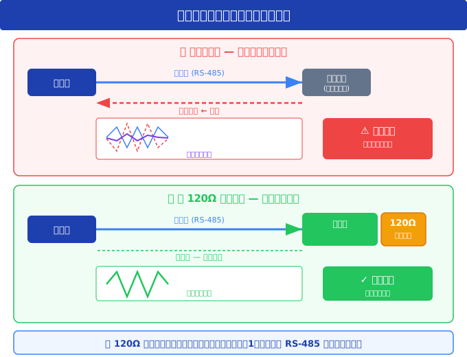
When an electrical signal propagates along a transmission line to the end, if the impedance of the end does not match the characteristic impedance of the transmission line, a portion of the signal energy will be reflected back, superimposing on the original signal. The reflected signal can cause waveform distortion, and in severe cases, the receiving end cannot correctly identify the logic level.
The role of terminating resistor:Place a resistor equal to the characteristic impedance (120Ω) in parallel at both ends of the bus to absorb the signal energy arriving at the end and eliminate reflection.
3.2 Terminating Resistor Configuration Rules
| Scenario | Terminating Resistor Configuration |
|---|---|
| Short distance (<50m), low rate (≤9600bps) | No terminating resistor is required (although it is still recommended in practice) |
| Medium distance (50m~300m) | Add 120Ω at both ends of the bus |
| Long distance (>300m) or high speed (>19200bps) | Add 120Ω + bias resistor at both ends of the bus |
| The master station is located in the middle of the bus | Add 120Ω at both ends of the bus (the master station itself does not need to add) |
Important:Terminal resistors should only be added at the farthest ends of the bus, do not add them at every node in the middle! Adding too many terminal resistors will cause the bus load to be too heavy, and the signal amplitude will be severely reduced.
3.3 Verify terminal resistors with a multimeter
Disconnect all device power supplies, and use a multimeter to measure the resistance between A and B:
- If there is a 120Ω terminal resistor at each end → the measured value should be approximately 60Ω (two 120Ω resistors in parallel)
- If there is no terminal resistor → the measured value should be high resistance (>1kΩ)
- If there is only one terminal resistor → the measured value should be approximately 120Ω
IV. Bias Resistor: Preventing Bus "Floating"
4.1 Why Bias?
When all devices on the bus are in a receiving state (i.e., no device is transmitting), the differential voltage between A and B approaches 0V. For an RS-485 receiver with a sensitivity of ±200mV, this ambiguous state may lead to:
- Random flipping of the receiver output, generating "false data"
- The UART of the slave receives a large number of garbage bytes, resulting in frame errors
- Communication indicator lights flicker irregularly
The bias resistor (Fail-Safe Bias) ensures that the bus maintains a definite logic 1 state in an idle state by applying a definite bias voltage on the A and B lines.
4.2 Calculation Method for Bias Resistor
The standard bias circuit pulls the A line up to VCC (usually +5V) through a resistor and pulls the B line down to GND through an equivalent resistor:
偏置电路示意图:

VCC (+5V)
  │
  ├── Rb ──┬── A 线 ──── Rt(120Ω) ──── B 线 ──┬── Rb ──┤
           │                                  │
        设备接口                              GND

Rb = 偏置电阻, Rt = 终端电阻
Selection of Bias Resistor Value:
- Target bias voltage ≥ 200mV (minimum recognition voltage of the receiver)
- Recommended bias voltage: 250mV ~ 300mV, with a margin
- Common configuration: 1 terminal resistor + 2 680Ω bias resistors
- If two terminal resistors (60Ω in parallel): bias resistor value should be 560Ω ~ 680Ω
Calculation formula (when both ends have terminal resistors):
Vab = VCC × Rt / (Rt + 2 × Rb)

其中:
  VCC = 5V(典型偏置电源电压)
  Rt  = 60Ω(两个 120Ω 终端电阻并联)
  Vab ≥ 0.2V(目标偏置电压)

解出: Rb ≤ 720Ω

实际取标准值 560Ω 或 680Ω
4.3 When is it necessary to add a bias resistor?
Scenarios where a bias resistor must be added:
- The bus has been installed with terminal resistors (terminal resistors will make the idle voltage approach zero)
- There are a large number of devices on the bus (>10), and the cumulative effect of receiver leakage current affects the bias
- Long-distance communication (>300m) reduces noise tolerance
Scenarios where a bias resistor can be omitted:
- No terminal resistors are installed (devices usually have weak internal bias)
- Most devices on the bus have built-in bias functionality
V. Grounding: A Neglected Key Link
RS-485 is a differential signal, theoretically not requiring a common ground. However, in practical engineering, grounding issues remain the third leading cause of communication instability (after wiring errors and terminal resistance issues).
5.1 Common Mode Voltage Exceedance
When there is a significant potential difference between the "grounds" of two devices, the voltage of the A and B lines relative to the receiving terminal ground may exceed the common mode range (-7V ~ +12V) of the RS-485 transceiver, resulting in damage or abnormal operation of the transceiver. This is why, even for differential signals, it is still recommended to use a signal ground (SG) to connect the common terminals of all devices.
Grounding Recommendations:
- Try to use twisted-pair cables with shielding layers (such as Belden 3105A)
- Single-point grounding of the shielding layer (usually at the master station end) to avoid ground loops
- If a third wire is used as a signal ground (SG), connect it to the local ground through a 100Ω resistor at each device
5.2 The Importance of Isolation
In industrial sites, it is strongly recommended to use RS-485 interfaces with optoelectronic or magnetic isolation. Isolation can:
- Eliminate common mode voltage issues caused by ground potential differences
- Prevent lightning strikes and surges from damaging equipment through communication lines
- 50Hz power frequency interference caused by blocking the grounding loop
VI. Cable Selection Guide
| Parameters | Recommended Values | Descriptions |
|---|---|---|
| Cable Type | Characteristic Impedance 120Ω twisted-pair shielded cable | such as Belden 3105A, 9841 |
| Wire Diameter | 24AWG (0.2mm²) or thicker | Choose a thicker wire diameter for long distances |
| Shielding Layer | Double shielding with aluminum foil + braided mesh | Essential in strong interference environments |
| Number of pairs | At least 1 pair (A/B) + 1 ground wire | Recommended: 1.5 pairs or 2 pairs |
| Recommended brands | Belden, LAPP, Nexans | Domestic brands: Hengtong, Zhongtian |
Wires to avoid:
- Ordinary parallel wires (non-twisted pair) - lack impedance control, resulting in poor signal quality
- One pair from network cables (100Ω characteristic impedance) - not fully matched with 120Ω, unreliable for long distances
- Power cables - severe strong electrical interference, and safety concerns
VII. Debugging Tools and Troubleshooting SOP
7.1 Essential Debugging Tools
| Tools | Purpose | Recommended Model |
|---|---|---|
| Multimeter | Measure voltage, resistance, continuity | Fluke 17B+ |
| USB to RS-485 | Connect to computer for debugging | FTDI chip solution (such as UT-890A) |
| Modbus debugging software | Send and receive Modbus messages | Modbus Poll, QModMaster |
| Oscilloscope (optional) | Observe signal waveform, reflection | Rigol DS1054Z |
| RS-485 tester | Dedicated bus analysis | Witte 485-Tester |
7.2 Troubleshooting SOP (Standard Operating Procedure)
When there is a problem with Modbus RTU communication, please troubleshoot in the following order:
- Power off and measure resistance:Use a multimeter to measure the resistance between A and B, which should be approximately 60Ω (with terminal resistance) or high resistance (without terminal resistance)
- Power on and measure voltage:In idle state, A to GND should be > B to GND (idle state is logic 1)
- Check topology:Confirm it is a daisy chain with no star branches
- Single device test:Connect only one slave station (with terminal resistance added), and test with Modbus Poll
- Add one by one:Add one slave station at a time, confirm communication is normal before adding the next one
- Baud rate scanning:If you are not sure about the device baud rate, start with 9600 and try step by step
VIII. Frequently Asked Questions (FAQ)
Q1: Must the terminal resistance be precisely 120Ω?
Precise matching is not required. Using 120Ω ± 5% (114~126Ω) is sufficient. A power of 1/4W is adequate. The key is to add, rather than being precise to the exact ohms.
Q2: What should I do if communication deteriorates after adding a terminating resistor?
This may be because a terminating resistor was added without adding a bias resistor. The terminating resistor pulls the idle voltage down into the receiver's ambiguity zone. The solution is to install a bias resistor (such as 2 × 680Ω) simultaneously.
Q3: What is the maximum length of a branch line for each device?
Theoretically, the branch line length should satisfy: branch line delay < 1/4 of signal rise time. For a typical RS-485 driver (with a rise time of about 100ns), the branch line length should be ≤ 5 meters. However, in practice, it is recommended to keep the branch line within 30 centimeters.
Q4: Is it normal for the communication light to flicker when the device is idle?
No, it is not normal. If the communication indicator light flickers when idle, it indicates that the receiver is outputting random data. This is usually due to the lack of a bias resistor, leading to an uncertain bus state. Installing a bias resistor can resolve the issue.
IX. Summary
RS-485 wiring is the cornerstone of Modbus communication reliability. Remembering these three golden rules can avoid most on-site problems:
- Use only a daisy chain topology-- Do not have any branches
- Terminate both ends with a terminating resistor (120Ω) and add a bias resistor at one location (2 × 680Ω)——Both are indispensable
- A connects to A, B connects to B——After power-on, use a multimeter to verify that the voltage from A to B is positive
Once you have eliminated these electrical issues one by one, and then look at the protocol messages, you will find that Modbus communication can be so stable.
Related Reading:In-depth Comparison between Modbus RTU and TCP | Complete Manual of Modbus Exception Response Codes | Modbus CRC Checking Principle and Programming Implementation


Leave a Reply