
Description
Product Introduction1.1Product Overview
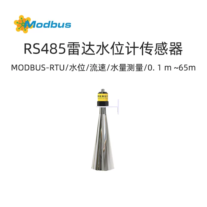
The radar water level gauge series products refer to frequency modulated continuous wave (FMCW) radar products operating at 76-81GHz. The maximum range of the product can reach 70m, with a blind spot within 10cm. Due to its higher operating frequency, larger bandwidth, and higher measurement accuracy. The product provides a fixed method for the bracket, which can be used in conjunction with our company's water and rain situation poles and mainframe.
1.2 Functional Features
- Based on our self-developed CMOS millimeter wave RF chip, we achieve a more compact RF architecture, higher signal-to-noise ratio, and smaller blind spots.
- has a large working bandwidth, which enables the product to have higher measurement resolution and accuracy. The narrowest antenna beam angle of
- is 6 °, and the interference in the installation environment has less impact on the instrument, making installation more convenient.
- Integrated lens design, compact size, easy to install
- Low power consumption, long lifespan.
1.3 Main technical specifications
| Power supply | DC10-30V |
| Maximum power consumption | 0.2W |
| Transmission frequency | 76GHz~81GHz |
| Measurement range | 0.1 m~65m |
| Measurement accuracy | ± 1mm |
| Beam angle | 6 ° |
| Operating temperature | -40 ℃~+60 ℃, 0% RH~95% RH (non condensing) |
| Communication protocol | RS485 output |
| Protection level | IP67 |
Installation and use
2.1Equipment pre installation inspection
Equipment list:
2.2 Installation steps instructions
Two points to note during installation:Ensure that the water level gauge is installed perpendicular to the water surface. Tilting it will weaken the amplitude of the received signal and affect normal distance measurement.
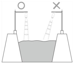 Diagram of Instrument Installation LocationEnsure that there are no interfering objects within the beam range, such as riverbanks.
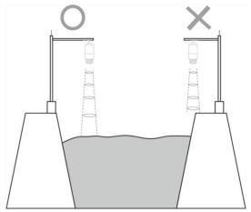 Diagram of Instrument Installation Location
2.3 Power supply and485 Signal wiring instructions
Wide voltage power supply can input 10-30V. When wiring the 485 signal line, be careful not to connect the A/B wires in reverse, and ensure that the addresses of multiple devices on the bus do not conflict.Please note that the power supply voltage of the device is within the range of 10V-30V, and it is recommended to use 12V power supply.
2.4 Specific model wiring
Wiring Instructions
| 485 Type | ||
| power supply | red | VCC |
| black | GND | |
| Output | green | 485A |
| yellow | 485B | |
3.1 Software selection
Please contact our company staff for specific information.
3.2Parameter Settings
①. Select the correct COM port (check the COM port in "My Computer - Properties - Device Manager - Ports")
4. Communication Protocol
4.1 Basic communication parameters
| Encoding | 8-bit binary |
| data bit | 8 digits |
| Parity check bit | None |
| Stop bit | 1-bit |
| Error check | CRC (redundant cyclic code) |
| Baud rate | 9600 bit/s |
4.2Data frame format definition
Adopting ModBus RTU communication protocol, the format is as follows:Host query frame structure:
| address code | Function code | Register starting address | Register length | Check code low byte | Check code high byte |
| 1 byte | 1 byte | 2 bytes | 2 bytes | 1 byte | 1 byte |
Slave response frame structure:
| Address Code | Function Code | Effective Byte Count | Data Area 1 | Data Area 2 | Data Area N | Check Code Low Byte | Check Code High Byte |
| 1 Byte | 1 Byte | 1 Byte | 2 bytes | 2-byte | 2-byte | 1-byte | 1-byte |
4.3 Register Address
| Register Address | Content | Operation | Function Code | Definition Explanation |
| 0000 H | Empty height value (cm) | Read only | 03 | Read empty height, unit cm |
| 0001 H | Empty height value (mm) | Read only | 03 | Read empty height, unit mm |
| 0002 H | Liquid level high (cm) | Read only | 03 | Read empty height, unit cm |
| 0003 H | High liquid level (mm) | Read only | 03 | Read high liquid level, unit mm |
4.4Communication protocol example and explanation
Read device address0x01 Device0 register empty high value
| address code | function code | starting address | Data length | Check code low byte | Check code high byte |
| 0x01 | 0x03 | 0x00 0x00 | 0x00 0x01 | 0x84 | 0x0A |
| Address code | Function code | Return the number of valid bytes | Data area | Check code low byte | Check code high byte |
| 0x01 | 0x03 | 0x02 | 0x00 0x64 | 0xB9 | 0xAF |
| Address code | Function code | Return the number of valid bytes | Data area | Check code low byte | Check code high byte |
| 0x01 | 0x03 | 0x02 | 0x03 0xE8 | 0xB8 | 0xFA |
5. Common problems and solutions
5.1Device cannot connect toPLC or computer
Possible reasons: