
Practical Guide to Modbus Programming in Mainstream PLCs (Siemens, Mitsubishi, Delta, and Inovance Full Series)
In the field of industrial automation,Modbus PLC programmingis a core skill that every automation engineer must master. Whether it's the dedicated communication instructions for Siemens S7-1200/1500, the ADPRW instructions for Mitsubishi FX5U, the MODRW instructions for Delta DVP series, or the free-port programming for Inovance H3U, different brands of PLCs have significant differences in the implementation of Modbus communication. As an important part of themodbus.cnseries of tutorials, this article will systematically compare the Modbus programming methods of the four major mainstream PLC brands, providing complete ladder diagram examples and address mapping relationships to help engineers quickly master the development of cross-brand PLC Modbus communication.
Overview of Modbus Implementation Comparison Across Brands
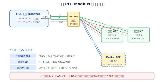
Before delving into specific programming, let's first understand a key difference: the support methods for the Modbus protocol by different brands of PLCs are divided into two categories: "dedicated instructions" and "free-port programming". The dedicated instruction method involves the PLC manufacturer encapsulating the Modbus protocol stack, and engineers only need to call the instructions and configure parameters to complete communication; while the free-port programming method requires engineers to manually construct Modbus packet frames and implement the protocol by sending and receiving byte by byte through the serial port. Both methods have their advantages and disadvantages, and the table below provides an intuitive comparison.
| Brand/Series | Implementation Method | Core Instruction/Mechanism | Development Difficulty | Flexibility |
|---|---|---|---|---|
| Siemens S7-1200/1500 | Special Instructions | MB_COMM_LOAD / MB_MASTER / MB_SLAVE | Low | In the middle |
| Mitsubishi FX5U | Special Instructions | ADPRW | Low | In the middle |
| Mitsubishi FX3U | Special Instructions | ADPRW (requires adapter) | In the middle | In the middle |
| Delta DVP Series | Special Instructions | MODRW | Low | In the middle |
| Delta AS Series | Special instructions | MODRW / M_MODRW | Low | High |
| Inovance H3U | Free port programming | RS instructions + CRC check | High | High |
| Inovance AM600 | Special instructions | Modbus function block | Low | In the middle |
As can be seen from the table above,Siemens Modbus RTU And and Mitsubishi Modbus communicationall adopt special instruction schemes, with a relatively low development threshold;The H3U series in Inovance Modbus programmingrequires free-port programming, which demands a higher level of understanding of the protocol from engineers.The MODRW instruction of Delta PLC Modbusis renowned for its simplicity and ease of use.
Detailed explanation of Siemens S7-1200/1500 Modbus programming
The Siemens TIA Portal platform provides a complete Modbus communication library for the S7-1200 and S7-1500 series PLCs, including three core instructions: MB_COMM_LOAD (communication initialization), MB_MASTER (master communication), and MB_SLAVE (slave communication). These instructions are located under the "Communication" instruction group, specifically in the "Other" → "Modbus" path.
MB_COMM_LOAD — initialization of the communication module
Before using any Modbus communication, the MB_COMM_LOAD instruction must be called to configure the communication module. The function of this instruction is similar to setting basic parameters such as baud rate, parity bit, data bits, and stop bits for serial ports, while specifying the Modbus working mode (RTU or ASCII).
| Parameter | Data type | Description | Typical value |
|---|---|---|---|
| REQ | Bool | Rising edge trigger configuration | M0.0 |
| PORT | UInt | Communication module hardware identifier | 269 (CM1241 RS485) |
| BAUD | UInt | Baud rate | 9600 / 19200 / 38400 / 115200 |
| PARITY | UInt | Parity bit: 0=None 1=Odd 2=Even | 2 (Even parity) |
| FLOW_CTRL | UInt | Flow control: 0=None 1=RTS/CTS | 0 |
| RTS_ON_DLY | UInt | RTS ON Delay (ms) | 0 |
| RTS_OFF_DLY | UInt | RTS OFF Delay (ms) | 0 |
| RESP_TO | UInt | Response Timeout (ms) | 1000 |
| MB_DB | Variant | Background Data Block of MB_MASTER/SLAVE | DB Number of Corresponding Command |
| DONE | Bool | Configuration Complete Flag | — |
| ERROR | Bool | Error Flag | — |
| STATUS | Word | Status Code (16#0000=No Error) | — |
MB_MASTER — Modbus Master Communication Command
The MB_MASTER instruction enables the S7-1200/1500 to act as a Modbus RTU master station, sending read and write requests to slave devices. This instruction supports function codes 01 (read coil), 02 (read discrete input), 03 (read hold register), 04 (read input register), 05 (write single coil), 06 (write single register), 15 (write multiple coils), and 16 (write multiple registers).
// MB_MASTER 梯形图参数说明(SCL 表示)
"MB_MASTER_DB"(
    REQ    := #Start_Read,        // 上升沿触发
    MB_ADDR:= 1,                  // 从站地址(1-247)
    MODE   := 0,                  // 0=读 1=写
    DATA_ADDR := 40001,           // 从站数据起始地址
    DATA_LEN  := 10,              // 数据长度(字数)
    DATA_PTR  := P#DB1.DBX0.0 WORD 10  // 本地数据存储区指针
);

// 常见模式:
// MODE=0, DATA_ADDR=40001 → 功能码 03 读保持寄存器
// MODE=1, DATA_ADDR=40001 → 功能码 06/16 写保持寄存器
MB_SLAVE — Modbus slave communication instruction
The MB_SLAVE instruction enables the S7-1200/1500 to act as a Modbus RTU slave station, responding to read and write requests from the master station. This instruction allows the master station to access specific data areas (coils, discrete inputs, input registers, hold registers) within the PLC.
// MB_SLAVE 梯形图参数说明(SCL 表示)
"MB_SLAVE_DB"(
    MB_ADDR    := 1,              // 本从站地址
    MB_HOLD_REG := P#DB2.DBX0.0 WORD 100  // 保持寄存器映射区
);
Complete ladder diagram example: reading temperature and humidity sensor
Below is a complete example of a Siemens S7-1200 program for reading a Modbus temperature and humidity sensor. The sensor slave address is 1, and the temperature and humidity are stored in hold registers 40001 and 40002, respectively, with a baud rate of 9600 and even parity.
网络 1:初始化通信模块(首次扫描调用)
┌──────────────────────────────┐
│  M0.0    MB_COMM_LOAD        │
│──┤P├────┤EN              DONE├──M0.1
│         │PORT:  269   ERROR├──M0.2
│         │BAUD:  9600  STATUS├──MW2
│         │PARITY:2           │
│         │FLOW_CTRL:0        │
│         │RESP_TO:1000       │
│         │MB_DB:MB_MASTER_DB │
└──────────────────────────────┘

网络 2:周期性读取传感器数据(每 500ms)
┌──────────────────────────────┐
│  M0.5    MB_MASTER           │
│──┤P├────┤EN              DONE├──M1.1
│         │MB_ADDR:1    ERROR├──M1.2
│         │MODE:0       STATUS├──MW4
│         │DATA_ADDR:40001     │
│         │DATA_LEN:2          │
│         │DATA_PTR:P#DB3.DBX0.0 WORD 2
└──────────────────────────────┘
// 读取结果:
// DB3.DBW0 = 温度值(需要除以 10 得到实际温度)
// DB3.DBW2 = 湿度值(需要除以 10 得到实际湿度)
For more detailed Modbus configuration on the Siemens PLC platform, please refer to the relevant article on Siemens communication module hardware selection onmodbus.cn. You can also check out ourSiemens Modbus RTU complete configuration tutorial.
Mitsubishi FX5U Modbus programming details
Mitsubishi Modbus communicationis implemented on the FX5U series through the ADPRW dedicated instruction, which represents a qualitative leap compared to the solution requiring additional adapters in the FX3U era. The built-in RS-485 port of the FX5U directly supports the Modbus RTU protocol, eliminating the need for additional hardware investment. The powerful aspect of the ADPRW instruction is that it can specify Modbus function codes and send and receive data with a single instruction.
ADPRW instruction details
| Operating number | Description | Setting range | Example |
|---|---|---|---|
| S1 | Slave address | H1-HF7 (1-247) | H1 |
| S2 | Function code | H1-H6, HF, H10 | H3 (read hold register) |
| S3 | Modbus address | H0-HFFFF | H0 (corresponding to 40001) |
| S4 | Number of data points | H1-H7D0 (words) | K2 |
| D1 | Starting soft component for sending/receiving data | Bit/word soft component | D100 |
When executing the ADPRW instruction, the PLC automatically constructs a Modbus frame, calculates the CRC check code, sends the frame, and waits for a reply from the slave station. For write operations (function codes H6/H10), the soft component area specified by D1 stores the data to be sent; for read operations (function codes H1-H4), the soft component area specified by D1 stores the received data.
Key Considerations for ADPRW
- Address Offset Rule: Modbus protocol addresses are numbered starting from 0, but addresses in the documentation (such as 40001) start from 1. In the S3 operand of ADPRW, the hold register starts from H0 corresponding to 40001, and the coil starts from H0 corresponding to 00001.
- Function code H3 (read hold register) can read up to 125 words (H7D) at a time.
- Function code H10 (write multiple registers) can write up to 123 words (H7B) at a time.
- The ADPRW instruction is an execution-complete instruction that requires multiple consecutive scan cycles to complete a single communication.
- Communication status must be determined through special relay SM and special register SD.
Ladder Diagram Example: FX5U reading frequency converter parameters
// 网络 1:通信参数设置(通过 PLC 参数配置,无需梯形图)
// 通道 1(CH1):内置 RS-485
// 协议:Modbus RTU
// 波特率:19200 bps
// 数据位:8
// 停止位:1
// 校验:偶校验

// 网络 2:读取变频器运行频率和输出电流
┌──────────────────────────────┐
│ M0               [ADPRW    ]│
│──┤├──────────────┤S1: H1    │  // 从站地址 1
│                  │S2: H3    │  // 功能码:读保持寄存器
│                  │S3: H100  │  // 起始地址:40101(频率)
│                  │S4: K2    │  // 读取 2 个字
│                  │D1: D100  │  // 数据存储到 D100-D101
└──────────────────────────────┘

// 网络 3:数据处理
// D100 = 运行频率(单位 0.01Hz,需要除以 100)
// D101 = 输出电流(单位 0.1A,需要除以 10)

// 网络 4:写入运行频率设定
┌──────────────────────────────┐
│ M1               [ADPRW    ]│
│──┤├──────────────┤S1: H1    │  // 从站地址 1
│                  │S2: H6    │  // 功能码:写单寄存器
│                  │S3: H200  │  // 目标地址:40201
│                  │S4: K0    │  // 写操作时忽略
│                  │D1: D200  │  // 写入的数据
└──────────────────────────────┘
Mitsubishi FX5U's Modbus communication speed can reach 115200 bps, performing well in multi-station polling scenarios. For more in-depth information on Mitsubishi Modbus communication, please refer to the complete tutorial on Mitsubishi Modbus communication onmodbus.cnonand detailed explanations of Delta DVP/AS series Modbus programming on.
Detailed Explanation of Delta DVP/AS Series Modbus Programming
Delta PLC Modbuscommunication is elegantly implemented on the DVP and AS series.The MODRW instructionis the core instruction for Delta PLCs to perform Modbus communication, with its design philosophy being "one instruction solves all problems" - whether it's reading or writing, coils or registers, it's all done through this instruction. The AS series even provides an enhanced version of the M_MODRW instruction, supporting more function codes.
MODRW instruction parameter description
| Parameter | Meaning | DVP series | AS series |
|---|---|---|---|
| S | Online device address | K1-K254 | K1-K254 |
| S1 | Function Code | K1/K2/K3/K4/K5/K6/K15/K16 | Ditto + Extension |
| S2 | Target Device Address | 0-9999 | 0-65535 |
| S3 | Data Length | 1-127 | 1-200 |
| D | Local Data Starting Register | D Register | D Register |
Ladder Diagram Example: Delta DVP Reading Smart Meter
// 台达 DVP-ES2 通过 COM2(RS-485)读取智能电表数据
// 电表从站地址:1,波特率 9600,无校验

// 网络:触发读取电表数据
┌───────────────────────────────┐
│ M1002             [ SET  M0 ]│  // 上电初始化
└───────────────────────────────┘

┌───────────────────────────────┐
│ M1013             [ MODRW   ]│  // 1 秒时钟脉冲触发
│──┤├───────────────┤S:  K1    │  // 从站地址 1
│                   │S1: K3    │  // 功能码:读保持寄存器
│                   │S2: K0    │  // 起始地址:040001
│                   │S3: K6    │  // 读取 6 个字
│                   │D:  D0    │  // 存储到 D0-D5
└───────────────────────────────┘

// 读取结果映射(某品牌智能电表):
// D0 = 电压(单位 0.1V → D0/10 = 实际电压)
// D1 = 电流(单位 0.01A → D1/100 = 实际电流)
// D2 = 有功功率(单位 1W)
// D3 = 无功功率(单位 1Var)
// D4 = 功率因数(单位 0.001 → D4/1000)
// D5 = 频率(单位 0.01Hz → D5/100)
Delta AS Series M_MODRW Enhanced Features
Delta AS Series PLCs (such as AS228T-A) provide M_MODRW instructions based on MODRW, with major enhancements including support for 32-bit data read and write, string transmission, bit writing, configurable communication timeout, and the ability to activate up to 8 communication instructions simultaneously. These enhancements give the AS Series a significant advantage in complex Modbus communication scenarios.
// 台达 AS 系列 M_MODRW 示例:读取 32 位电能累计值
┌───────────────────────────────────┐
│ M0                  [ M_MODRW   ]│
│──┤├────────────────┤S:  K1       │  // 从站地址
│                    │S1: K3       │  // 功能码:读寄存器
│                    │S2: K100     │  // 起始地址
│                    │S3: K2       │  // 读取 2 个字(含 32 位数据)
│                    │D:  D100     │  // 存储到 D100(低字)、D101(高字)
│                    │Mode: D200   │  // 模式设定
└───────────────────────────────────┘
Delta PLC's Modbus programming experience is among the best among domestic brands, and the simplicity of MODRW instructions significantly lowers the development threshold. For more technical details on Delta PLC Modbus communication, please visitmodbus.cnto refer tothe complete guide to Delta PLC Modbus communication.
and
Inovance H3U Modbus Freeport Programming ExplanationInovance Modbus programming
has unique features on the H3U series. Unlike other brands that provide dedicated Modbus instructions, H3U adopts a freeport communication method, requiring engineers to manually construct Modbus message frames and send them via RS instructions. Although this approach increases development difficulty, it gives engineers complete control over the communication process, making it very useful in non-standard protocols or special requirements scenarios.
Basic Principles of H3U Freeport Communication
Inovance H3U's serial communication is based on RS instructions (data send instructions) and RC instructions (data receive instructions). To implement Modbus RTU communication, it is necessary to manually construct message frames according to Modbus protocol specifications, including slave address, function code, data field, and CRC check code.
Implementation of CRC-16 Check Algorithm
// CRC-16 计算流程(Modbus RTU 标准算法)
// 输入:待校验数据存储在 D100-D105(6 字节,不含 CRC),字节数存于 D0
// 输出:CRC16 结果高字节存于 D200,低字节存于 D201
//
// 算法伪代码:
// 1. 预置 16 位 CRC 寄存器为 0xFFFF
// 2. 将第一个 8 位数据与 CRC 寄存器低字节异或,结果存入 CRC 寄存器
// 3. CRC 寄存器右移一位,最高位补 0
// 4. 移出位如果为 1,则 CRC 寄存器与 0xA001 异或
// 5. 重复步骤 3-4 共 8 次
// 6. 处理下一个字节,重复步骤 2-5
// 7. 所有字节处理完成后,CRC 寄存器的值即为 CRC16 校验码

// H3U 梯形图中的实现(使用循环指令)
// 注意:H3U 内置了 CRC 校验指令(CRC),可将校验码追加到发送数据末尾
// CRC D100 D106 K6
// 功能:对 D100 开始的 6 字节数据计算 CRC,结果存入 D106-D107
Complete Freeport Modbus RTU Master Example
// 汇川 H3U 自由口通信实现 Modbus RTU 主站
// 目标:读取从站地址 1 的保持寄存器 40001(2 个字)

// 网络 1:构建 Modbus 读保持寄存器报文
// 报文格式:[从站地址][功能码][起始地址高][起始地址低][字数高][字数低][CRC低][CRC高]
//
// 发送报文数据准备:
// D100 = H0103    // 从站地址 01 + 功能码 03
// D101 = H0000    // 起始地址 0000(对应 40001)
// D102 = H0002    // 读取 2 个字
// CRC 校验放入 D103

// 网络 2:配置串口参数(通过特殊寄存器)
// D8120 = H0C81   // 8位数据+偶校验+1停止位+9600bps
// M8161 = ON      // 8位数据处理模式

// 网络 3:发送数据
┌──────────────────────────────┐
│ M0               [ RS     ]│
│──┤├──────────────┤D100      │  // 发送起始寄存器
│                  │K8        │  // 发送 8 个字节(含 CRC)
│                  │D200      │  // 接收起始寄存器
│                  │K9        │  // 接收 9 个字节(含 CRC)
└──────────────────────────────┘

// 网络 4:接收数据处理
// D200 = 从站地址(应为 H01)
// D201 = 功能码(应为 H03)
// D202 = 字节数(应为 04)
// D203 = 第一字高字节
// D204 = 第一字低字节
// D205 = 第二字高字节
// D206 = 第二字低字节
// D207 = CRC 低字节
// D208 = CRC 高字节
The Inovance AM600 series (Codesys platform) offers a more modern Modbus communication method, implemented through dedicated function blocks, which is more similar to the Siemens solution. For a comparison of Modbus programming across the full range of Inovance PLCs, please refer tomodbus.cnforthe comprehensive guide to Modbus programming for the Inovance series.
and the comparison table of address mapping relationships across various brands
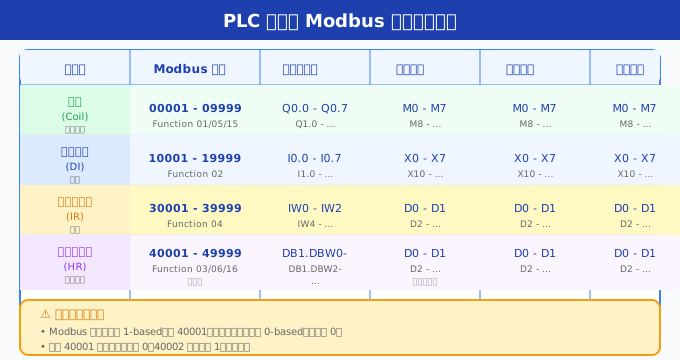
. One of the most error-prone aspects of Modbus communication is address mapping. PLCs from different brands have different representations for Modbus addresses, and there are also differences in address offset rules during programming. The following table summarizes the Modbus address mapping relationships for four major brands of PLCs, covering the core logic of over 2000 address mapping rules.
| Modbus address area | Protocol address | Siemens | Mitsubishi FX5U | Delta DVP | Inovance H3U |
|---|---|---|---|---|---|
| Coil 00001-09999 | 0-9998 | Q0.0-Qx.y | M0-Mx | M0-Mx | M0-Mx |
| Discrete Input 10001-19999 | 0-9998 | I0.0-Ix.y | X0-Xx | X0-Xx | X0-Xx |
| Input Register 30001-39999 | 0-9998 | IW0-IWx | SD Special Register | — | — |
| Hold Register 40001-49999 | 0-9998 | DBx.DBW0+ | D0-D7999 | D0-D9999 | D0-D7999 |
| Hold Register 400001-465535 | 0-65534 | Address Extension Required | D0-D7999 / R0+ | D0-D9999 / Extension | D0-D7999 / Extension |
Detailed Explanation of Address Offset Rules
Understanding address offsetting is the cornerstone of avoiding Modbus communication errors. The Modbus protocol defines addresses starting from 0, but application layer numbers (such as 40001) start from 1. Different brands of PLCs often use protocol addresses (0-based) in their instructions, which leads to a common "off-by-one" error.
| Scenario | Document address | Protocol address (used in instructions) | Offset |
|---|---|---|---|
| Read hold register 40001 | 40001 | 0x0000 (H0/K0) | -1 |
| Read hold register 40100 | 40100 | 0x0063 (H63/K99) | -1 |
| Read coil 00001 | 00001 | 0x0000 (H0/K0) | -1 |
| Write single register 40010 | 40010 | 0x0009 (H9/K9) | -1 |
| Read Input Register 30050 | 30050 | 0x0031 (H31/K49) | -1 |
Common Errors and Pitfalls
In practical engineering, debugging Modbus communication often consumes a significant amount of development time. The following are the most common errors and pitfalls identified by the author from hundreds of real-world projects, to help readers avoid detours.
1. Address Offset Error
This is one of the most common errors. The register address written in the device manual is "40001", but engineers often mistakenly fill in "1" or "40001" as the starting address in PLC instructions. The correct practice is to fill in "0" (protocol address = application address - 1). It is correct to fill in 40001 for the DATA_ADDR parameter of Siemens MB_MASTER (Siemens has encapsulated it), but the S3 parameter of Mitsubishi ADPRW should be filled in with H0, and the S2 parameter of Delta MODRW should be filled in with K0.
2. Byte Order (Endianness) Issue
When Modbus transmits 32-bit data (such as floating-point numbers, double-word integers), byte order issues can lead to data parsing errors. There are four common byte order combinations: Big-Endian byte order + Big-Endian word order (standard Modbus), Big-Endian byte order + Little-Endian word order, Little-Endian byte order + Big-Endian word order, and Little-Endian byte order + Little-Endian word order. Siemens PLCs use Big-Endian, while Mitsubishi and Delta use Little-Endian. When communicating across brands, byte order conversion must be considered.
3. Improper Timeout Setting
The standard for the inter-frame gap in Modbus RTU is 3.5 character times (approximately 3.6ms at 9600 bps).
4. Multi-master conflict
Modbus RTU is a single master protocol, and multiple masters are not allowed on the same bus. When an HMI touch screen and a PLC simultaneously access the same device as masters, a bus conflict occurs. The solution is to allow the HMI to indirectly access the device through the transparent transmission function of the PLC, or to use a Modbus TCP gateway for protocol conversion.
5. Inconsistent Communication Parameters
The baud rate, data bits, stop bits, and parity bits must be exactly the same as those of the slave. Note: Some devices claim to support "9600,8,N,1", but the actual data bits are 9 bits (8 data bits + 1 parity bit). Communication may fail due to a mismatch in byte length. It is recommended to use a Modbus debugging tool to confirm the actual communication parameters of the device.
Integration with SCADA System
Integrating PLCs with SCADA (Supervisory Control and Data Acquisition) systems via the Modbus protocol is one of the most common architectures in industrial automation. The following describes several typical integration methods and best practices.
Typical Integration Architecture
- Direct Connection Mode: SCADA connects directly to PLCs via Modbus RTU/TCP drivers. This is suitable for small systems (1-5 PLCs), with advantages of simple architecture and low latency; however, it has disadvantages of poor scalability and heavy burden on SCADA.
- OPC Server Relay Mode: PLC → OPC Server (such as Kepware, Matrikon) → SCADA. This is suitable for medium to large systems, with advantages of protocol decoupling and multi-client support; however, it increases the intermediate layer and maintenance costs.
- Data Gateway Mode: PLC → Modbus Data Gateway → SCADA/MES/ERP. This is suitable for enterprise-level systems, with advantages of unified data export, support for data caching and forwarding.
SCADA Configuration Essentials
When configuring the Modbus driver in SCADA, the most crucial step is to correctly set the register address mapping. Common SCADA platforms (such as WinCC, Kingview, LK, and Intouch) have different representations for Modbus addresses. For example, WinCC uses "4x0001" to represent the holding register, while Kingview uses the format "4-1". It is necessary to consult the Modbus driver documentation for each platform to confirm the address format before proceeding with the configuration.
Debugging Tips and Tool Recommendations
Efficient debugging is the key to successful Modbus communication development. The following are the tools and methodologies recommended by the author.
Essential Debugging Tools
| Tool Name | Type | Applicable Scenario | Recommended Reason |
|---|---|---|---|
| Modbus Poll | Desktop Software | Master Simulation | Intuitive interface, supports all function codes, and can perform scheduled polling |
| Modbus Slave | Desktop software | Slave simulation | Can be paired with Poll to simulate slave behavior |
| QModMaster | Open-source software | Master debugging | Free and open-source, supports RTU/TCP, cross-platform |
| ModScan | Desktop software | Master scanning | Batch scanning of slave registers, quickly establishing address mapping table |
| Serial port monitoring tool | Hardware/software | Bus monitoring | USB to 485 monitoring mode, recording raw messages |
| Wireshark | network packet capture | Modbus TCP analysis | supports Modbus TCP protocol parsing, with powerful functionality |
debugging methodology
- layered verification method: First confirm the physical layer (cable, terminal resistance, bias resistance) using an ammeter, then confirm the link layer (baud rate, parity) using Modbus Poll, and finally confirm the application layer (address, data format) using a PLC program.
- minimize testing: First perform communication testing using the simplest function code (03 read single register), confirm that the basic link is normal before testing complex functions.
- message recording method: Use a serial port monitoring tool to record complete messages, and manually analyze the message frames to locate problems. The Modbus message structure is simple, and problems can usually be identified at a glance.
- timeout progression methodStart debugging with a longer timeout (such as 3000ms), confirm normal communication, and gradually shorten the timeout to find the optimal value.
Comprehensive comparison of Modbus programming across four major brands
| Comparison dimensions | Siemens S7-1200/1500 | Mitsubishi FX5U | Delta AS series | Inovance H3U |
|---|---|---|---|---|
| Implementation methods | Dedicated instructions (library) | Dedicated instructions | Dedicated instructions | Freeport programming |
| Core Command | MB_COMM_LOAD/MB_MASTER/MB_SLAVE | ADPRW | MODRW/M_MODRW | RS+CRC |
| Programming Difficulty | ★★☆☆☆ | ★★☆☆☆ | ★★☆☆☆ | ★★★★☆ |
| Function Code Support | 01/02/03/04/05/06/15/16 | 01/02/03/04/05/06/15/16 | 01/02/03/04/05/06/15/16 | All (Manual) |
| Maximum Slave Count | 247 | 247 | 254 | 247 (Limited by Scan Cycle) |
| Maximum Data Volume per Transaction | 125 Words (Read)/123 Words (Write) | 125 Words (Read)/123 Words (Write) | 127 Words (Read)/123 Words (Write) | Unlimited (Manual) |
| Address Fault Tolerance | Automatic Offset Handling | Manual Offset Required (-1) | Requires manual offset (-1) | Requires manual offset (-1) |
| Multiple instructions in parallel | Not supported (needs to be queued) | Not supported (needs to be queued) | Supported (up to 8 instructions) | Manual management |
| Error diagnosis | STATUS Detailed status code | SM/SD register | Error flag bit | Manual judgment |
| TCP supports | MB_CLIENT/MB_SERVER | built-in Ethernet port | built-in Ethernet port | requires expansion module |
| floating-point support | requires byte order conversion | requires byte order conversion | requires byte order conversion | requires byte order conversion |
| development environment | TIA Portal | GX Works3 | ISPSoft/DIAStudio | AutoShop |
| Learning resources | Rich | Relatively rich | Medium | Less |
| Typical communication rate | 19200-115200 | 9600-115200 | 9600-115200 | 9600-19200 |
| Suitable scenario | Large system/standardized project | Small and medium-sized devices/rapid development | Domestic substitution/cost-effective priority | Customized demand/deep control |
FAQ Common problems
Q1: Does Modbus communication for Siemens S7-1200 require additional hardware modules?
Yes. The S7-1200 CPU typically only has an Ethernet port and a common RS-232/RS-485 interface (for some models). For Modbus RTU communication, it is recommended to use the CM1241 RS485 communication module (hardware ID 269) or the CB1241 signal board. For Modbus TCP communication, the CPU's built-in Ethernet port can support it without additional hardware. Similar to the S7-1200, the S7-1500 uses the CM PtP communication module.
Q2: How many devices can the Mitsubishi FX5U's ADPRW instruction read or write at a time?
The ADPRW instruction can only communicate with one slave device at a time. If multiple slaves need to be polled, multiple sets of ADPRW instructions need to be used in the program, ensuring that only one instruction is active at a time. The completion flag of the previous instruction can be used to trigger the next instruction, achieving serial polling. The typical multi-station polling cycle = number of stations × (request time + response time + inter-frame gap).
Q3: How to troubleshoot communication failures with Delta's MODRW instruction?
First, check whether the communication parameters are consistent (baud rate, parity bit, data bits, stop bits). Then confirm whether the A/B wires of RS-485 are reversed - this is the most common hardware issue. The communication error code can be viewed using the special registers built into Delta PLCs. Finally, ensure that the target address of the MODRW instruction matches the actual address of the slave. By default, Delta PLCs' COM2 port is in Modbus slave mode. If it needs to be used as a master, M1143 needs to be set to ON in the program.
Q4: How reliable is the implementation of Modbus through free port programming on Inovance H3U?
The free port Modbus communication of Inovance H3U is very reliable when the baud rate does not exceed 19200 bps.
Q5: How to solve the byte order issue of 32-bit floating-point numbers in Modbus communication?
32-bit floating-point numbers are transmitted in Modbus using two consecutive 16-bit registers, with the byte order determined by the device. Siemens and Schneider typically use Big-Endian byte order (with register N storing the high 16 bits and register N+1 storing the low 16 bits), while Mitsubishi, Delta, and Inovance typically use Little-Endian byte order (with register N storing the low 16 bits and register N+1 storing the high 16 bits). The solution is to perform byte swapping at the receiving end: Siemens can use the SWAP instruction, Mitsubishi can use the SWAP instruction or perform direct byte swapping, Delta can use the XCH instruction, and Inovance can use a cyclic shift.
Conclusion
Modbus PLC programmingis one of the core competencies of industrial automation engineers. From the MB_MASTER instruction ofSiemens Modbus RTUto the ADPRW instruction ofMitsubishi Modbus communication, from the MODRW instruction ofDelta PLC Modbusto the free port implementation ofInovance Modbus programming, different brands each have their own design philosophy and best practices. Mastering the Modbus communication capability across different brands of PLCs not only enables one to meet various project requirements but also fosters a deeper understanding of the essence of industrial communication protocols.
As an important chapter in themodbus.cnModbus technology series, this article forms a complete technical system with other articles on the platform. Readers are recommended to combine it with the following articles for in-depth learning:
- Fundamentals of Modbus Protocol and Detailed Explanation of Message Structure
- Comprehensive Comparison of Modbus TCP and RTU Communication Methods
- Complete Guide to Modbus Address Mapping
- Practical Modbus Debugging Tools and Troubleshooting
- Best Practices for Modbus Communication Security
The road to industrial control is long and challenging. I hope this article can become a reliable companion on your Modbus programming journey.


Leave a Reply