
Modbus, as an open industrial communication protocol, is widely used in various industrial devices. I have also been using Modbus communication for many years, either using ready-made or specifically developed for specific applications. I have always wanted to develop a more universal protocol stack that can be reused in subsequent projects without having to write it every time. Now take advantage of the project development opportunity to develop your own Modbus protocol stack.
Modbus has both international and national standards, with identical content. The standard clock supports two types of physical links: one is based onSerial link of RS485 (RS232)Secondly, based onTCP/IP link of Ethernet. In fact, the Modbus protocol, as an application layer protocol, does not have specific requirements for physical keys, and can be implemented in fiber optics, wireless, and other applications.
This project mainly focuses on developing two standard protocol methods,Modbus RTUAndModbus TCP, which support commonly used function codes:
| Function code | Name | Implementation | Description |
| 0x01 | Read coil | Yes | reads read-write state variables |
| 0x02 | Read discrete input | Yes | reads read-only state variables |
| 0x03 | Read hold register | Yes | reads read-write register quantities |
| 0x04 | Read input register | Yes | reads read-only register quantities |
| 0x05 | Write a single coil | Yes | Write to a single read-write state variable |
| 0x06 | Write a single register | Yes | Write to a single read-write register |
| 0x0F | Write multiple coils | Yes | Write multiple read-write state variables |
| 0x10 | Write multiple registers | Yes | Write to multiple read-write registers |
Modbus protocol is a type of protocolmaster-slave(Or client/server) mode protocol, there areMain Station (Client)Initiate a transaction request,Slave station (server)Respond to transaction requests. Generally, the device we want to access (or be accessed) is the slave station (server), while we usually access other people's devices as the master station (client). Usually referred to as master and slave in RTU, and as server and client in TCP mode. This kind of address is just a difference in name, but fundamentally there is no difference between me. We will use both of these terms simultaneously in the future. In this development, we plan to simultaneously implement the functions of both the master and slave stations.
1, Standard Process
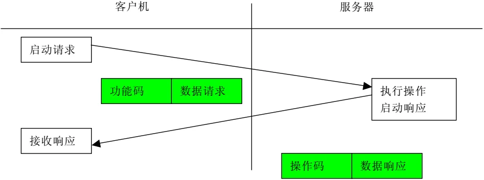
: The client that initiates MODBUS transaction processing creates a MODBUS application data unit. When a message is sent from the client to the server device, the function code indicates to the server which operation will be performed. The data field of the message sent from the client to the server device includes additional information, which the server uses to perform operations defined by the function code. If there are no errors related to requesting MODBUS functionality in a correctly received MODBUS ADU, then the response data field from the server to the client includes the request data.
The data field of the message sent from the client to the server device includes additional information, which the server uses to perform operations defined by the function code. If there are no errors related to requesting MODBUS functionality in a correctly received MODBUS ADU, then the response data field from the server to the client includes the request data.
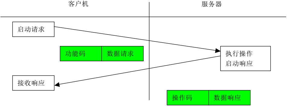
Normal transaction processing flow
If there is an error related to requesting MODBUS function, the domain includes an exception code, which the server application can use to determine the next operation to be executed. When the server responds to the client, it uses a function code field to indicate a normal (error free) response or the occurrence of some kind of error (known as an abnormal response). For a normal response, the server only responds to the original function code.
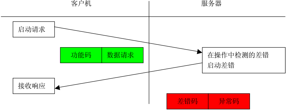
Abnormal transaction processing flow
2Operation design
Based on our understanding of the Modbus standard transaction process, we will design the specific operational procedures for the master and slave stations.
Main station operation process:
(1) Initialize the main station, station identifier, timer,
(2) Generate access command
Generate command ADU is implemented in two layers: network layer and link layer.
The network layer implements PDU that is independent of specific links (including function codes and data, where data refers to the transmitted data, not the values of variables, in fact, the quantity and address are also included). The corresponding file is mbpdu. c/. h, which implements data processing for Pud units, including commands and responses.
Implement ADU encapsulation at the link layer. The corresponding files are mbrtu. c/. h (along with mbtcp. c/. h and mbascii. c/. h), which encapsulate the ADU unit; As a slave, the response to write operations is also encapsulated here.
(3) Regularly send access commands, read commands must be polling, and write commands have higher priority. Pause the read command when there is a write command,
(4) Analyze the received data and perform the corresponding operation
Slave operation process:
(1) , Protocol stack initialization: Setting the slave station address, creating a data storage domain, access control
(2), receiving messages from the slave station and parsing
, manipulating the data after parsing the messages (reading and writing the values of the corresponding objects)
, generating responses
(3), generating response data and replying
3, command format
. Different function codes have different message formats, and we will briefly describe the information formats of the 8 function codes we will implement above.
(1) Function code 0x01: Read coil
In a remote device, use this function code to read 1 to 2000 consecutive states of the coil. The request PDU specifies the starting address, which is the designated first coil address and coil number. Address the coil from scratch. Therefore, addressing coils 1-16 are 0-15.
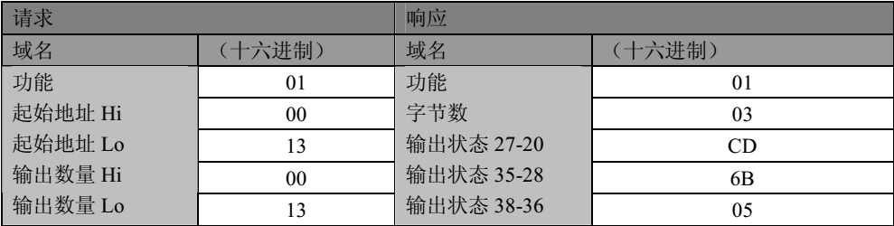
Divide the coils in the response message into one coil based on each bit in the data field. The indication status is 1=ON and 0=OFF. The LSB (least significant bit) of the first data byte includes the output addressed in the query. Repeat the process for other coils until the high-order end of this byte, and in the order from low to high in subsequent bytes. If the returned output quantity is not a multiple of eight, the remaining bits in the last data byte will be filled with zeros (up to the high-order end of the byte). The byte count field indicates the complete number of bytes in the data. The specific format example is as follows:
If the returned output quantity is not a multiple of eight, the remaining bits in the last data byte will be filled with zeros (up to the high-order end of the byte). The byte count field indicates the complete number of bytes in the data. The specific format examples are as follows:
(2) Function code 0x02: Read Discrete Input
In a remote device, use this function code to read continuous states from 1 to 2000 for discrete inputs. The request PDU specifies the starting address, which is the specified first input address and input number. Address inputs from scratch. Therefore, addressing inputs 1-16 are 0-15.
Divide the discrete input in the response message into one input based on each bit in the data field. The indication status is 1=ON and 0=OFF. The LSB (least significant bit) of the first data byte includes the input addressed in the query. The other inputs are repeated in sequence until the high-order end of this byte, and in the order from low to high in subsequent bytes. If the returned input quantity is not a multiple of eight, the remaining bits in the last data byte will be filled with zeros (up to the high-order end of the byte). The byte count field indicates the complete number of bytes in the data. The specific format example is as follows:
If the returned input quantity is not a multiple of eight, the remaining bits in the last data byte will be filled with zeros (up to the high-order end of the byte). The byte count field indicates the complete number of bytes in the data. The specific format examples are as follows:
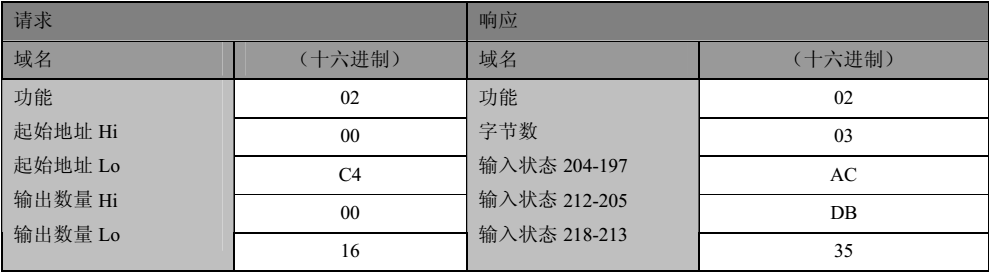
In fact, the data format of function codes 0x01 and 0x02 is exactly the same, and the operation method is also exactly the same. The only difference is the object of operation.
(3) Function code 0x03: Read and hold register
In a remote device, use this function code to read the contents of consecutive blocks of the hold register. The request PDU specifies the starting register address and the number of registers. Address registers from scratch. Therefore, addressing registers 1-16 are 0-15.
Divide the register data in the response message into two bytes per register, and directly adjust the binary content in each byte. For each register, the first byte contains high-order bits and the second byte contains low order bits. The specific format example is as follows:
For each register, the first byte contains high-order bits, and the second byte contains low order bits. The specific format examples are as follows:
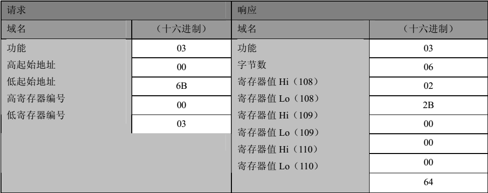
The length of the response information is related to the specific amount of data read.
(4) Function code 0x04: Read input register
In a remote device, use this function code to read consecutive input registers ranging from 1 to approximately 125. The request PDU specifies the starting address and number of registers. Address registers from scratch. Therefore, addressing input registers 1-16 is 0-15.
Divide the register data in the response message into two bytes for each register, and directly adjust the binary content in each byte.
For each register, the first byte contains high-order bits, and the second byte contains low order bits. The specific format examples are as follows:
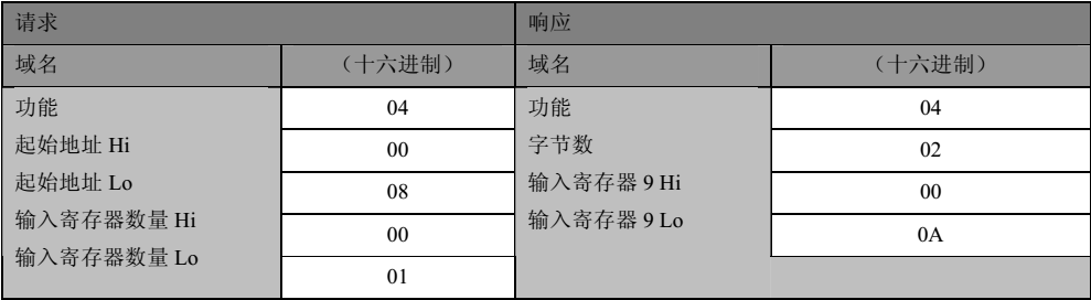
In fact, the data format of function codes 0x03 and 0x04 is exactly the same, and the operation method is also exactly the same. The only difference is the object of operation. The length of the response information is related to the specific amount of data read.
(5) Function code 0x05: Write a single coil
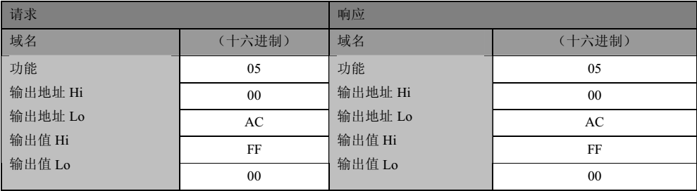
On a remote device, use this function code to write a single output as ON or OFF.
Request constants in the data field to indicate the ON/OFF status of the request. Hexadecimal value 0xFF00 requests output as ON. Hexadecimal value 0x0000 requests output as OFF. All other values are illegal and have no effect on the output.
The request PDU specifies the mandatory coil address. Address the coil from scratch. Therefore, addressing coil 1 is 0. The constant of the coil range indicates the requested ON/OFF state. Hexadecimal value 0XFF00 requests the coil to be ON. Hexadecimal value 0X0000 requests the coil to be OFF. All other values are illegal and have no effect on the coil.
Normal response is a response to a request, which is returned after writing the coil state. The specific format example is as follows:
(6) Function code 0x06: Write a single register
In a remote device, use this function code to write a single hold register.
The request PDU specifies the address written to the register. Address registers from scratch. Therefore, addressing register 1 is 0.
A normal response is a response to a request, which is returned after writing the register contents. The specific format example is as follows:
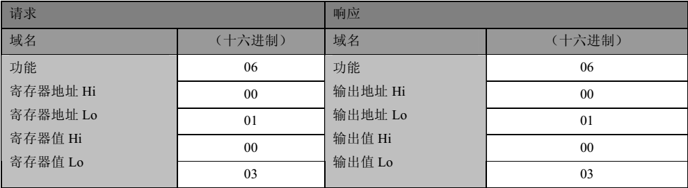
(7) Function code 0x0F: Write multiple coils
In a remote device, use this function code to force each coil in the coil sequence to be ON or OFF. The request PDU specifies the mandatory coil reference. Address the coil from scratch. Therefore, addressing coil 1 is 0.
The content of the requested data field indicates the requested ON/OFF status. The logical "1" in the domain bit position requests the corresponding output to be ON. The logical "0" in the domain bit position requests the corresponding output to be OFF.
Normal response returns function code, starting address, and forced coil quantity. The specific format example is as follows:
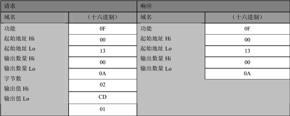
(8) Function code 0x10: Write multiple registers
In a remote device, use this function code to write consecutive register blocks (1 to about 120 registers).
specifies the value requested to be written in the request data field. Each register divides the data into two bytes.
Normal response returns the function code, starting address, and the number of registers written. The specific format example is as follows:
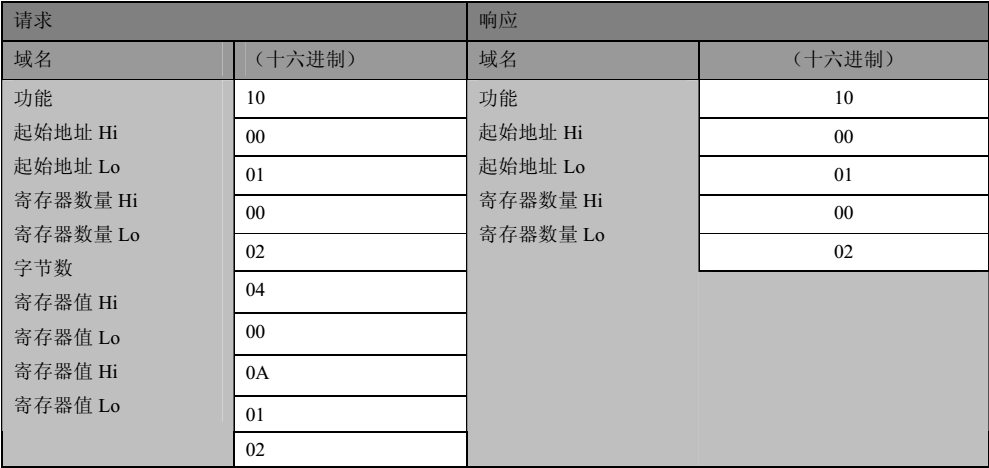
With a clear understanding of the above instructions, we can begin the development journey of the Modbus protocol. We have already explained the basic transactions of Modbus earlier, and based on this, we have designed the operation process of the master-slave station that we will implement. The generation of Modbus message frames is directly related to Modbus. Modbus message frames are also fundamental to implementing the Modbus communication protocol.
We have already explained the basic transactions of Modbus earlier, and based on this, we have designed the operation process of the master-slave station that we will implement. The generation of Modbus message frames is directly related to Modbus. Modbus message frames are also fundamental to implementing the Modbus communication protocol.
1, ModbusMessage Frame Analysis
The MODBUS protocol has some differences in message frames on different physical links, but when we analyze them, we will find that there are the following common parts in these different message frames, which are very important for us to achieve unified data operations. The specific description is as follows:
(1), Simple Protocol Data Unit
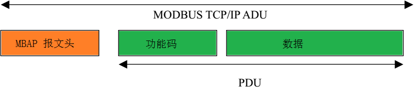
The MODBUS protocol defines a simple protocol data unit (PDU) that is independent of the underlying communication layer. The structure of a simple protocol data unit is as follows:

PDU is a part that is independent of the specific transmission network and contains function codes and data. For the MODBUS protocol on a specific bus or network, it only introduces some additional fields on the application data unit (ADU) based on the PDU. The development of the data unit part is the most basic part, mainly including two aspects of class capacity: firstly, generating the command part for the client (master) to access the server (slave); The second is to generate the server (slave) response to the client (master) reply section. For the Modbus protocol running on a serial link, the Application Data Unit (ADU) of
The development of the data unit is the most basic part, mainly involving two aspects of class content: firstly, generating commands for the client (master) to access the server (slave); The second is to generate the server (slave) response to the client (master) reply section.
(2andRTUis based on the PDU, with an address field added at the beginning and data checksum added at the end. The format is shown in the following figure:
For the Modbus protocol running on a serial link, its Application Data Unit (ADU) is based on the PDU, with an address field added at the beginning and data checksum added at the end. The format is shown in the following figure:
The address field is the address of the visited slave station, which is an 8-bit unsigned number with values from 0 to 255, but 0 and 255 have fixed meanings and cannot be used. The CRC check adopts the CRC16 check method. The application data unit (ADU) of
(3andTCPis a Modbus protocol that runs on an Ethernet link. Its application data unit (ADU) is formed by adding an MBAP header to the PDU, and the specific format is shown in the following figure:
The Modbus protocol running on an Ethernet link has an Application Data Unit (ADU) formed by adding an MBAP header to the PDU. The specific format is shown in the following figure:

For the MBAP header, it includes the following fields:
| Domain | Length | Description | Client | Server |
| Transaction Element Identifier | 2 bytes | MODBUS Request/Response Transaction Processing Identification Code | Client Startup | Server copies |
| Protocol Identifier | 2 bytes | 0=MODBUS Protocol | Client Startup | Server re copies |
| Length | 2 bytes | Number of bytes below | Client start (request) | Server start (response) |
| Unit identifier | 1 byte | Identification code of remote slave station connected on serial link or other bus | Client start | Server re copies |
From the table above, it can be seen that the message header is 7 bytes long:
Transaction identifier: Used for transaction pairing. In the response, the MODBUS server copies the transaction identifier of the request.
Protocol identifier: Used for multiplexing within the system. Identify MODBUS protocol through the value 0.
Length: The length field is the number of bytes in the next field, including the unit identifier and data field.
Unit identifier: This domain is used for routing within the system. Specially used for communication between MODBUS or MODBUS+serial link slave stations through a gateway between Ethernet TCP-IP network and MODBUS serial link. Simply put, it refers to the address field in the serial link. The MODBUS client sets this field in the request, and the server must return this field with the same value in the response.
2Specific Composition Analysis of Data Frame
From the above analysis of the message formats of simple protocol basic data elements, RTU application data units, and TCP application data units, we found that the basic data unit part is consistent. Therefore, we can consider layering and encapsulating the protocol operation part:
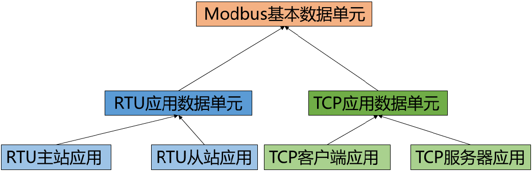
Initially, we implemented the Modbus basic data unit, which is a data common part that is independent of specific applications and only needs to be encapsulated once. For the development of this part, we only need to follow the Modbus standard protocol. This time, we plan to implement 8 functions:
| Function code | Name | Implementation | 55] 0x01 |
| 0x01 | Read Coil | Yes | Read Read Read Read Write State |
| 0x02 | Read Discrete Input | Yes | Read Read Read Read State |
| 0x03 | Read Hold Register | Yes | Read Read Read Read Read Write Register |
| 0x04 | Read Input Register | Yes | Read Read Read Read Read Register |
| 0x05 | Write a single coil | Yes | Write a single read-write state quantity |
| 0x06 | Write a single register | Yes | Write a single read-write register quantity |
| 0x0F | Write multiple coils | Yes | Write multiple read-write state quantities |
| 0x10 | Write multiple registers | is | Write multiple read-write register quantities |
These 8 are also the most important functions defined by the Modbus protocol, and now the message for these function codes The format description is as follows:
(1Reading coil0x01
Reading coil is a type of switch that can be written, because Modbus protocol originated from PLC applications, and coil is the name for the DO output of PLC, generally suitable for the master station to issue operation commands to the slave station. The data format for reading this state variable with read-write function is as follows:
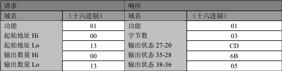
The command format issued is: domain name+function code+starting address+quantity.
(2Read Discrete Input0x02
Read Status Input is to read a read-only switch signal, corresponding to the digital input in the PLC. The format for reading the input of this read-only switch is as follows:
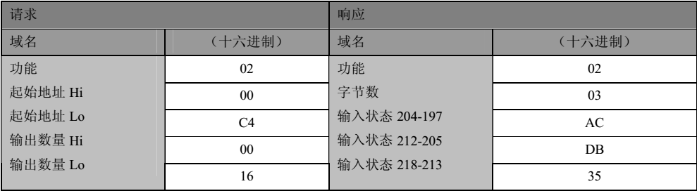
The command format issued is: domain name+function code+starting address+quantity.
(3Read and hold register0x03
A hold register refers to 16 bit data that can be read and written. It can be used to represent various data through a single or multiple hold registers, such as 8-bit integers, 16 as integers, 32-bit integers, 64 bit integers, and single/double precision floating-point numbers. The message format for reading and holding registers is as follows:
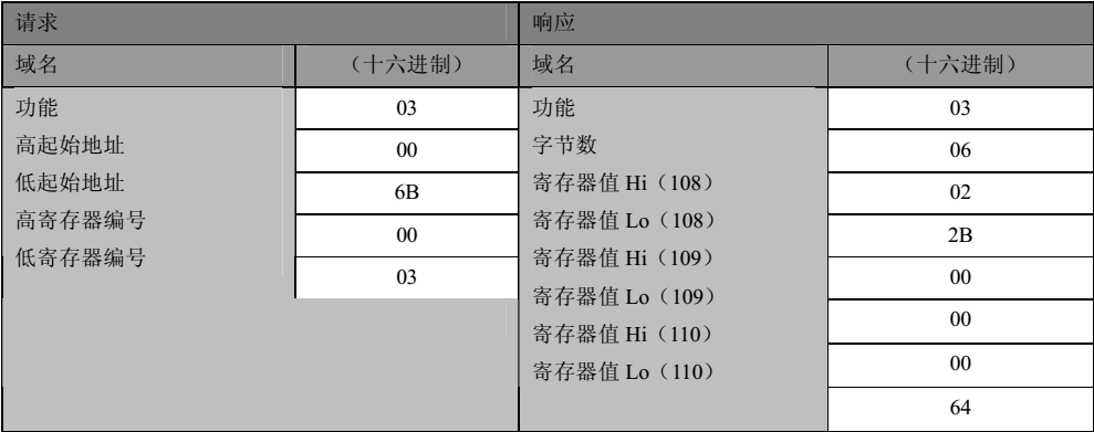
The command format issued is: domain name+function code+starting address+quantity.
(4Read Input Register0x04
The input register is a read-only form of 16 bit data. Single or multiple input registers can represent 8-bit integers, 16 as integers, 32-bit integers, 64 bit integers, and single or double precision floating-point numbers. The message format for reading the input register is as follows:
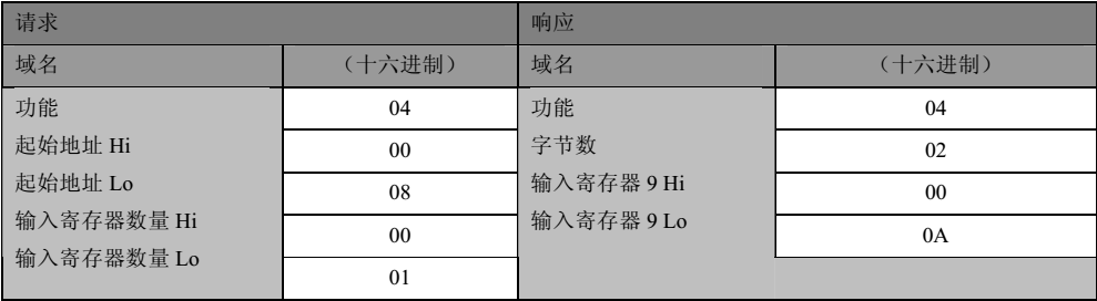
The command format issued is: domain name+function code+starting address+quantity.
(5Writing a single coil0x05
Writing a single coil quantity is to operate on a single readable and writable switch quantity, but it is not directly writing "0" or "1", but sending 0xFF00 when "1" needs to be written; When it is necessary to write "0", the specific message format for sending 0x0000 is as follows:
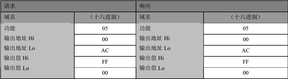
The command format it issues is: domain name+function code+output address+output value. The specific content of the command is different from the read operation, but the format is completely the same. In programming, actual read and write can be encapsulated together.
(6) Write a single register0x06
Writing a single register is to operate on a single hold register, and the data format remains the same. In practical applications, it is only applicable to operations on 16 bit integer data, and not for floating-point numbers, etc.
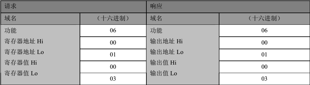
The command format it issues is: domain name+function code+output address+output value. The specific content of the command is different from the read operation, but the format is completely the same. In programming, actual read and write can be encapsulated together.
(7) Write multiple coils0x0F
The operation object for writing multiple coils is exactly the same as writing a single coil, except for the quantity and operation value, especially the value. Writing "1" means "1", and writing "0" means "0", which is the difference from writing a single coil.
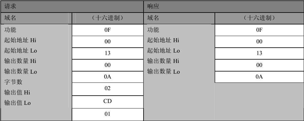
The command format it issues is: domain name+function code+starting address+output quantity+byte count+output value. The command message has significant differences from the previous read and write operations and must be processed separately.
(8) Write multiple registers0x10
Writing multiple registers means performing operations on multiple readable and writable registers simultaneously, and the format of data messages is consistent with writing to multiple coils.
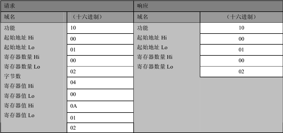
The command format it issues is: domain name+function code+starting address+output quantity+byte count+output value.
3Programming of Basic Data Units
After the above analysis, we found that regardless of the physical link on which the application data is implemented, the basic data segments of the device are the same. In fact, the format of adding domain segments is also the same, so we will
The domain name and PDU are implemented together as the most basic data unit.
The implementation of basic data units can be divided into two situations: first, when acting as the master station (client), issuing commands to the slave station (server); The second is the response to commands from the master station (client) when acting as a slave station (server). So we encapsulate these two situations into two basic functions:
(1) When acting as an RTU master (TCP client), generate commands to read and write RTU slave (TCP server) objects:
uint16_t GenerateReadWriteCommand(ObjAccessInfo objInfo,bool *statusList,uint16_t *registerList,uint8_t *commandBytes)
The parameters are the basic information of the PDU unit, the corresponding data of the write object, and the generated command bytes. The return value is the length of the generated command.
(2) When acting as a slave (server), generate a response for the master read access. For the response, since the write operation response is actually a part of the command copied from the master station (client), the actual response we need to generate includes the 0x01, 0x02, 0x03, and 0x04 function codes.
uint16_t GenerateMasterAccessRespond(uint8_t *receivedMessage,bool *statusList,uint16_t *registerList,uint8_t *respondBytes)
The parameters are the received information, the data of the read object, and the response message returned. The return value is the length of the response message returned.
4, RTUProgramming of application data units
For RTU application data units, the message format is "domain name+PDU+CRC", and we have already implemented domain name+PDU in the previous section. Therefore, to implement the RTU data unit, we only need to add CRC check to complete it.
The implementation of RTU data units can be divided into two situations: first, when acting as the master station, issuing commands to the slave stations; The second is to respond to commands from the master station as a slave station. So we encapsulate these two situations into two basic functions:
(1) When acting as an RTU master, generate commands to read and write RTU slave objects:
/*Generate commands for reading and writing slave data objects, with a command length including 2 checksum bytes*/
uint16_t SyntheticReadWriteSlaveCommand(ObjAccessInfo slaveInfo,bool *statusList,uint16_t *registerList,uint8_t *commandBytes)
The parameters are the basic information of the slave station, the data list issued, and the final command array generated. The return value is the length of the command.
(2) As a slave station, generate a response for the master station's read access:
/*Generate a response from the slave station to the master station*/
uint16_t SyntheticSlaveAccessRespond(uint8_t *receivedMessage,bool *statusList,uint16_t *registerList,uint8_t *respondBytes)
The parameters are the received information, the returned data list, and the generated response information list. The return value is the length of the response information list.
5, TCPProgramming of application data units
For TCP application data units, unlike RTU type, the starting message format is "MBAP header+PDU", and PDU units are defined earlier, so only the MBAP header needs to be added. In fact, the implementation format of the MBAP header is fixed.
The implementation of TCP application data units can also be divided into two situations: first, when acting as a client, issuing commands to the server; The second is the response to client commands when acting as a server. So we encapsulate these two situations into two basic functions:
(1) When acting as a TCP client, generate commands for reading and writing TCP server objects:
/*Generate commands for reading and writing server objects*/
uint16_t SyntheticReadWriteTCPServerCommand(ObjAccessInfo objInfo,bool *statusList,uint16_t *registerList,uint8_t *commandBytes)
(2) As a server, generate responses for client read and write access:
/*Synthesize the response to server access, with the return value being the command length*/
uint16_t SyntheticServerAccessRespond(uint8_t *receivedMessage,bool *statusList,uint16_t *registerList,uint8_t *respondBytes)
6Conclusion
In fact, by this point we have basically implemented the Modbus basic protocol, and even using these basic operations can achieve Modbus communication. In fact, many people write Modbus communication protocols that are even simpler than this and can also achieve some Modbus communication functions. Of course, this is not our goal, otherwise we wouldn't need to develop a dedicated library. What we need is to further encapsulate it to make it more universal and user-friendly.
After completing the previous work, we can implement targeted applications. First, let's implement the server-side application of Modbus TCP. Of course, we are not making specific applications, but rather encapsulating the server-side applications of Modbus TCP for calling when needed.
We do not involve the TCP protocol here, and this part is not necessarily related to Modbus. We are only running the Modbus protocol at its application layer.
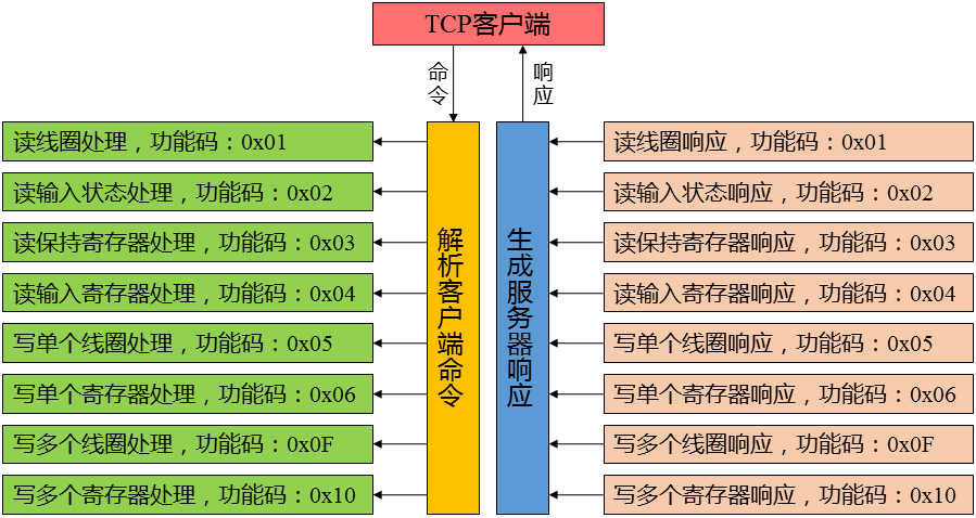
For Modbus TCP servers, we need to implement several functions: firstly, parsing the received client commands. We only support the commonly used functions mentioned in the previous 8. Secondly, after the parsing is completed, we need to implement operations corresponding to various functional codes. The specific architecture is as follows:
1Command parsing
After receiving the client's request as a passive end, the server processes the installation request. So after receiving the information, the server first parses it. Here, we only need a parsing function to complete it. In specific applications, we only need to call this function to parse the received information.
/*Analyze the received information and return the length of the response command*/
uint16_t ParsingClientAccessCommand(uint8_t *receivedMessage,uint8_t *respondBytes)
Actually, externally speaking, it is only visible when there is one function. When we are developing a TCP Server application, we call this function.
2Command processing
After the command is parsed, different processing is performed according to different function codes. We support 8 types of function codes, and each function corresponds to a processing part. Many times, people will process based on the parsing result during parsing, which inevitably requires a large number of parsing functions. To simplify the operation, we encapsulate the processing part corresponding to each function code as a function. Then use a function pointer array to dynamically call these functions, simplifying them.
Firstly, we need 8 functions to handle the corresponding function code operations:
/*Process the command to read the coil status*/
static uint16_t HandleReadCoilStatusCommand(uint16_t startAddress,uint16_t quantity,uint8_t *receivedMessage,uint8_t *respondBytes)
/*Processing read input status commands*/
static uint16_t HandleReadInputStatusCommand(uint16_t startAddress,uint16_t quantity,uint8_t *receivedMessage,uint8_t *respondBytes)
/*Processing read hold register commands*/
static uint16_t HandleReadHoldingRegisterCommand(uint16_t startAddress,uint16_t quantity,uint8_t *receivedMessage,uint8_t *respondBytes)
/*Processing read input register commands*/
static uint16_t HandleReadInputRegisterCommand(uint16_t startAddress,uint16_t quantity,uint8_t *receivedMessage,uint8_t *respondBytes)
/*Process the command to write a single coil*/
static uint16_t HandleWriteSingleCoilCommand(uint16_t coilAddress,uint16_t coilValue,uint8_t *receivedMessage,uint8_t *respondBytes)
/*Process the command to write a single register*/
static uint16_t HandleWriteSingleRegisterCommand(uint16_t registerAddress,uint16_t registerValue,uint8_t *receivedMessage,uint8_t *respondBytes)
/*Process writing multiple coil states*/
static uint16_t HandleWriteMultipleCoilCommand(uint16_t startAddress,uint16_t quantity,uint8_t *receivedMessage,uint8_t *respondBytes)
/*Process writing multiple register states*/
static uint16_t HandleWriteMultipleRegisterCommand(uint16_t startAddress,uint16_t quantity,uint8_t *receivedMessage,uint8_t *respondBytes)
Then we define a function pointer array to call the following function:
uint16_t (*HandleClientCommand[])(uint16_t,uint16_t,uint8_t *,uint8_t *)={HandleReadCoilStatusCommand,
HandleReadInputStatusCommand,
HandleReadHoldingRegisterCommand,
HandleReadInputRegisterCommand,
HandleWriteSingleCoilCommand,
HandleWriteSingleRegisterCommand,
HandleWriteMultipleCoilCommand,
HandleWriteMultipleRegisterCommand};
3Generation of Response
The generation of response commands has already been discussed in the second article. It should be noted that the specific values for writing data and obtaining read data will be implemented in separate files, as TCP and RTU are the same. We will explain this in subsequent chapters.
This time we package the Modbus TCP Client application. Similarly, we are not making specific applications, but rather implementing the basic functions of TCP clients. We encapsulate the functionality of the TCP client as a function to be called during the development of specific applications.
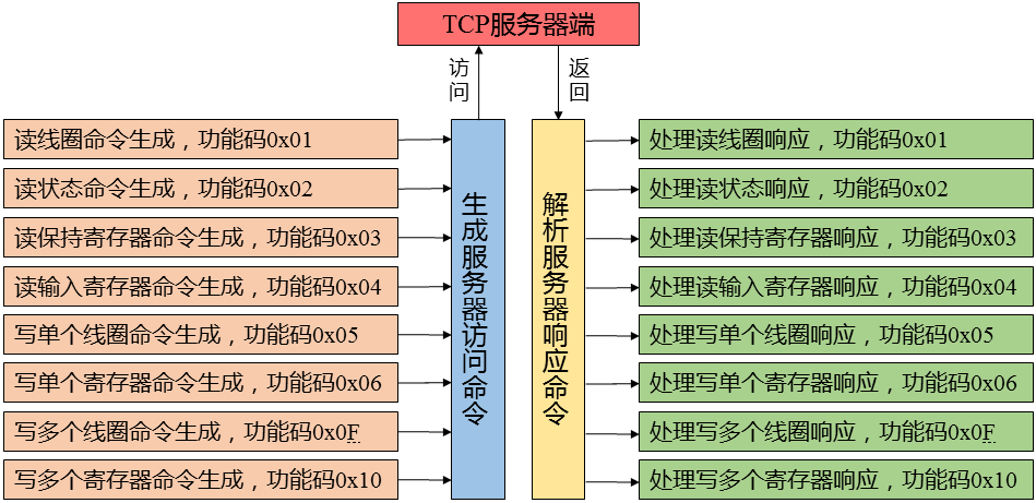
For TCP clients, we mainly implement two functions: one is to generate commands to access TCP servers, supporting a total of 8 function codes. The second is to parse the information returned by the TCP server and perform various operations based on the results, which also supports the operation of the 8 functions. The specific software access structure is as follows:
1Generation of access commands
As an active interactive end, the client needs to send various operation request commands to the server. So for TCP clients, the first step is to generate commands to access the server. To generate commands, simply follow the standard protocol format, and currently we only support the 8 function codes mentioned earlier.
/*Generate commands to access the server*/
uint16_t CreateAccessServerCommand(ObjAccessInfo objInfo,void *dataList,uint8_t *commandBytes)
In this way, when developing specific client applications, only this function needs to be called to generate commands to access the server.
2Analysis of response information
As mentioned in the previous section, after receiving the command, the server processes it and generates response information to return to the client. After receiving the command, the client first needs to parse the response information, and the parsing process is actually the same as that of the server. The difference is that there is no need to generate response information based on the parsing results anymore.
/*Analyze the corresponding information received from the server*/
void ParsingServerRespondMessage(uint8_t *recievedMessage)
In this way, when developing client applications, we can call this function to parse the response information.
3Response processing
For the parsed information, we need to implement operations according to the situation, such as modifying variable values. The main supported opcodes are 8, and theoretically each corresponding function code will have different operations. However, in fact, since the write operation command no longer requires any operations, the corresponding operations are actually only the 4 function codes of the read operation.
/*Process the return information of the slave station status quantity and read the coil status bit 0x01 function code*/
static void HandleReadCoilStatusRespond(uint8_t *receivedMessage,uint16_t startAddress,uint16_t quantity)
/*Process the return information of the slave station status quantity and read the function code 0x02 of the input status bit*/
static void HandleReadInputStatusRespond(uint8_t *receivedMessage,uint16_t startAddress,uint16_t quantity)
/* Process the return message of reading the slave register value, read and hold register 0x03 function code) */
Static void HandleReadHolding Register Response (uint8_t * received Message, uint16ut startAddress, uint16ut quantity)
/* Process the return message of reading the slave register value, read input register 0x04 function code */
Static void HandleReadInputRegister Response (uint8_t * received Message, uint16ut startAddress, uint16ut quantity)
Similarly, we also define a A function pointer array is used to implement the calling of these functions:
void (*HandleServerRespond[])(uint8_t *,uint16_t,uint16_t)={HandleReadCoilStatusRespond, HandleReadInputStatusRespond, HandleReadHoldingRegisterRespond, HandleReadInputRegisterRespond};
In this way, the encapsulation of the TCP client is completed, but the specific data processing part needs to be determined in the development of specific applications.
Modbus is divided into Slave and Master on the serial link. In this section, we will develop Slave. For Modbus RTU slave stations, the functions that need to be implemented are actually the same as the server-side of Modbus TCP. The operation process is also the same. Firstly, we receive the access command from the main station and parse the command message. Here, we only implement the 8 function codes mentioned earlier. Next, we will perform corresponding operations based on the parsing results. The specific software access structure is as follows:
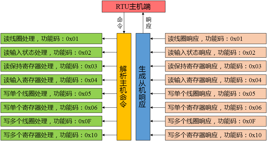
It is not difficult to see from the above figure that there are actually three steps:
Step 1: parsing after receiving the command. The parsing method is the same as the class formula in the previous sections. Step 2: Operate based on the parsing results. Including more commands to modify or retrieve the value of variables. Step 3: Generate a response and return it to the host.
Step 2: Operate based on the parsing results. Including more commands to modify or retrieve the value of variables.
Step 3: Generate a response and return it to the host.
1, After receiving the command message from the host, the slave machine parses it. We currently support the 8 function codes shown in the above figure.
After receiving the command message from the host, the slave machine parses it and currently supports the 8 function codes shown in the above figure.
/* Parses the received message and returns the synthesized reply message and the byte length of the message, using the callback function */
uint16ut ParsingMasterAccessCommand (uint8_t * receptidMessage, uint8_t * responsiveBytes, uint16ut rxLength)
. This function receives the received message and generates a response message, with the return value being the length of the response message. In developing an application, simply send the received message to this function and return the generated response information to the client. After parsing, whether it is a read command or a write command, corresponding operations need to be performed. We encapsulate different operations based on different function codes:
2Result operation
After parsing, both read and write commands require corresponding operations. We encapsulate different operations based on different function codes:
/* Processing Read Coil Status Command */
static uint16_t HandleReadCoilStatusCommand(uint16_t startAddress,uint16_t quantity,uint8_t *receivedMessage,uint8_t *respondBytes)
/*Processing read input status commands*/
Static uint16ut HandleReadInputStatus Command (uint16ut startAddress, uint16ut quantity, uint8_t * received Message, uint8_t * responded bytes)
/*Processing read hold register commands*/
static uint16_t HandleReadHoldingRegisterCommand(uint16_t startAddress,uint16_t quantity,uint8_t *receivedMessage,uint8_t *respondBytes)
/* Process Read Input Register Command */
static uint16ut HandleReadInputLoadCommand (uint16ut startAddress, uint16ut quantity, uint8_t * received Message, uint8_t * responded bytes)
/* Process Write Single Coil Command */
static uint16ut HandleWriteSingleCoil Command (uint16ut coinAddress, uint16ut coinValue, uint8_t * received Message, uint8_t * responded bytes)
/* Process Write Single Coil Command */
static uint16ut HandleWriteSingleLoadCommand (uint16ut registrant Address, uint16ut registrant Value, uint8_t * received Message, uint8_t * responded bytes)
/* Process writing multiple coil states */
static uint16ut HandleWriteMultipleCoCommand (uint16ut startAddress, uint16ut quantity, uint8_t * received Message, uint8_t * responded bytes)
/* process writing multiple register states */
static uint16ut HandleWriteMultipleReadCommand (uint16ut startAddress, uint16ut quantity, uint8_t * received Message, uint8_t * responded bytes)
Similarly, we also define a function pointer array to implement these 8 functions. Function call:
uint16_t (*HandleMasterCommand[])(uint16_t,uint16_t,uint8_t *,uint8_t *)={HandleReadCoilStatusCommand,
HandleReadInputStatusCommand,
HandleReadHoldingRegisterCommand,
HandleReadInputRegisterCommand,
HandleWriteSingleCoilCommand,
HandleWriteSingleRegisterCommand,
HandleWriteMultipleCoilCommand,
HandleWriteMultipleRegisterCommand};
3, Generate Slave Response
After processing, corresponding information of the slave needs to be generated. Whether it is a read or write operation command, we generate a response message when processing the corresponding function code. In this way, when developing applications, all the functions can be achieved by calling the parsing function data. In this section, we will encapsulate the last application (Modbus RTU Master application), and the development of RTU Master is consistent with the development of TCP client. Similarly, we are not doing specific applications, but rather implementing the basic functions of the RTU master station. We encapsulate the functions of the RTU master station into functions for calling during the development of specific applications. For the RTU master station, we mainly implement two functions: one is to generate commands to access the RTU slave station, which supports a total of 8 function codes. The second is to parse the information returned by the RTU from the station end and perform various operations based on the results, which also supports the operation of the 8 functions. The specific software access structure is as follows:
In this section, we will encapsulate the last application (Modbus RTU Master application), and the development of RTU Master is consistent with the development of TCP client. Similarly, we are not doing specific applications, but rather implementing the basic functions of the RTU master station. We encapsulate the functions of the RTU master station into functions for calling during the development of specific applications.
For the RTU master station, we mainly implement two functions: one is to generate commands to access the RTU slave station, supporting a total of 8 functional codes. The second is to parse the information returned by the RTU from the station end and perform various operations based on the results, which also supports the operation of the 8 functions. The specific software access structure is as follows:
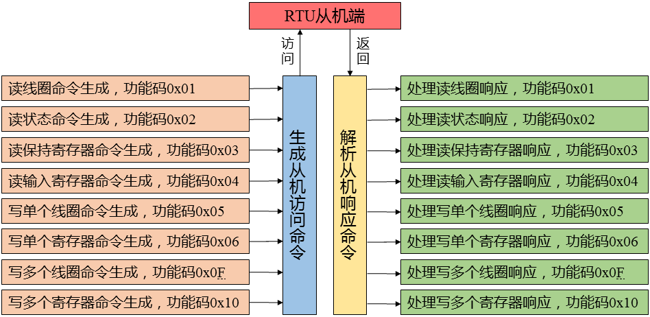
1, The generation of access commands
As the active interactive end, the client needs to send various operation request commands to the server. So for the RTU master station, the first step is to generate commands to access the server. To generate commands, simply follow the standard protocol format, and currently we only support the 8 function codes mentioned earlier.
/* Generate commands to access the slave station */
uint16ut CreateAccessSlaveCommand (ObjAccessInfo objInfo, void * dataList, uint8_t * commandbytes)
This way, when developing specific client applications, only this function needs to be called to generate commands to access the server. As described in the previous section, after receiving the command, the server processes it and generates response information to return to the client. After receiving the command, the client first needs to parse the response information, and the parsing process is actually the same as that of the server. The difference is that there is no need to generate response information based on the parsing results anymore.
2Analysis of response information
As mentioned in the previous section, after receiving the command, the server processes it and generates response information to return to the client. After receiving the command, the client first needs to parse the response information, and the parsing process is actually the same as that of the server. The difference is that there is no need to generate response information based on the parsing results anymore.
/* Parse the corresponding information received from the slave station */
void ParsingSlaveRespondMessage (uint8_t * recevedMessage)
In this way, when developing client applications, we can call this function to parse the response information.
3, Response Processing
For the parsed information, we need to implement operations according to the situation, such as modifying variable values. The main supported opcodes should be 8, and theoretically each corresponding function code will have different operations. However, in fact, since the write operation command no longer requires any operations, the corresponding operations are actually only the 4 function codes of the read operation.
/*Process the return information of the slave station status quantity and read the coil status bit 0x01 function code*/
static void HandleReadCoilStatusRespond(uint8_t *receivedMessage,uint16_t startAddress,uint16_t quantity)
/*Process the return information of the slave station status quantity and read the function code 0x02 of the input status bit*/
static void HandleReadInputStatusRespond(uint8_t *receivedMessage,uint16_t startAddress,uint16_t quantity)
/*Process the return information of reading the slave station register value, and read the function code 0x03 of the hold register*/
static void HandleReadHoldingRegisterRespond(uint8_t *receivedMessage,uint16_t startAddress,uint16_t quantity)
/*Process the return information of the slave station register value and read the function code 0x04 of the input register*/
static void HandleReadInputLoadResponse (uint8_t * received Message, uint16ut startAddress, uint16ut quantity)
Similarly, we also define a function pointer array to implement the calling of these functions:
void (*HandleServerRespond[])(uint8_t *,uint16_t,uint16_t)={HandleReadCoilStatusRespond, HandleReadInputStatusRespond, HandleReadHoldingRegisterRespond, HandleReadInputRegisterRespond};
At this point, the encapsulation of the RTU master station is completed, but the specific data processing part needs to be determined in the development of specific applications.
Various applications have been developed earlier, but there has been no mention of a problem where you are performing read and write operations on specific data. For Modbus, there are four standard types of data: coil data (address: 0000x), input state data (address: 1000x), hold register data (address: 4000x), and input register data (address: 3000x). Our purpose of communication is to manipulate this data, but our previous packaging did not mention data processing. In fact, it is impossible to consider this point because the specific application data varies greatly and cannot be encapsulated. How can we solve this problem? Next, we will address this type of issue.
1, The encapsulation of data processing functions
We consider that the processing of data is essentially the same whether it is in the RTU master station, RTU slave station, TCP client, or TCP server. As long as the specific data structure of the application is determined, the processing method will also be determined. In view of this, the method we adopt is to define a function of weakening type. As follows:
/*Get the value of the desired amount of Coil to be read*/
__weak void GetCoilStatus(uint16_t startAddress,uint16_t quantity,bool *statusList)
{
//If specific content needs to be implemented in Modbus TCP Server/RTU Slave applications
}
/*Get the value of the InputStatus quantity you want to read*/
__weak void GetInputStatus(uint16_t startAddress,uint16_t quantity,bool *statusValue)
{
//If specific content needs to be implemented in Modbus TCP Server/RTU Slave applications
}
/* Get the value of the hold register you want to read */
__weak void GetHolding Register (uint16ut startAddress, uint16ut quantity, uint16ut * register Value)
{
//If you need to implement it in Modbus TCP Server/RTU Slave applications
}
/* Get the value of the input register you want to read*/
__weak void GetInputRegister(uint16_t startAddress,uint16_t quantity,uint16_t *registerValue)
{
//If specific content needs to be implemented in Modbus TCP Server/RTU Slave applications
}
/*Set the value of a single coil*/
__weak void SetSingleCoil(uint16_t coilAddress,bool coilValue)
{
//If specific content needs to be implemented in Modbus TCP Server/RTU Slave applications
}
/*Set the value of a single register*/
__weak void SetSingleRegister(uint16_t registerAddress,uint16_t registerValue)
{
//If specific content needs to be implemented in Modbus TCP Server/RTU Slave applications
}
/*Set values for multiple coils*/
__weak void SetMultipleCoil(uint16_t startAddress,uint16_t quantity,bool *statusValue)
{
//If specific content needs to be implemented in Modbus TCP Server/RTU Slave applications
}
/*Set the values of multiple registers*/
__weak void SetMultipleRegister(uint16_t startAddress,uint16_t quantity,uint16_t *registerValue)
{
//If specific content needs to be implemented in Modbus TCP Server/RTU Slave applications
}
/*Update the coil status read back*/
__weak void UpdateCoilStatus(uint16_t startAddress,uint16_t quantity,bool *stateValue)
{
//Implement
}
/* update the read back input status value */
__weak void Updating Input Status (uint16ut startAddress, uint16ut quantity, boolean * stateValue)
{
//Implement
}
//* in the client (master) application. Update the coil status read back */
__weak void Updating Holding Register (uint16ut startAddress, uint16ut quantity, uint16ut * register Value)
{
//Implement
}
/* Update the coil status read back in the client (master) application*/
__weak void UpdateInputResgister(uint16_t startAddress,uint16_t quantity,uint16_t *registerValue)
{
//When developing specific applications, we only need to implement the corresponding functions in the application to make the functionality complete. As for how to handle specific data, it depends on the data format in the specific application. Of course, not all of these functions need to be implemented, just implement them according to your own needs.
}
When developing specific applications, we only need to implement corresponding functions in the application to make the functionality complete. As for how to handle specific data, it depends on the data format in the specific application. Of course, not all of these functions need to be implemented, just implement them according to your own needs.
2Regarding the issue of big and small ends
When it comes to data communication, there is an unavoidable problem, which is the issue of big and small ends. For the Modbus protocol, the big end mode is used, which means that the low bit address stores the high bit byte data, and the high bit address stores the low bit byte data. When conducting multi byte data communication, the issue of size difference becomes apparent. For example, the order in which a floating-point number is stored in different systems can result in incorrect parsing of the data you read or write. So we must consider this when processing data packets. When it comes to Modbus communication, cyclic redundancy check (CRC) is inevitable, especially on standard serial RTU links where it is essential. Not only that, but in other developments, the CRC
When conducting multi byte data communication, the issue of size difference becomes apparent. For example, the order in which a floating-point number is stored in different systems may differ, resulting in incorrect parsing of the data you read or write. So we must consider this when processing data packets.
When it comes to Modbus communication, cyclic redundancy check (CRC) is inevitable, especially on standard serial RTU links where it is essential. Not only that, but CRC is also frequently used in other developmentsalgorithmis often used to verify various data. In this way, we need to study the cyclic redundancy check (CRC) algorithm.
1, CRCBrief Description
Cyclic Redundancy Check (CRC) is a data transmission error detection function that performs polynomial calculations on data and attaches the results to the end of the frame. The receiving device also executes similar algorithms to ensure the correctness and integrity of data transmission. The basic idea of CRC check is to use linear coding theory to generate a supervision code (i.e. CRC code) of r bits at the sending end according to a certain rule based on the k-bit binary code sequence to be transmitted, and attach it to the information to form a new binary code sequence with a total of (k+r) bits, which is finally sent out. At the receiving end, a check is performed based on the rules followed between the information code and CRC code to determine if there are any errors during transmission.
The basic idea of CRC check is to use linear coding theory to generate a supervision code (i.e. CRC code) r bits for check at the sending end according to a certain rule based on the k-bit binary code sequence to be transmitted, and attach them to the information to form a new binary code sequence with a total of (k+r) bits, and finally send it out. At the receiving end, a check is performed based on the rules followed between the information code and CRC code to determine if there are any errors during transmission.
The essence of CRC is the remainder of modulo 2 division, and the type of CRC varies depending on the divisor used. Usually, the divisor of CRC is represented by a generating polynomial. The most commonly used polynomial generators for CRC codes are as follows:
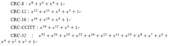
Different generating polynomials naturally result in different results. In fact, CRC-16 is used in Modbus communication.
2Algorithm Analysis
The encoding method of CRC check code is to divide the binary data t (x) to be sent by the generating polynomial g (x), and use the remainder as the CRC check code. The implementation steps are as follows:
Let the data block to be sent be an m-bit binary polynomial t (x), generating a polynomial of order r g (x). Add r zeros at the end of the data block, and the length of the data block increases to m+r bits, corresponding to a binary polynomial of. Using the generating polynomial g (x) to remove, obtain a binary polynomial y (x) with a remainder of order r-1. This binary polynomial y (x) is the CRC checksum encoded by the generator polynomial g (x) for t (x). Subtract y (x) in modulus 2 to obtain a binary polynomial. It is the string to be sent that contains the CRC checksum.
From the encoding rules of CRC, it can be seen that CRC encoding actually converts the m-bit binary polynomial t (x) sent by proxy into an m+r-bit binary polynomial that can be divided by g (x). Therefore, during decoding, g (x) can be removed from the received data. If the remainder bit is zero, it indicates that there are no errors in the transmission process; If the remainder is not zero, there must be an error during transmission. Many CRC hardware decoding circuits perform error detection in this way. At the same time, it can be regarded as a combination of t (x) and CRC check code, so when decoding, the received binary data is removed from the tail r-bit data, and the original data is obtained.
In fact, the actual CRC calculation is usually somewhat different from the one described above. This is because the most basic CRC division has a clear flaw, which is that adding some zeros at the beginning of the data stream does not affect the final checksum result. To compensate for this deficiency, two concepts were introduced: one is the "remainder initial value" and the other is the "result XOR value". The so-called 'remainder initial value' refers to the initial value assigned to the storage variable before calculating the CRC value. The corresponding 'result XOR value' is the final XOR operation performed on the variable value after the calculation is completed to obtain the verification result.
| Name | Checksum bit width | Generate polynomial | Divisor (polynomial) | Remainder initial value | XOR value of the result |
| CRC-4 | 4 | x4+x+1 | 3 | ||
| CRC-8 | 8 | x8+x5+x4+1 | 0x31 | ||
| CRC-8 | 8 | x8+x2+x1+1 | 0x07 | ||
| CRC-8 | 8 | x8+x6+x4+x3+x2+x1 | 0x5E | ||
| CRC-12 | 12 | x12+x11+x3+x+1 | 80F | ||
| CRC-16 | 16 | x16+x15+x2+1 | 0x8005 | 0x0000 | 0x0000 |
| CRC-CCITT | 16 | x16+x12+x5+1 | 0x1021 | 0xFFFF | 0x0000 |
| CRC-32 | 32 | x32+x26+x23+x22+x16+x12+x11+x10+x8+x7+x5+x4+x2+x1+1 | 0x04C11DB7 | 0xFFFFFFFF | 0xFFFFFFFF |
| CRC-32c | 32 | x32+x28+x27+...+x8+x6+1 | 1EDC6F41 |
At this point, we can describe the implementation process of this algorithm:
Step 1: Define the CRC storage variable and assign it the "remainder initial value". Step 2: XOR the first 8-bit character of the data with the CRC storage variable and store the result in the CRC storage variable.
Step 2: XOR the first 8-bit character of the data with the CRC storage variable and store the result in the CRC storage variable.
Step 3: Move the CRC storage variable one bit to the right, zero the MSB, remove and check the LSB.
Step 4: If LSB is 0, repeat step 3; If LSB is 1, the CRC register is different from 0x31.
Step 5: Repeat steps 3 and 4 until all 8 shifts are completed. At this point, an 8-bit data processing is completed.
Step 6: Repeat steps 2 to 5 until all data is processed.
Step 7: The final CRC storage variable is the CRC value after performing a NOR operation on the content of the variable and the XOR value of the result.
3Code implementation
With the preparations made earlier, the code for implementing CRC check is actually quite simple. There are various methods to implement this process, including two commonly used ones: one is the direct calculation method, which calculates according to the previous steps; The second is the driver table method, which stores some data and directly obtains calculations. Because CRC-16 is used in Modbus, we will use it as an example to implement it.
(1) Direct calculation method
The direct calculation method is simple and straightforward, and it is also relatively easy to write programs. Taking CRC-16 as an example, its polynomial is denoted as 0x8005, and because its XOR value is 0x0000, it can be omitted. The specific code is as follows:
#define Initial_Value 0x0000
#define EOR 0x0000
#define POLY16 0x8005
uint16_t CRC16(uint8_t *buf,uint16_t length)
{
uint16_t crc16,data,val;
crc16 = Initial_Value;
for(int i=0;i<length;i++)
{
if((i % 8) == 0)
{
data = (*buf++)<<8;
}
val = crc16 ^ data;
crc16 = crc16<<1;
data = data <<1;
if(val&0x8000)
{
crc16 = crc16 ^ POLY16;
}
}
return crc16;
}
(2) Drive table method
For the direct calculation method, although it is simple and straightforward, efficiency can sometimes be a problem. Therefore, in Modbus communication, we usually use the driver table method to achieve:
//CRC-16 high 8-bit data area
const uint8_t auchCRCHi[] = {
0x00, 0xC1, 0x81, 0x40, 0x01, 0xC0, 0x80, 0x41, 0x01, 0xC0,
0x80, 0x41, 0x00, 0xC1, 0x81, 0x40, 0x01, 0xC0, 0x80, 0x41,
0x00, 0xC1, 0x81, 0x40, 0x00, 0xC1, 0x81, 0x40, 0x01, 0xC0,
0x80, 0x41, 0x01, 0xC0, 0x80, 0x41, 0x00, 0xC1, 0x81, 0x40,
0x00, 0xC1, 0x81, 0x40, 0x01, 0xC0, 0x80, 0x41, 0x00, 0xC1,
0x81, 0x40, 0x01, 0xC0, 0x80, 0x41, 0x01, 0xC0, 0x80, 0x41,
0x00, 0xC1, 0x81, 0x40, 0x01, 0xC0, 0x80, 0x41, 0x00, 0xC1,
0x81, 0x40, 0x00, 0xC1, 0x81, 0x40, 0x01, 0xC0, 0x80, 0x41,
0x00, 0xC1, 0x81, 0x40, 0x01, 0xC0, 0x80, 0x41, 0x01, 0xC0,
0x80, 0x41, 0x00, 0xC1, 0x81, 0x40, 0x00, 0xC1, 0x81, 0x40,
0x01, 0xC0, 0x80, 0x41, 0x01, 0xC0, 0x80, 0x41, 0x00, 0xC1,
0x81, 0x40, 0x01, 0xC0, 0x80, 0x41, 0x00, 0xC1, 0x81, 0x40,
0x00, 0xC1, 0x81, 0x40, 0x01, 0xC0, 0x80, 0x41, 0x01, 0xC0,
0x80, 0x41, 0x00, 0xC1, 0x81, 0x40, 0x00, 0xC1, 0x81, 0x40,
0x01, 0xC0, 0x80, 0x41, 0x00, 0xC1, 0x81, 0x40, 0x01, 0xC0,
0x80, 0x41, 0x01, 0xC0, 0x80, 0x41, 0x00, 0xC1, 0x81, 0x40,
0x00, 0xC1, 0x81, 0x40, 0x01, 0xC0, 0x80, 0x41, 0x01, 0xC0,
0x80, 0x41, 0x00, 0xC1, 0x81, 0x40, 0x01, 0xC0, 0x80, 0x41,
0x00, 0xC1, 0x81, 0x40, 0x00, 0xC1, 0x81, 0x40, 0x01, 0xC0,
0x80, 0x41, 0x00, 0xC1, 0x81, 0x40, 0x01, 0xC0, 0x80, 0x41,
0x01, 0xC0, 0x80, 0x41, 0x00, 0xC1, 0x81, 0x40, 0x01, 0xC0,
0x80, 0x41, 0x00, 0xC1, 0x81, 0x40, 0x00, 0xC1, 0x81, 0x40,
0x01, 0xC0, 0x80, 0x41, 0x01, 0xC0, 0x80, 0x41, 0x00, 0xC1,
0x81, 0x40, 0x00, 0xC1, 0x81, 0x40, 0x01, 0xC0, 0x80, 0x41,
0x00, 0xC1, 0x81, 0x40, 0x01, 0xC0, 0x80, 0x41, 0x01, 0xC0,
0x80, 0x41, 0x00, 0xC1, 0x81, 0x40
};
//CRC Low Bit Value Table
Const uint8_t auchCRCLo []={//CRC_16 low 8-bit data area
0x00, 0xC0, 0xC1, 0x01, 0xC3, 0x03, 0x02, 0xC2, 0xC6, 0x06,
0x07, 0xC7, 0x05, 0xC5, 0xC4, 0x04, 0xCC, 0x0C, 0x0D, 0xCD,
0x0F, 0xCF, 0xCE, 0x0E, 0x0A, 0xCA, 0xCB, 0x0B, 0xC9, 0x09,
0x08, 0xC8, 0xD8, 0x18, 0x19, 0xD9, 0x1B, 0xDB, 0xDA, 0x1A,
0x1E, 0xDE, 0xDF, 0x1F, 0xDD, 0x1D, 0x1C, 0xDC, 0x14, 0xD4,
0xD5, 0x15, 0xD7, 0x17, 0x16, 0xD6, 0xD2, 0x12, 0x13, 0xD3,
0x11, 0xD1, 0xD0, 0x10, 0xF0, 0x30, 0x31, 0xF1, 0x33, 0xF3,
0xF2, 0x32, 0x36, 0xF6, 0xF7, 0x37, 0xF5, 0x35, 0x34, 0xF4,
0x3C, 0xFC, 0xFD, 0x3D, 0xFF, 0x3F, 0x3E, 0xFE, 0xFA, 0x3A,
0x3B, 0xFB, 0x39, 0xF9, 0xF8, 0x38, 0x28, 0xE8, 0xE9, 0x29,
0xEB, 0x2B, 0x2A, 0xEA, 0xEE, 0x2E, 0x2F, 0xEF, 0x2D, 0xED,
0xEC, 0x2C, 0xE4, 0x24, 0x25, 0xE5, 0x27, 0xE7, 0xE6, 0x26,
0x22, 0xE2, 0xE3, 0x23, 0xE1, 0x21, 0x20, 0xE0, 0xA0, 0x60,
0x61, 0xA1, 0x63, 0xA3, 0xA2, 0x62, 0x66, 0xA6, 0xA7, 0x67,
0xA5, 0x65, 0x64, 0xA4, 0x6C, 0xAC, 0xAD, 0x6D, 0xAF, 0x6F,
0x6E, 0xAE, 0xAA, 0x6A, 0x6B, 0xAB, 0x69, 0xA9, 0xA8, 0x68,
0x78, 0xB8, 0xB9, 0x79, 0xBB, 0x7B, 0x7A, 0xBA, 0xBE, 0x7E,
0x7F, 0xBF, 0x7D, 0xBD, 0xBC, 0x7C, 0xB4, 0x74, 0x75, 0xB5,
0x77, 0xB7, 0xB6, 0x76, 0x72, 0xB2, 0xB3, 0x73, 0xB1, 0x71,
0x70, 0xB0, 0x50, 0x90, 0x91, 0x51, 0x93, 0x53, 0x52, 0x92,
0x96, 0x56, 0x57, 0x97, 0x55, 0x95, 0x94, 0x54, 0x9C, 0x5C,
0x5D, 0x9D, 0x5F, 0x9F, 0x9E, 0x5E, 0x5A, 0x9A, 0x9B, 0x5B,
0x99, 0x59, 0x58, 0x98, 0x88, 0x48, 0x49, 0x89, 0x4B, 0x8B,
0x8A, 0x4A, 0x4E, 0x8E, 0x8F, 0x4F, 0x8D, 0x4D, 0x4C, 0x8C,
0x44, 0x84, 0x85, 0x45, 0x87, 0x47, 0x46, 0x86, 0x82, 0x42,
0x43, 0x83, 0x41, 0x81, 0x80, 0x40
};
/*Function function: CRC checksum generation
Input parameters: puchMgg is the message to be CRC checked, and usDataLen is the number of bytes in the message
Function output: calculated CRC checksum
Generate CRC16CheckCode lookup calculation function*/
static uint16_t GenerateCRC16CheckCode(uint8_t *puckMsg,uint8_t usDataLen)
{
uint8_t uchCRCHi = 0xFF ; //High CRC byte initialization
uint8_t uchCRCLo = 0xFF ; //Low CRC byte initialization
uint32/t uIndex; //Index in CRC loop
//Transfer message buffer
while (usDataLen--)
{
//Calculate CRC
uIndex = uchCRCLo ^ *puckMsg++ ;
uchCRCLo = uchCRCHi ^ auchCRCHi[uIndex] ;
uchCRCHi = auchCRCLo[uIndex] ;
}
//Return result, high position first
return (uchCRCLo << 8 |uchCRCHi) ;
}
4, Conclusion: The application of CRC is very extensive, especially in communication, so it is necessary to master it and at least use it. In the process of developing Modbus library functions, we have only gained some superficial understanding of it, and here we will describe it in order to make progress. We have already completed the development of the Modbus protocol stack, but this is not our goal. Our purpose in developing it is certainly to use it to solve our practical problems. Next, we will develop a Modbus TCP Server application using the newly developed Modbus protocol stack. The development of Modbus TCP Server first requires support for TCP Server and network configuration, but these have nothing to do with Modbus itself, and we will not discuss them again. We have specified that the network and TCP Server have been properly configured. Next, we will discuss the implementation process of Modbus TCP Server. According to the previous encapsulation of the protocol stack, we need to reference the relevant encapsulation of Modbus TCP Server. After receiving the command, call the parsing function for parsing. The prototype of the parsing function is:
The application of CRC is very extensive, especially in communication, so it is necessary to master it and at least use it. In the process of developing Modbus library functions, we have only gained some superficial understanding of it, and here we will describe it in order to make progress.
We have already completed the development of the Modbus protocol stack, but this is not our goal. Our purpose in developing it is certainly to use it to solve our practical problems. Next, we will develop a Modbus TCP Server application using the newly developed Modbus protocol stack.
Developing Modbus TCP Server first requires support for TCP Server and network configuration, but these have nothing to do with Modbus itself, and we will not discuss them again. We have specified that the network and TCP Server have been properly configured. Next, we will discuss the implementation process of Modbus TCP Server.
Based on the previous encapsulation of the protocol stack, we need to reference the relevant encapsulation of Modbus TCP Server. After receiving the command, the parsing function is called for parsing. The prototype of the parsing function is:
uint16_t ParsingClientAccessCommand (uint8_t * receivedMessage, uint8_t * respondBytes);
This function is passed as a function pointer to the TCP Server and callbacks to parse the received information list. In addition, we need to implement 8 callback functions according to specific needs to complete real operations on Modbus objects. The prototype of these 8 functions is as follows:
In addition, we need to implement 8 callback functions according to specific needs to complete real operations on Modbus objects. The prototypes of these 8 functions are as follows:
/*Get the value of the desired amount of Coil to be read*/
void GetCoilStatus(uint16_t startAddress,uint16_t quantity,bool *statusList);
/*Get the value of the InputStatus quantity you want to read*/
void GetInputStatus(uint16_t startAddress,uint16_t quantity,bool *statusValue);
/*Get the value of the hold register you want to read*/
void GetHoldingRegister(uint16_t startAddress,uint16_t quantity,uint16_t *registerValue);
/*Get the value of the input register you want to read*/
void GetInputRegister(uint16_t startAddress,uint16_t quantity,uint16_t *registerValue);
/*Set the value of a single coil*/
void SetSingleCoil(uint16_t coilAddress,bool coilValue);
/*Set the value of a single register*/
void SetSingleRegister(uint16_t registerAddress,uint16_t registerValue);
/*Set values for multiple coils*/
void SetMultipleCoil(uint16_t startAddress,uint16_t quantity,bool *statusValue);
/*Set the values of multiple registers*/
void SetMultipleRegister(uint16_t startAddress,uint16_t quantity,uint16_t *registerValue);
These 8 functions are implemented to operate data objects according to the specific requirements of the application. How to implement them is determined based on their respective application requirements and data structures. In the previous section, we developed a Modbus TCP Server application using the protocol. Next, we will use a protocol stack to develop a Mosbus RTU Slave application based on serial links. According to the previous encapsulation of the protocol stack, we need to reference the relevant encapsulation of Modbus TCP Server. After receiving the command, the parsing function is called for parsing. The prototype of the parsing function is
In the previous section, we developed a Modbus TCP Server application using the protocol. Next, we will use a protocol stack to develop a Mosbus RTU Slave application based on serial links.
Based on the previous encapsulation of the protocol stack, we need to reference the relevant encapsulation of Modbus TCP Server. After receiving the command, the parsing function is called for parsing. The prototype of the parsing function is:
ParsingMasterAccessCommand (uint8_t * receivedMesasage, uint8_t * respondBytes, uint16_t rxLength);
RTU Slave uses serial port interrupt to receive information, and after receiving the information, uses the above function to parse the information and complete the operation according to the received information command.
Of course, in addition to calling parsing functions, we need to implement 8 callback functions according to specific needs to complete real operations on Modbus objects. The prototype of these 8 functions is as follows:
/* Get the value of the desired Coil quantity */
void ∝ilStatus (uint16ut startAddress, uint16ut quantity, boolean * statusList);
/* Get the value of the desired InputStatus quantity */
void VNet InputStatus (uint16ut startAddress, uint16ut quantity, boolean * statisValue);
/* Get the value of the hold register to be read */
void GetHolding Register (uint16ut startAddress, uint16ut quantity, uint16ut * register Value);
/* Get the value of the input register you want to read */
void VNet Register (uint16ut startAddress, uint16ut quantity, uint16ut * registrant Value);
/* Set the value of a single coil */
void SettingleCoil (uint16ut coinAddress, boolean coinValue);
/* Set the value of a single register */
void SettingleRegister (uint16_tegisterAddress, uint16_tegisterValue);
/* Set values for multiple coils */
void SetMultipleCoil (uint16ut startAddress, uint16ut quantity, boolean * statisValue);
/* Set the values of multiple registers */
void SetMultipleRegister (uint16ut startAddress, uint16ut quantity, uint16ut * registrant Value);
These 8 functions are implemented to operate data objects according to the specific requirements of the application. How to implement them is determined based on their respective application requirements and data structures. Of course, it is not necessary to use interrupts to receive information, and queries can also be used. However, using interrupts is a better method because the sending of master commands is generally irregular. Interrupt methods can ensure timely response of information without consuming too much slave resources, and have more resources to handle other tasks.
Of course, it is not necessary to use interrupts to receive information, and queries can also be used. However, using interrupts is a better method because the sending of commands from the master station is generally irregular. Interrupt methods can ensure timely response of information without consuming too much slave resources, and have more resources to handle other tasks.


Leave a Reply