
Advanced Applications of Modbus in Industrial IoT: Edge Computing, MQTT Bridging, and Cloud Platform Access
When traditional industrial automation meets IoT technology,Modbus Industrial IoTis reshaping the data architecture of manufacturing. Born in 1979, the Modbus protocol, with its simplicity, openness, and reliability, remains the de facto standard for industrial field device interconnection. However, to send Modbus data from the workshop to the cloud for intelligent analysis, it is necessary to bridge the gap between Operational Technology (OT) and Information Technology (IT). This article, as the core chapter of themodbus.cnadvanced series, will systematically explain the complete technical solution forModbus edge computing, Modbus MQTTprotocol conversion andModbus cloud platformaccess, helping readers master the implementation capabilities ofIIoT Modbus.
From OT to IT: Evolution of Industrial Data Flow Architecture
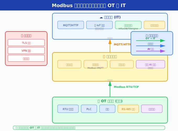
Understanding the architecture is the prerequisite for mastering the application of Modbus in the Industrial Internet of Things (IIoT). The data flow in traditional factories is divided into five layers: the field device layer (sensors/actuators), the control layer (PLC/DCS), the monitoring layer (SCADA/HMI), the management layer (MES), and the enterprise layer (ERP). In this classic Purdue model, the Modbus protocol is mainly active in the first three layers, with data passing through protocol and semantic conversions layer by layer as it moves upwards.
The emergence of the IIoT has disrupted this layer-by-layer transmission architecture. Through edge computing gateways, on-site Modbus data can directly "leapfrog" the intermediate layers and enter the cloud platform directly in the form of MQTT or other IoT protocols. This flattened architecture significantly reduces data latency and enhances data density, enabling the implementation of big data analysis and AI algorithms in industrial scenarios.
The modern three-layer architecture of IIoT
| levels | main devices/systems | communication protocols | data characteristics |
|---|---|---|---|
| edge layer (Edge) | PLC, sensors, edge gateways | Modbus RTU/TCP, OPC UA | high-frequency, real-time, local closed-loop |
| platform layer (Fog/Platform) | IoT platform, time-series database, rule engine | MQTT, HTTP, AMQP | medium frequency, structured, persistent |
| application layer (Cloud/App) | BI dashboard, AI model, digital twin | HTTPS, WebSocket, gRPC | aggregation, analysis, visualization |
In this architecture,Modbus edge computinggateway plays a pivotal role - it serves as a bridge between the OT world and the IT world, responsible for Modbus data acquisition, protocol conversion, data preprocessing, and secure transmission.
The core challenge of Modbus data acquisition
Engineers face multiple challenges when integrating Modbus data into the Industrial Internet of Things (IIoT). Understanding these challenges is a prerequisite for designing appropriate solutions.
Challenge One: Large and Distributed Data Volume
A medium-sized factory may have hundreds of Modbus devices, each with tens to hundreds of registers. Taking 200 frequency converters as an example, each reads 10 key parameters (frequency, current, voltage, temperature, alarm codes, etc.), with each polling taking about 30ms, and a complete round taking 6 seconds. To achieve second-level data collection, parallelization strategies and multi-serial port solutions are required.
Challenge Two: Protocol Differences and Heterogeneous Integration
Although field devices are all based on the Modbus protocol, implementations from different vendors vary - different address mapping methods, byte orders, and data formats (integers/floating-point numbers/BCD codes). These differences can be handled one by one in manual configuration, but in large-scale IIoT deployments, they must be addressed through automated and standardized configuration management.
Challenge Three: Network Reliability
The network environment in factory workshops is far worse than that in data centers - electromagnetic interference, high temperatures, and vibrations all affect network stability. Although Modbus RTU (RS-485) has strong anti-interference capabilities, in complex wiring with long distances and multiple nodes, issues such as terminal resistance matching, grounding loops, and common-mode interference still occur frequently.
Challenge Four: Balancing Real-time Performance and Throughput
Modbus RTU is a typical request-response protocol, where the master station can only handle one request at a time. In scenarios with a large number of slave stations, the polling cycle is long, making it difficult to meet high-frequency data collection requirements. Solutions include multi-serial port parallelism, replacing RTU with Modbus TCP, and introducing edge-side data caching and batch reporting mechanisms.
Selection and Deployment of Edge Computing Gateways
Edge computing gateways are the most critical hardware nodes in the IIoT data architecture. Choosing the right gateway directly determines the system's reliability, scalability, and maintenance costs. The following is aboutModbus edge computingCore selection elements of the gateway.
Hardware specification requirements
| Parameters | Minimum requirements | Recommended configuration | Description |
|---|---|---|---|
| CPU | ARM Cortex-A7 single-core | Cortex-A72 quad-core or above | Stronger computing power is required to support edge AI inference |
| Memory | 256MB | 1-2GB | Run Node-RED + MQTT Broker + data caching |
| storage | 4GB eMMC | 16-32GB eMMC + SD card expansion | local caching of offline data |
| number of serial ports | 1×RS-485 | 2-4×RS-485 (isolated) | multi-bus parallel acquisition |
| Ethernet | 1×10/100M | 2×10/100/1000M | WAN + LAN isolation |
| 4G/5G | Optional | Built-in CAT4/CAT1 | Remote site wireless access |
| Operating temperature | -20°C~70°C | -40°C~85°C | Outdoor/extreme conditions |
Comparison of mainstream edge gateway products
| Product | Platform | Modbus support | MQTT support | Applicable scenarios |
|---|---|---|---|---|
| Advantech ECU-1251 | WISE-EdgeLink | RTU/TCP dual mode | Native support | Small and medium-sized factories |
| MOXA UC-8100 | ThingsPro suite | RTU/TCP dual mode | Built-in Broker | Harsh Environment |
| Huawei AR650 | Edge Computing IEF | Protocol Plug-in Support | Function Calculation Support | Enterprise-level Deployment |
| Raspberry Pi + Node-RED | Open-source Customization | node-red-contrib-modbus | mosquitto/EMQX | Prototype Verification/Small Scale |
| InHand IG902 | Device Manager | RTU/TCP Dual Mode | Built-in Broker | Cost-effective Choice |
Deployment Best Practices
- In-situ Collection Principle: Deploy edge gateways as close as possible to Modbus devices, shortening the RS-485 bus length (recommended not to exceed 200 meters) to reduce wiring costs and interference.
- Isolation Protection: RS-485 ports must be optoelectronically isolated to prevent common-mode voltage damage to the gateway. When multiple devices share a single bus, ensure all devices are grounded together or use isolated RS-485 repeaters.
- Local Cache and Resumable Transmission: Configure the local storage caching strategy of the edge gateway to temporarily store data locally when the network connection to the cloud platform is interrupted; automatically resume transmitting historical data after the network is restored to ensure data is not lost.
- OTA Remote Upgrade: Choose gateway products that support OTA (Over-The-Air) firmware upgrades to avoid the need for on-site operations due to configuration changes.
Detailed Explanation of Modbus → MQTT Protocol Conversion
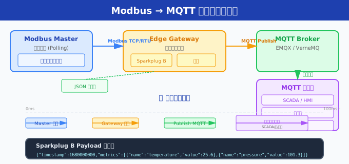
Modbus MQTTProtocol conversion is the core technical aspect of the entire IIoT data architecture. Modbus is a request-response polling protocol, while MQTT is an asynchronous message protocol based on publish-subscribe. The conversion between the two involves not only format mapping but also a fundamental shift in communication paradigm.
Conversion Architecture Design
// Modbus → MQTT 协议转换架构

┌─────────────┐     Modbus RTU/TCP      ┌────────────────┐
│ Modbus 设备  │◄──────────────────────►│ 协议转换引擎    │
│ (PLC/传感器)  │                        │                │
└─────────────┘                        │ ┌────────────┐ │
                                       │ │ 轮询调度器   │ │
┌─────────────┐                        │ ├────────────┤ │
│ Modbus 设备  │◄──────────────────────►│ │ 数据映射表   │ │
│ (变频器/仪表) │                        │ ├────────────┤ │
└─────────────┘                        │ │ 格式转换器   │ │
                                       │ ├────────────┤ │
                                       │ │ MQTT 客户端  │ │
                                       │ └────────────┘ │
                                       └───────┬────────┘
                                               │ MQTT (TCP/SSL)
                                               ▼
                                       ┌────────────────┐
                                       │  MQTT Broker    │
                                       │ (EMQX/Mosquitto)│
                                       └───────┬────────┘
                                               │
                                               ▼
                                       ┌────────────────┐
                                       │  IoT 云平台     │
                                       │  数据消费方     │
                                       └────────────────┘
Sparkplug B Specification: Industrial MQTT Standard
Eclipse Sparkplug B is an industrial IoT communication specification built on MQTT, specifically addressing the lack of data context in traditional MQTT in industrial scenarios. Sparkplug B defines a unified data encoding format (Google Protocol Buffers), topic namespace (spBv1.0/groupID/msgType/edgeNodeID/deviceID), and session state management mechanism (birth/death messages).
After using the Sparkplug B specification, the semantics of Modbus data will not be lost during transmission. For example, the temperature value (unit: 0.1°C) of Modbus register 40001, after being converted into a Sparkplug B message, will carry complete metadata: Metric Name (Temperature), Data Type (Float), Engineering Unit (°C), Timestamp, and quality flag.
Core Conversion Logic Implementation
// Python 伪代码:Modbus RTU → MQTT 桥接核心逻辑
import minimalmodbus
import paho.mqtt.client as mqtt
import json
import time

# Modbus 配置
instrument = minimalmodbus.Instrument('/dev/ttyUSB0', 1)
instrument.serial.baudrate = 9600
instrument.serial.bytesize = 8
instrument.serial.parity = 'E'
instrument.serial.stopbits = 1

# MQTT 配置
mqtt_client = mqtt.Client("modbus_gateway_01")
mqtt_client.connect("mqtt-broker.local", 1883)

# 寄存器映射表:{Modbus地址: (MQTT主题, 数据转换函数)}
register_map = {
    0:  ("plant1/pump1/temperature", lambda v: v / 10.0),
    1:  ("plant1/pump1/pressure",    lambda v: v / 100.0),
    2:  ("plant1/pump1/flow_rate",   lambda v: v / 100.0),
    3:  ("plant1/pump1/current",     lambda v: v / 10.0),
    10: ("plant1/pump1/status",      lambda v: v),  # 位状态
}

while True:
    for addr, (topic, transform) in register_map.items():
        try:
            raw_value = instrument.read_register(addr)
            converted = transform(raw_value)
            payload = json.dumps({
                "value": converted,
                "timestamp": int(time.time() * 1000),
                "quality": 0  # 0=Good
            })
            mqtt_client.publish(topic, payload, qos=1)
        except Exception as e:
            print(f"Error reading register {addr}: {e}")
    time.sleep(1)  # 采集间隔
Node-RED Implementation of Modbus Data Flow Processing
Node-RED is a visual data flow programming tool based on Node.js, widely used in the industrial IoT field. Through the node-red-contrib-modbus node, Modbus data collection, conversion, and distribution can be achieved without writing code. Here is a complete Flow example.
Complete Flow: Modbus Data Collection → Processing → Storage → Cloud Uploading
// Node-RED Flow JSON(导入即用)
[
    {
        "id": "modbus-read",
        "type": "modbus-read",
        "name": "读取水泵参数",
        "topic": "pump",
        "showStatusActivities": false,
        "showErrors": true,
        "unitid": 1,
        "dataType": "HoldingRegister",
        "adress": 0,       // 起始地址(对应 40001)
        "quantity": 6,     // 读取 6 个寄存器
        "rate": 1000,      // 每 1000ms 读取一次
        "rateUnit": "ms",
        "delayOnStart": true,
        "wires": [["format"]]  // 连接到数据处理节点
    },
    {
        "id": "format",
        "type": "function",
        "name": "数据格式化与转换",
        "func": "// 将 Modbus 寄存器数组转换为结构化对象n"
               + "const data = msg.payload;n"
               + "const temperature = data[0] / 10.0;  // 0.1°C 分辨率n"
               + "const pressure    = data[1] / 100.0;  // 0.01MPa 分辨率n"
               + "const flow        = data[2] / 100.0;  // 0.01m³/h 分辨率n"
               + "const current     = data[3] / 10.0;   // 0.1A 分辨率n"
               + "const alarm       = data[4];          // 报警码n"
               + "const runtime     = data[5];          // 运行时间(小时)nn"
               + "msg.payload = {n"
               + "    device: 'pump_01',n"
               + "    timestamp: Date.now(),n"
               + "    metrics: {n"
               + "        temperature: temperature,n"
               + "        pressure: pressure,n"
               + "        flow: flow,n"
               + "        current: current,n"
               + "        alarm: alarm,n"
               + "        runtime: runtimen"
               + "    }n"
               + "};n"
               + "return msg;",
        "outputs": 1,
        "wires": [["alarm-check", "mqtt-out", "influxdb-out"]]
    },
    {
        "id": "alarm-check",
        "type": "function",
        "name": "报警判断",
        "func": "const alarm = msg.payload.metrics.alarm;n"
               + "if (alarm !== 0) {n"
               + "    msg.payload = {n"
               + "        device: msg.payload.device,n"
               + "        alarm_code: alarm,n"
               + "        timestamp: msg.payload.timestamp,n"
               + "        severity: alarm > 10 ? 'HIGH' : 'LOW'n"
               + "    };n"
               + "    return msg;n"
               + "}n"
               + "return null;  // 无报警时不发送",
        "wires": [["mqtt-alarm"]]
    },
    {
        "id": "mqtt-out",
        "type": "mqtt out",
        "name": "MQTT 数据上报",
        "topic": "plant/pump/data",
        "qos": "1",
        "retain": "false",
        "broker": "local-mqtt"
    },
    {
        "id": "mqtt-alarm",
        "type": "mqtt out",
        "name": "MQTT 报警上报",
        "topic": "plant/pump/alarm",
        "qos": "2",
        "retain": "true",
        "broker": "local-mqtt"
    },
    {
        "id": "influxdb-out",
        "type": "influxdb out",
        "name": "InfluxDB 存储",
        "influxdb": "local-influxdb",
        "database": "pump_metrics",
        "measurement": "pump_data",
        "retentionPolicy": "autogen"
    }
]
High-Performance Polling Strategy
When managing dozens or even hundreds of Modbus slaves, Node-RED's serial polling may become a performance bottleneck. The following optimization strategies can improve polling efficiency by 3-10 times: use multiple Modbus read nodes connected to different serial ports for parallel collection; set different polling frequencies for devices of different importance (critical devices at 500ms, general devices at 5s); use Link nodes to aggregate data into a unified processing pipeline; introduce data change detection (trigger subsequent processing only when data changes exceed a deadband threshold), reducing invalid data transmission and storage.
Mainstream cloud platform access solution
Will Modbus cloud platformData access is the last mile in IIoT deployment. Below are complete access solutions for the three major mainstream IoT platforms.
Access to Alibaba Cloud IoT Platform
Alibaba Cloud IoT Platform offers both enterprise-level and public instances, supporting both direct device connection and gateway proxy access methods. Modbus devices are typically accessed through edge gateways (Link IoT Edge). Link IoT Edge has a built-in Modbus driver, enabling device modeling, driver configuration, and point mapping in the cloud, achieving zero-code Modbus data upload to the cloud.
// 阿里云 IoT 设备影子 JSON(Modbus 数据模型示例)
{
    "deviceName": "pump_station_01",
    "productKey": "a1xxxxxxxx",
    "properties": {
        "pump1_temp": {
            "value": 42.5,
            "time": 1688000000000,
            "source": "modbus_40001",
            "scale": 0.1,
            "unit": "°C"
        },
        "pump1_pressure": {
            "value": 0.35,
            "time": 1688000000000,
            "source": "modbus_40002",
            "scale": 0.01,
            "unit": "MPa"
        }
    }
}
Access to Huawei Cloud IoT Platform
Huawei Cloud IoTDA (Device Access Service) accesses Modbus devices through edge IEF or a built-in protocol adaptation framework. Its unique advantage lies in its deep integration with Huawei Cloud's ModelArts AI platform, allowing directly using collected Modbus data for model training and inference. Through IoTDA's rule engine, data flow rules can be defined to route Modbus data in real time to multiple Huawei Cloud services such as DIS (Data Access Service), OBS (Object Storage), and FunctionGraph (Function Computing).
Access to ThingsBoard Open Source Platform
ThingsBoard is currently the most popular open source IoT platform, offering community, professional, and cloud-hosted versions. Through the ThingsBoard Gateway component, data collection and reporting from Modbus devices can be achieved without any code. The Gateway defines Modbus connectors through JSON configuration files, including serial port parameters, device slave address, register mapping, and data conversion rules.
{
    "master": {
        "slaves": [
            {
                "host": "192.168.1.100",
                "port": 502,
                "type": "tcp",
                "method": "socket",
                "timeout": 35,
                "byteOrder": "BIG",
                "wordOrder": "BIG",
                "retries": true,
                "retryOnEmpty": true,
                "retryOnInvalid": true,
                "pollPeriod": 5000,
                "unitId": 1,
                "deviceName": "Pump Station 01",
                "sendDataOnlyOnChange": false,
                "attributes": [],
                "timeseries": [
                    {
                        "tag": "temperature",
                        "address": 0,
                        "type": "4x",        // 保持寄存器
                        "registerCount": 1,
                        "multiplier": 0.1,
                        "unit": "°C"
                    },
                    {
                        "tag": "pressure",
                        "address": 1,
                        "type": "4x",
                        "registerCount": 1,
                        "multiplier": 0.01,
                        "unit": "MPa"
                    }
                ]
            }
        ]
    }
}
Data Storage Solution
Modbus devices generate typical time series data - sequences of time-stamped numerical values, featuring high-frequency writes, time range queries, data compression, and downsampling. Choosing the right time series database is crucial for ensuring IIoT system performance.
Comparison between InfluxDB and TDengine
| Features | InfluxDB | TDengine |
|---|---|---|
| Development Language | Go | C |
| Storage Engine | Self-developed TSM Tree | Self-developed Columnar Storage |
| Write Performance | Medium | Extremely High (10x+ compared to InfluxDB) |
| Query Performance | Okay | Excellent (optimized for super tables) |
| Compression Ratio | 5-10x | 10-20x |
| SQL Compatibility | SQL-like (InfluxQL/Flux) | Standard SQL extension |
| Cluster support | Paid version support | Open source support |
| Community activity | Very active | Rapid growth |
| Localization | No | Yes (preferred for domestic substitution) |
| Cost of 100,000 points/second | Relatively high | Lower |
TDengine Super Table Design Example
-- 创建超级表:一个水泵站对应一张子表,统一 Schema 管理
CREATE STABLE pump_metrics (
    ts          TIMESTAMP,
    temperature FLOAT,
    pressure    FLOAT,
    flow_rate   FLOAT,
    current     FLOAT,
    power       FLOAT,
    alarm_code  INT
) TAGS (
    station_id  INT,
    pump_id     INT,
    location    BINARY(64),
    rated_power FLOAT
);

-- 创建子表(每个设备一张)
CREATE TABLE pump_s01_p01 USING pump_metrics
TAGS (1, 1, '一号泵站-1号泵', 37.0);

CREATE TABLE pump_s01_p02 USING pump_metrics
TAGS (1, 2, '一号泵站-2号泵', 55.0);

-- 查询:所有 1 号泵站中温度超过 45°C 的水泵
SELECT station_id, pump_id, temperature, ts
FROM pump_metrics
WHERE temperature > 45.0
  AND station_id = 1
  AND ts >= NOW - 1h;

-- 降采样:最近 24 小时每 5 分钟的平均温度
SELECT AVG(temperature), AVG(pressure)
FROM pump_metrics
WHERE ts >= NOW - 24h
INTERVAL(5m);
Edge AI: Anomaly Detection of Modbus Data
The ultimate value of Industrial Internet of Things (IIoT) lies not only in data collection and monitoring, but also in intelligent decision-making based on data. Deploying lightweight AI models at the edge enables real-time anomaly detection of Modbus data, marking a leap from "post-event alarming" to "pre-event warning".
Statistical Methods: 3σ Principle and Sliding Window
The simplest anomaly detection method is based on statistical principles. For stable operating condition data (such as the current of a pump running at constant speed), the 3σ principle (Pareto criterion) can be used to detect significant outliers. Specifically, a sliding window (such as the most recent 100 data points) is maintained, and the mean and standard deviation of the data within the window are calculated. When a new data point deviates from the mean by more than 3 times the standard deviation, it is determined to be anomalous.
// Python: 滑动窗口 + 3σ 异常检测(边缘网关本地执行)
import numpy as np
from collections import deque

class AnomalyDetector:
    def __init__(self, window_size=100, sigma=3.0):
        self.window = deque(maxlen=window_size)
        self.sigma = sigma

    def check(self, value):
        self.window.append(value)
        if len(self.window)  threshold_upper or value < threshold_lower
        return is_anomaly, {
            'mean': mean, 'std': std,
            'upper': threshold_upper,
            'lower': threshold_lower
        }

# 使用示例:监控 Modbus 读取的温度值
temp_detector = AnomalyDetector(window_size=50, sigma=3.0)
vibration_detector = AnomalyDetector(window_size=100, sigma=4.0)
Rule-Based Composite Judgment
Pure value anomaly detection is prone to false alarms. A more practical approach is to combine multiple Modbus data points for composite judgment. For example, the early characteristics of pump bearing failure are the simultaneous occurrence of "increased vibration + increased temperature + increased current". This multi-dimensional joint judgment can significantly reduce the false alarm rate.
Security Architecture Design
The security issues of IIoT cannot be ignored. The Modbus protocol itself does not have any security mechanisms - no identity authentication, no data encryption, and no integrity verification (CRC only checks errors but does not prevent tampering). In the IIoT architecture, multiple layers of security mechanisms must be employed to compensate for the deficiencies of the protocol itself.
Defense-in-Depth Four-Layer Model
| Hierarchy | Security Measures | Description |
|---|---|---|
| Physical Isolation Layer | Gap, One-Way Isolation Device | Physical Isolation between OT and IT Networks |
| Network Transmission Layer | TLS 1.3, IPSec VPN | MQTT Communication Mandates TLS Encryption |
| Identity Authentication Layer | X.509 Certificate, Token Authentication | Device Mutual Authentication to Prevent Impersonation |
| Application Audit Layer | Operation logs, traffic audit | Full-chain traceability |
MQTT TLS encryption configuration
// EMQX Broker 配置:启用 TLS + 客户端证书认证
listeners.ssl.default {
    bind = "0.0.0.0:8883"
    ssl_options {
        keyfile = "/etc/emqx/certs/server.key"
        certfile = "/etc/emqx/certs/server.crt"
        cacertfile = "/etc/emqx/certs/ca.crt"
        verify = verify_peer       # 强制客户端证书验证
        fail_if_no_peer_cert = true
        versions = [tlsv1.3, tlsv1.2]
        ciphers = [
            "TLS_AES_256_GCM_SHA384",
            "TLS_AES_128_GCM_SHA256",
            "ECDHE-ECDSA-AES256-GCM-SHA384"
        ]
    }
}

// 边缘网关 MQTT TLS 客户端配置
mqtt_client.tls_set(
    ca_certs="/etc/gateway/certs/ca.crt",
    certfile="/etc/gateway/certs/client.crt",
    keyfile="/etc/gateway/certs/client.key",
    cert_reqs=ssl.CERT_REQUIRED,
    tls_version=ssl.PROTOCOL_TLSv1_3
)
mqtt_client.connect("mqtt-broker.local", 8883)
Practical case: Remote monitoring system for water pump stations
Below is a real-liferemote monitoring system for water pump stationswith a complete architecture case, demonstrating the full-stack implementation of Modbus industrial IoT technology.
Project background and requirements
- Coverage: 12 decentralized water pump stations under a water utility company, with the longest distance of 80 kilometers
- Equipment types: Each station has 2-4 water pumps (including frequency converters), flowmeters, pressure transmitters, and level gauges
- Protocol: All devices communicate via Modbus RTU (RS-485) with a unified baud rate of 9600
- Collection frequency: Key data (frequency, current, pressure) at 1Hz, secondary data (accumulated quantity, temperature) at 0.1Hz
- Core Requirements: Remote Real-Time Monitoring, Historical Data Query, Anomaly Alerts, Operation and Maintenance Reports, Mobile Access
System Architecture Design
// 水泵站远程监控系统架构

泵站现场 (12 个站点)
┌──────────────────────────────────────┐
│  PLC (台达 DVP) ◄── RS-485 ──► 变频器 │
│       │◄────────── RS-485 ──► 流量计 │
│       │◄────────── RS-485 ──► 压力变送器 │
│       │◄────────── 4-20mA ──► 液位计 │
│       ▼                              │
│  研华 ECU-1251 边缘网关                │
│  ├─ Modbus 多站轮询                   │
│  ├─ Node-RED 数据预处理               │
│  ├─ 本地 7 天数据缓存                  │
│  ├─ MQTT (TLS) → 云平台              │
│  └─ 4G 无线通信                       │
└──────────────────────────────────────┘

云平台层 (华为云)
┌──────────────────────────────────────┐
│  IoTDA ──► Kafka ──► Flink 流计算    │
│                    ──► TDengine 存储  │
│                    ──► 告警规则引擎    │
│                                     │
│  应用服务                            │
│  ├─ Spring Boot 后端 API             │
│  ├─ Vue.js 前端监控大屏               │
│  └─ 微信小程序移动端                  │
└──────────────────────────────────────┘
Key Implementation Points
- Address Mapping Standardization: Establish a unified Modbus address mapping specification, with 12 pump stations adopting the same register allocation scheme (e.g., fixed storage of core parameters such as pressure and flow in 40001-40010), simplifying gateway configuration and subsequent maintenance.
- Disconnection Resume Mechanism: Configure a local SQLite database on the edge gateway, automatically switching to local storage mode when the network is interrupted. After the network is restored, all historical data will be uploaded in chronological order to ensure zero data loss.
- Hierarchical Alarm Strategy: Level 1 alarms (equipment downtime, pressure overrun) are pushed in real-time to the operation and maintenance personnel's mobile phones; Level 2 alarms (high temperature, increased vibration) are sent to the monitoring screen; Level 3 alarms (minor parameter deviations) are only recorded for trend analysis.
- Data Quality Monitoring: Establish a data quality indicator system to monitor the collection success rate, communication delay, and numerical validity of each Modbus data point. When data quality decreases, an operation and maintenance work order is automatically triggered.
Future Trends and Outlook
Although the Modbus protocol has a history of over 40 years, it still thrives in the era of Industrial Internet of Things. Here are several notable technological trends.
OPC UA over Modbus
OPC UA (Unified Architecture) is the core communication standard for Industry 4.0, providing information modeling, secure communication, and semantic interoperability. An increasing number of devices are starting to support both Modbus and OPC UA. In practical architectures, Modbus is responsible for low-cost interconnection at the field device level, while OPC UA provides standardized data interfaces to upper-level systems. Protocol converters (Modbus → OPC UA) in edge gateways become key components.
TSN (Time-Sensitive Networking) and Modbus TCP
TSN is a set of Ethernet standards defined by the IEEE 802.1 task force, aiming to provide deterministic latency for industrial Ethernet. Modbus TCP over TSN will become an important technological route for future real-time control scenarios. TSN solves the problem of latency uncertainty in standard Ethernet, enabling Modbus TCP to be applied in scenarios with extremely high real-time requirements such as motion control.
5G + Modbus Wireless
Among the three major scenarios of 5G (eMBB for high bandwidth, uRLLC for low latency, and mMTC for massive connectivity), uRLLC provides the possibility of wirelessization for industrial control. Carrying Modbus TCP on a 5G network to achieve wireless interconnection of field devices can eliminate wiring costs and improve production line flexibility. 5G LAN (Local Area Network) technology can even directly replace industrial Ethernet to achieve wireless Modbus TCP communication between PLCs and between PLCs and edge gateways.
FAQs
Q1: What is the upper limit of polling speed for Modbus gateways? How can it be improved?
The polling speed of Modbus RTU on a single RS-485 bus is limited by the following factors: baud rate (approximately 1ms/character at 9600 bps), message length (read and write operations require approximately 8-25 bytes), slave response time (ranging from 1-50ms), and inter-frame spacing (3.5 character times).
Q2: Should MQTT Broker be deployed at the edge or in the cloud?
It is recommended to adopt a two-tier Broker architecture: deploy a lightweight MQTT Broker (such as Mosquitto or NanoMQ) on the edge side, responsible for data aggregation from all local Modbus gateways and data distribution to local applications (such as HMI, local monitoring screens); deploy an enterprise-level MQTT Broker (such as an EMQX cluster) in the cloud, synchronizing data with the edge Broker through the MQTT Bridge mode. The advantage of this architecture lies in: local monitoring remains unaffected when the cloud is disconnected; only one MQTT connection is required between the edge and the cloud, reducing network overhead; the cloud Broker can uniformly manage data routing and permissions across all sites.
Q3: How reliable is Node-RED in industrial scenarios?
Node-RED performs well in prototype verification and small-scale production environments (with fewer than 50 devices). However, in large-scale industrial deployments (with 100+ devices and 10,000+ data points), the following issues need to be considered: the CPU bottleneck of single-process Node.js, which can be addressed by using cluster mode or splitting multiple Node-RED instances; the loss of Flow state after restart, which requires external storage (such as SQLite) to achieve state persistence; and memory leaks that may occur after long-term operation, which suggest using the PM2 process management tool for automatic restart and health monitoring. For critical task scenarios, it is recommended to use commercial edge computing platforms (such as Advantech WISE-EdgeLink, MOXA ThingsPro) instead of purely open-source self-built solutions.
Q4: How to perform data tracing in reports after Modbus data is uploaded to the cloud?
The key to data tracing is to retain the contextual information of the original Modbus data. When reporting data, each data point should carry the following metadata: device unique identifier (Device ID), Modbus register address, raw value, converted engineering value, collection timestamp (accurate to milliseconds), and data quality flag (Good/Bad/Uncertain). Time-series databases such as TDengine support creating sub-tables with device IDs as tags. During querying, flexible data tracing and comparative analysis can be performed by device, time period, and register address.
Conclusion
The practice of Modbus Industrial Internet of Thingstells us that the vitality of a technology lies not in its apparent advanced level, but in its ability to solve problems in real-world scenarios. With its minimalist design, wide device support, and zero licensing cost, the Modbus protocol has become a natural bridge connecting the industrial OT world with the IT world. ThroughModbus edge computinggateways,Modbus MQTTprotocol bridges, and reasonableModbus cloud platformarchitecture design, we can fully enjoy the intelligent capabilities brought by the Internet of Things and cloud computing while retaining the simple and reliable characteristics of Modbus.
Over four decades have passed since Modicon released the Modbus protocol in 1979. During these four decades, countless communication protocols have emerged and faded away, yet Modbus remains active in hundreds of millions of industrial devices worldwide.IIoT ModbusThis is not the end of Modbus, but its rebirth in the era of intelligence. We hope that every reader can, with the guidance of modbus.cn, apply this classic protocol to broader industrial IoT scenarios.
We recommend continuing to read the related series of articles onmodbus.cn:
- Complete Guide to Selecting Modbus Edge Computing Gateways
- Practical Conversion from Modbus to MQTT Sparkplug B Protocol
- Node-RED Modbus Data Visualization Tutorial
- TDengine + Modbus Industrial IoT Data Storage Solution
- Practical Guide to Programming Modbus in Mainstream PLCs
- Industrial IoT Modbus Security Protection System
On the road of technology, modbus.cn walks with you.


Leave a Reply