

The Modbus function code is an important component of Modbus message frames (messages) and serves as the basis for communication transaction processing in the Modbus protocol.
Disconnect it from other devices in the network without returning a response
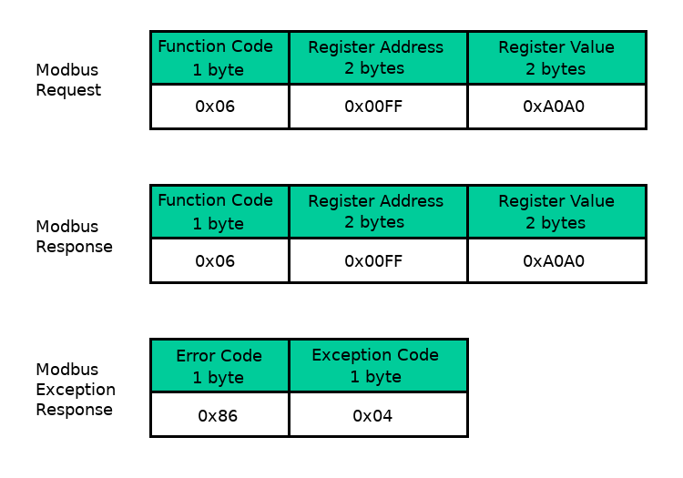
Modbus Function code occupies one byte, The range of values is 1~127(i.e 0x01~0x7F) . at the same time, Use function code + 0x80 Indicate abnormal stateThat is 129~255 Representing exception codes.
in Modbus In the standard protocol, There are a total of three categories specified Modbus function code.
- Public Function Code
- Clearly defined functional codes;
- Ensure uniqueness;
- from Modbus Association confirmation, And provide publicly available documents;
- Can conduct consistency testing;
- Including function codes defined by the protocol and reserved function codes for future use.
- User defined function code
- There are two user-defined function code areas, They are respectively. 65
72 and 100110; - user-defined, No guarantee of uniqueness.
- There are two user-defined function code areas, They are respectively. 65
- Retain function code
- Retaining the function code is due to historical legacy reasons, The functional codes currently used on traditional products of certain companies are not considered for public use.
This tutorial mainly introduces common function codes, The following table shows Modbus Partial public function codes in the agreement.
| Code | Name | English | register PLC address | Bit/word operation | number of operations |
|---|---|---|---|---|---|
| 01 | Read coil status | Read Coils | 00001~09999 | bit manipulation | Single or multiple |
| 02 | Read discrete input states | Read Discrete Inputs | 10001~19999 | bit manipulation | Single or multiple |
| 03 | Read and hold register | Read Holding Registers | 40001~49999 | Word operation | Single or multiple |
| 04 | Read input register | Read Input Registers | 30001~39999 | Word operation | Single or multiple |
| 05 | Write a single coil | Write Single Coil | 00001~09999 | bit manipulation | single |
| 06 | Write a single hold register | Write Single Register | 40001~49999 | Word operation | single |
| 15 | Write multiple coils | Write Multiple Coils | 00001~09999 | bit manipulation | multiple |
| 16 | Write multiple hold registers | Write Multiple Registers | 40001~49999 | Word operation | multiple |
The operation of function codes can be divided into two types:
- bit manipulation —— The smallest unit is one (bit) , Including the function code for reading coil status 01, Read discrete input status function code 02, Write a single coil function code 05 Write multiple coil function codes 15;
- Word operation —— The minimum unit is two bytes, Including read and hold register function codes 03, Read input register function code 04, Write a single hold register function code 06 Write multiple hold register function codes 16.
function code
0x01 Read coil/discrete output values
- This function code is used to read the status of the coil or discrete output from the device, That is, each DO (Discrete Output, Discrete outputof ON/OFF Status.
- The message frame specifies the starting address and number of coils to be read.
- The starting address is from 2 Composed of bytes, The range of values is 0x0000 to 0xFFFF.
- The number of coils is determined by 2 Composed of bytes, The range of values is 0x0001 to 0x07D0 (That is, decimal system 1~2000) .
- Note, in Modbus According to the agreement PDU In the middle,Require all coil or register addresses to be from 0 Start calculation.
0x02 Read discrete input values
- This function code is used to read discrete inputs from the deviceThat is DI (Discrete Inputof ON/OFF Status.
- The message frame specifies the starting address and number of discrete input registers to be read, Readable 1~2000 A continuous discrete input state.
- If receiving a request from the master device, reply with a function code 02, And return the current state of each variable as a discrete input (If returned DI The quantity is not 8 Integer multiples of, Will be used 0 Fill in the remaining bits of the last data byte) .
- The starting address is from 2 Composed of bytes, The range of values is 0x0000 to 0xFFFF.
- The quantity of discrete quantities is determined by 2 Composed of bytes, The range of values is 0x0001 to 0x07D0 (That is, decimal system 1~2000) , Can be read at most once 2000 A discrete input state value.
0x03 Read and hold register values
- This function code is used to read the contents of the device's hold register, Broadcast mode not supported.
- The message frame specifies the starting address and number of hold registers to be read, The specific content and meaning of each address in the register are determined by the device developer themselves.
- The starting address is from 2 Composed of bytes, The range of values is 0x0000 to 0xFFFF.
- The number of registers is determined by 2 Composed of bytes, The range of values is 0x0001 to 0x007D (That is, decimal system 1~125) , Can be read continuously at most once 125 A register value.
- Note, Modbus The keep register and input register are written in words (Word) As a basic unit (1Word equal to 2Bytes) . Therefore, Pay attention to byte order when reading (endianness) Problem.
0x04 Read input register values
- This function code is used to read the contents of the input register from the device, Broadcast mode not supported. (And) 03 Similar function codes)
- The message frame specifies the starting address and number of input registers to be read, The specific content and meaning of each address in the input register are determined by the device developer themselves.
- The starting address is from 2 Composed of bytes, The range of values is 0x0000 to 0xFFFF.
- The number of registers is determined by 2 Composed of bytes, The range of values is 0x0001 to 0x007D (That is, decimal system 1~125) , Can be read continuously at most once 125 A register value.
- Attention should also be paid to byte order issues.
0x05 Write a single coil/single discrete output
- This function code is used to register a single coil (Or discrete output) set to ON or OFF, Support broadcast mode.
- In broadcast mode, The values of the same address for all slave devices will be uniformly modified.
- The message frame specifies the coil address that needs to be changed and the set state value.
- The starting address is from 2 Composed of bytes, The range of values is 0x0000 to 0xFFFF.
- target data (Namely, querying the message ON/OFF Status) Designated by constants of message data fields, 0xFF00 express ON Status, 0x0000 express OFF Status, All other values are illegal.
- Note, in Modbus According to the agreement PDU In the middle,Require all coil or register addresses to be from 0 Start calculation.
0x06 Write a single hold register
- This function code is used to update the value of a single hold register from the device, Support broadcast mode.
- In broadcast mode, The values of the same address for all slave devices will be uniformly modified.
- The message frame needs to specify the device address, as well as the address and set value of the hold register that needs to be changed.
- The starting address is from 2 Composed of bytes, The range of values is 0x0000 to 0xFFFF.
- Change target data by 2 Composed of bytes, The range of values is 0x0000 to 0xFFFF.
- Keep registers in words (Word) As a basic unit, Attention should be paid to the byte order of the target data when writing.
0x08 Diagnostic function
- This function code is only used for serial links, Mainly used to detect communication failures between master and slave devices, Or detect various internal faults of the device, This feature does not support broadcasting.
- The query message needs to specify the device address, function code (Modbus Command) And sub function codes (Diagnostic Sub-function) . among which, The sub function code field is 2 bytes, Used to distinguish between various diagnostic types.
- In a normal response message, Reply the original function code and sub function code from the device.
commonly used Modbus The definition of diagnostic sub function codes is as follows:
| function code | Sub function code | Description | Instructions |
|---|---|---|---|
| 08 | 00 (0x00) | Return Data Query (Loop-back) | Return the query message as it is |
| 08 | 01 (0x01) | Restart Communications | Used for initializing and restarting slave devices among which, Message fields 0x00, 0x00 Maintain event records 0xFF, 0x00 Indicates clearing event records |
| 08 | 02 (0x02) | Return Diagnostic Register | Return the contents of the diagnostic register |
| 08 | 03 (0x03) | Change ASCII Input Delimiter | |
| 08 | 04 (0x04) | Force Listen Only Mode | Force addressed slave devices to enter listen only mode Disconnect it from other devices in the network, No response returned |
| 08 | 10 (0x0A) | Clear Counters and Diagnostic Registers | Clear counters and diagnostic registers |
| 08 | 11 (0x0B) | Return Bus Message Count | Return the bus message count value |
| 08 | 12 (0x0C) | Return Bus Communication Error Count | Return to bus communication CRC Error count |
| 08 | 13 (0x0D) | Return Bus Exception Error Count | Return bus exception count |
| 08 | 14 (0x0E) | Return Slave Message Count | Return the number of messages received from the station device |
| 08 | 15 (0x0F) | Return Slave No Response Count | Return the number of messages from the slave device that did not receive a response |
| 08 | 16 (0x10) | Return Slave NAK Count | |
| 08 | 17 (0x11) | Return Slave Busy Count | Return the number of busy response messages from the slave device |
| 08 | 18 (0x12) | Return Bus Character Overrun Count | Return the number of messages with bus characters exceeding the limit |
| 08 | 19 (0x13) | Return IOP Overrun Count (884) | |
| 08 | 20 (0x14) | Clear Overrun Counter and Flag (884) |
0x0B Get communication event counter
- This function code is mainly used to obtain the status word and event count values from the device communication counter, Broadcast mode not supported.
- It is possible to read the communication event count values before and after the communication message, To determine if the device is processing messages properly.
- For situations where message processing and transmission are completed normally, Event counter increases 1; And for abnormal responses, Polling command or read event counter(i.e 0x0B function code) The occasion, The counter remains unchanged.
- Through 0x08 In the diagnostic function 0x01 Sub functions and 0x0A sub-function, Can reset event register.
0x0C Retrieve communication event records
- This function code is mainly used to obtain status words from the device, Event Count, Message count and event byte fields.
- Among them, status words, event counts, and function codes 0x0B The obtained values are consistent.
- The message counter includes power on restart, The number of messages after clearing the counter, Message Counting and Passing 0x08 In the diagnostic function 0x0B The values obtained from the sub function codes are consistent.
- The event byte field contains 0~64 bytes, Define various events.
- Under normal circumstances, the response message includes one 2 Bytes Status word field, one 2 Bytes Event Count Field, one 2 Bytes Message count field and 0~64 A byte event field.
- Due to the variable length of the event field, Therefore, an additional one has been added 1 Byte The data length field, To facilitate the reading of response data.
0x0F Write multiple coils
- This function code is used to connect multiple consecutive coils (Or discrete output) set to ON or OFF, Support broadcast mode.
- In broadcast mode, The values of the same address for all slave devices will be uniformly modified.
- The message frame specifies the starting address and number of coils that need to be changed.
- The starting address is from 2 Composed of bytes, The range of values is 0x0000 to 0xFFFF.
- The number of registers field is determined by 2 Composed of bytes, The range of values is 0x0001 to 0x07B0.
- The data fields contain logic 1 Corresponding positions ON, logic 0 Corresponding positions OFF.
0x10 Write multiple hold registers
- This function code is used to set or write multiple consecutive address blocks that hold registers from the device (1~123A register) , Support broadcast mode.
- In broadcast mode, The values of the same address for all slave devices will be uniformly modified.
- The message frame needs to specify the device address and the address and quantity of the hold registers that need to be changed.
- The starting address is from 2 Composed of bytes, The range of values is 0x0000 to 0xFFFF.
- The number of registers field is determined by 2 Composed of bytes, The range of values is 0x0001 to 0x007B (That is, decimal system 1~123) .
- In actual development, This function code is commonly used to facilitate users in writing multi byte data, For example, floating-point numerical values. Therefore, Attention should be paid to byte order issues.
0x11 Report from Station ID
- This function code is only applicable to serial links, Used to read slave devices ID, Type Description, Current status and other information, Broadcast mode not supported.
- There are no data fields in the query message.
- The composition of the response message is determined by the slave device.
Summary
Commonly used Modbus The public function codes are shown in the table below.
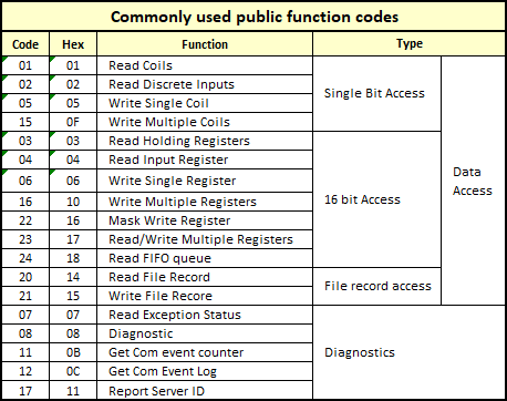
among which, The function codes that support broadcast mode include:
- 0x05 Write a single coil
- 0x06 Write a single hold register
- 0x0F Write multiple coils
- 0x10 Write multiple hold registers
Except for messages in broadcast mode, All other query messages hope to obtain a normal response message. If everything is normal, The slave device will return a normal response message, The function code of the response message is consistent with the function code of the request message.
Besides, Function codes for word operations, There is a size end issue with multi byte storage, Therefore, the master station equipment and slave station equipment must maintain consistent rules for processing, Promise Modbus Byte order of data fields in transmission.


Leave a Reply