
Complete Analysis of Modbus Function Codes: A Practical Guide from Basic to Advanced 21 Standard Function Codes
Keywords:Modbus Function Code, Modbus 01 02 03 04 05 06 15 16, Modbus Read Register, Modbus Write Coil
The Function Code is the soul of the Modbus protocol. It defines the operation that the master station performs on the slave station - whether it is reading data or writing data, and whether the operation targets coils, discrete inputs, holding registers, or input registers. Understanding the purpose, message format, and applicable scenarios of each function code is the cornerstone of proficiency in Modbus communication.
Based on the Modbus protocol specification V1.1b3, this article systematically analyzes all 21 standard function codes (including common function codes, user-defined function codes, and reserved function codes), accompanied by complete message examples and programming implementations, to help you progress from being a "functional engineer" to a "truly understanding expert".
I. Relationship between Modbus Data Model and Function Codes
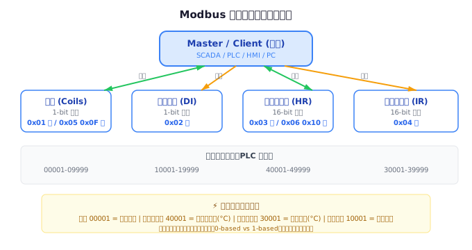
Before delving into the function codes, it is necessary to understand the Modbus data model. Modbus defines four data areas:
| Data Area | Access Type | Size | Address Range | Typical Applications |
|---|---|---|---|---|
| Coils | Read/Write | 1 bit | 00001-09999 | Digital Outputs (DO) |
| Discrete Inputs | Read-Only | 1 bit | 10001-19999 | Digital Inputs (DI) |
| Holding Registers | Read/Write | 16 bit | 40001-49999 | Analog Output/Parameters |
| Input Registers | Read-Only | 16 bit | 30001-39999 | Analog Input (AI) |
Important Note:In actual protocol messages, the "protocol address" starts from 0. For example, the protocol address corresponding to the holding register 40001 is 0x0000. This "offset 1" design is the most confusing part for beginners.
II. Function Code Classification System
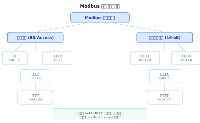
Modbus function codes are divided into three major categories:
- Common function codes (1-64, 73-99, 111-127):Standardized and defined by the Modbus organization to ensure interoperability between devices from different manufacturers
- User-defined function codes (65-72, 100-110):Left to device manufacturers for custom implementation, not universally applicable.
- Reserved function code:Has been used by some companies for traditional products (such as 8-11, 12-15, etc.).
III. In-depth Analysis of Bit Access Function Codes.
3.1 Function Code 0x01 — Read Coils.
Function:Read the ON/OFF status of continuous coils (DO) in the slave station. This is the most basic bit read operation.
Request Message (RTU):
从站地址 | 0x01 | 起始地址高 | 起始地址低 | 数量高 | 数量低 | CRC
示例:读取从站 1 的线圈 0x0013~0x0037(20~56 号线圈,共 37 个)
01 01 00 13 00 25 [CRC]
→ 从站地址=1, 功能码=0x01, 起始地址=0x0013(19), 数量=0x0025(37)
Response Message:
从站地址 | 0x01 | 字节数 | 数据... | CRC
01 01 05 CD 6B B2 0E 1B [CRC]
→ 5 个字节数据, CD=1100 1101 (线圈 27-20 的状态)
Key Constraints:
- Up to 2000 coils can be read at a time (0x07D0)
- Bit packing rule in response: The LSB of the first byte corresponds to the starting address coil
- . If the requested quantity is not a multiple of 8, the high bit of the last byte is padded with 0s
. 3.2 Function code 0x02 — Read Discrete Inputs
Function:Read the status of continuous discrete inputs (DI) in the slave station. The message format is exactly the same as 0x01, but the operation is on the read-only discrete input area.
Difference from 0x01:0x01 reads readable and writable coils (usually corresponding to physical DOs), while 0x02 reads read-only discrete inputs (usually corresponding to physical DIs such as limit switches, sensor status, etc.).
示例:读取从站 1 的离散输入 0x00C4~0x00DB(197~220,共 24 个)
请求: 01 02 00 C4 00 18 [CRC]
响应: 01 02 03 AC DB 35 [CRC]
→ 3 个字节, AC=1010 1100, DB=1101 1011, 35=0011 0101
3.3 Function code 0x05 — Write Single Coil
Function:Set a single coil to ON or OFF. This is the simplest write operation.
Request message:
从站地址 | 0x05 | 线圈地址高 | 线圈地址低 | 输出值高 | 输出值低 | CRC
输出值: 0xFF00 表示 ON, 0x0000 表示 OFF

示例:将从站 1 的线圈 0x00AC(173 号)置为 ON
01 05 00 AC FF 00 [CRC]
Response message:Normal response is completely consistent with the request (echo).
Programming example (Python):
import minimalmodbus
instrument = minimalmodbus.Instrument('/dev/ttyUSB0', 1)
instrument.serial.baudrate = 9600
# 写单个线圈: 地址 0x00AC = ON
instrument.write_bit(0x00AC, 1)
3.4 Function code 0x0F — Write Multiple Coils
Function:Write multiple continuous coils at once. When multiple DOs need to be controlled simultaneously, 0x0F is much more efficient than calling 0x05 multiple times.
请求报文格式:
从站地址 | 0x0F | 起始地址高 | 起始地址低 | 数量高 | 数量低 | 字节数 | 数据... | CRC

示例:将从站 1 的线圈 0x0013~0x001C(20~29,共 10 个线圈)分别置为:
20: ON, 21: OFF, 22: ON, 23: ON, 24: OFF, 25: ON, 26: ON, 27: OFF, 28: ON, 29: OFF
二进制: 01 0110 1101 → 高位补0 → 0xCD01... 等等这里需要仔细计算
实际报文: 01 0F 00 13 00 0A 02 CD 01 [CRC]
IV. In-depth Analysis of Register Operation Function Codes (16-bit Access)
4.1 Function code 0x03 — Read Holding Registers
Function:Read the values of continuous holding registers. This is the most frequently used function code in Modbus, without a doubt. Almost all data acquisition scenarios use 0x03.
请求报文格式:
从站地址 | 0x03 | 起始地址高 | 起始地址低 | 寄存器数量高 | 寄存器数量低 | CRC

示例:读取从站 1 的保持寄存器 0x006B~0x006D(108~110,共 3 个寄存器)
请求: 01 03 00 6B 00 03 [CRC]
响应: 01 03 06 02 2B 00 00 00 64 [CRC]
→ 6 个字节 = 3 个寄存器 × 2
→ 寄存器 108: 0x022B = 555
→ 寄存器 109: 0x0000 = 0
→ 寄存器 110: 0x0064 = 100
Key constraints:
- Read up to 125 registers at a time (0x007D)
- If reading 32-bit data (float32/int32), ensure that the number of registers is even
- Byte Order Issue: Different devices may use big-endian or little-endian to store multi-byte data.
4.2 Function Code 0x04 — Read Input Registers
Function:Read the values of consecutive input registers. The message format is exactly the same as 0x03, but it operates on read-only input register areas (such as ADC sampling values, sensor raw values, etc.).
示例:读取从站 1 的输入寄存器 0x0008(地址 9,AI 通道 1)
请求: 01 04 00 08 00 01 [CRC]
响应: 01 04 02 00 0A [CRC]
→ 输入寄存器 9 的值 = 0x000A = 10
4.3 Function Code 0x06 — Write Single Register
Function:Write a 16-bit value to a single holding register.
请求报文格式:
从站地址 | 0x06 | 寄存器地址高 | 寄存器地址低 | 写入值高 | 写入值低 | CRC

示例:将从站 1 的保持寄存器 0x0001 写入值 0x0003
请求: 01 06 00 01 00 03 [CRC]
响应: 01 06 00 01 00 03 [CRC](回显)
Programming Example (C#):
// 使用 NModbus4 库
using Modbus.Device;
using System.IO.Ports;

var port = new SerialPort("COM3", 9600, Parity.None, 8, StopBits.One);
port.Open();
var master = ModbusSerialMaster.CreateRtu(port);
master.WriteSingleRegister(1, 0x0001, 3); // 从站1, 地址1, 值3
4.4 Function Code 0x10 — Write Multiple Registers
Function:Write multiple consecutive holding registers at once. This is an efficient tool for batch configuration parameters.
请求报文格式:
从站地址 | 0x10 | 起始地址高 | 起始地址低 | 寄存器数量高 | 寄存器数量低 | 字节数 | 数据... | CRC

示例:向从站 1 的寄存器 0x0001 和 0x0002 分别写入 0x000A 和 0x0102
请求: 01 10 00 01 00 02 04 00 0A 01 02 [CRC]
→ 字节数=4(2个寄存器×2)
响应: 01 10 00 01 00 02 [CRC]
→ 响应仅返回起始地址和寄存器数量
Key Constraints:
- Up to 123 registers can be written at a time (0x007B)
- The number of bytes must be equal to "the number of registers × 2"
- Writing failure may lead to confusion in the slave parameters, and it is recommended to back up first
V. Detailed Explanation of Advanced Function Codes
5.1 Function Code 0x07 - Read Exception Status
Function:Quickly read the 8 exception status bits of the slave. This is a simple yet powerful diagnostic function code, with a request message consisting of only 2 bytes (address + function code) and a response of only 3 bytes.
请求: 01 07 [CRC]
响应: 01 07 6D [CRC]
→ 状态字节 0x6D = 0110 1101,各厂商定义各 bit 含义
5.2 Function Code 0x08 - Diagnostics
Function:Used for communication link diagnosis, with a total of 16 sub-function codes. The most common use is "loop test" (sub-function code 0x0000), which is used to detect whether the slave is online and able to process messages normally.
| Sub-function Code | Name | Purpose |
|---|---|---|
| 0x0000 | Loop test | Echo request data, verify communication link |
| 0x000A | Clear counter | Reset communication event counter |
| 0x000B | Read bus message count | Read the total number of bus messages detected by the slave station |
| 0x000C | Read communication error count | Read CRC check error count |
| 0x000D | Read exception error count | Read the number of exception responses returned by the slave |
| 0x000E | Read slave message count | Read the number of messages processed by the slave |
| 0x000F | Read slave no response count | Read the number of messages that do not require a response due to broadcasting |
回路测试示例:
请求: 01 08 00 00 12 34 [CRC]  → 子功能码=0x0000, 数据=0x1234
响应: 01 08 00 00 12 34 [CRC]  → 必须完全回显请求数据
5.3 Function code 0x0B — Read communication event counter
Return the communication event counter and status word of the slave for monitoring communication quality.
5.4 Function Code 0x16 — Mask Write Register
Function:Performs bit operations on a single register using an AND mask and an OR mask. This is one of the most ingenious function codes in Modbus — it allows for atomic modification of specific bits in a register without reading the current value.
请求报文格式:
从站地址 | 0x16 | 地址高 | 地址低 | AND掩码高 | AND掩码低 | OR掩码高 | OR掩码低 | CRC

操作逻辑: Result = (Current_Value AND And_Mask) OR (Or_Mask AND (NOT And_Mask))

示例:将寄存器 0x0004 的 bit 0~3 清零,同时设置 bit 4~7 = 0b1010
AND掩码 = 0xFFF0(清除低4位), OR掩码 = 0x00A0(设置 bit5 和 bit7)
请求: 01 16 00 04 FF F0 00 A0 [CRC]
VI. Quick Reference Table for Function Codes
| Function Code | Name | Operating Object | Operation Type | Maximum Quantity | Frequency of Use |
|---|---|---|---|---|---|
| 0x01 | Read Coils | Coil | Read | 2000 | ★★★★☆ |
| 0x02 | Read Discrete Inputs | Discrete Input | Read | 2000 | ★★★☆☆ |
| 0x03 | Read Holding Registers | Hold Register | Read | 125 | ★★★★★ |
| 0x04 | Read Input Registers | Input Register | Read | 125 | ★★★★☆ |
| 0x05 | Write Single Coil | Coil | Write | 1 | ★★★☆☆ |
| 0x06 | Write Single Register | Hold register | Write | 1 | ★★★★★ |
| 0x0F | Write Multiple Coils | Coil | Write | 1968 | ★★★☆☆ |
| 0x10 | Write Multiple Registers | Hold register | Write | 123 | ★★★★★ |
| 0x16 | Mask Write Register | Hold register | Read/Write | 1 | ★★☆☆☆ |
| 0x17 | Read/Write Multiple Regs | Hold Register | Read/Write | 125/121 | ★★☆☆☆ |
VII. Function Code Selection Decision Tree
In actual development, selecting the appropriate function code is a crucial decision. The following is the selection decision process:
- Need to read the digital output status?→ 0x01 (coil) / 0x02 (discrete input)
- Need to read analog values or parameters?→ 0x03 (hold register) / 0x04 (input register)
- Need to set a single digital output?→ 0x05
- Need to set a single parameter?→ 0x06
- Need to set parameters in bulk?→ 0x10
- Need to set digital outputs in bulk?→ 0x0F
- Need to modify certain bits of a parameter without affecting other bits?→ 0x16
- Need to perform simultaneous read and write operations (such as atomic operations to read old parameters and write new ones)?→ 0x17
VIII. Common Pitfalls and Best Practices
8.1 Byte Order Pitfall
The Modbus protocol specifies that 16-bit registers use Big-Endian byte order, but the byte order for 32-bit data (such as float32) is not specified at the protocol level. There are commonly four arrangements:
| Arrangement | Register 1 | Register 2 | Common Manufacturers |
|---|---|---|---|
| ABCD (Big-Endian) | High 16 Bits | Low 16 Bits | Schneider, ABB |
| CDAB (Little-Endian) | Low 16 Bits | High 16 Bits | Siemens S7-200 |
| BADC (Word-Swap Big) | Byte Swap | - | Some Domestic Brands |
| DCBA (Word-Swap Little) | Completely Reversed | - | A Few Special Devices |
8.2 Broadcast Address (Address 0)
In RTU mode, using slave address 0 indicates broadcast - all slaves execute the command but do not return a response. Only write operation function codes (0x05, 0x06, 0x0F, 0x10) support broadcast.
8.3 Don't Request Too Much at Once
Although the specification allows for the simultaneous reading of 125 registers with 0x03, it is not recommended to read too many at once. Reasons:
- Increased communication delay (at a baud rate of 9600, 125 registers require approximately 270ms)
- Increased probability of CRC check errors
- Memory limitations of some slaves may lead to buffer overflows
Recommendation:Limit the number of registers read at once to 20 to 50, and read them in multiple small batches.
IX. Practical Case: Building a Modbus Data Acquisition System
The following is a typical Modbus data acquisition process, demonstrating how to combine different function codes:
// C 语言伪代码 - 典型 Modbus 采集流程
void modbus_acquisition_task(void) {
// 步骤 1: 读取设备状态(离散输入)
uint8_t di_data[2];
modbus_read_inputs(0x02, &di_data, 16); // 读16个DI
// 步骤 2: 读取模拟量(输入寄存器)
uint16_t ai_data[8];
modbus_read_input_regs(0x00, &ai_data, 8); // 读8个AI通道
// 步骤 3: 读取运行参数(保持寄存器)
uint16_t params[20];
modbus_read_holding_regs(0x00, ¶ms, 20);
// 步骤 4: 根据业务逻辑写入控制命令
if (need_start_motor) {
modbus_write_coil(0x0005, 1); // 启动电机
}
// 步骤 5: 如果需要修改参数
if (need_set_temp) {
modbus_write_register(0x0010, 250); // 设定温度 25.0°C
}
}X. Summary
Function codes are the "verbs" of the Modbus protocol - they define what operations the master station performs on the slave station. Mastering the message format and applicable scenarios of function codes is equivalent to mastering the core syntax of Modbus communication. It is recommended to use the quick reference table and decision tree of function codes in this article as a reference manual for daily development, and gradually deepen your understanding during actual debugging.
In the next article, we will delve into the differences between Modbus RTU and Modbus TCP transmission modes, providing a comprehensive analysis of their applicable scenarios and performance characteristics from the physical layer to the application layer.
Related Reading:Complete Manual for Modbus Exception Response Codes and Troubleshooting | In-depth Comparison between Modbus RTU and TCP | Modbus CRC Checking Principle and Programming Implementation


Leave a Reply