
Overview
In automation and control systems, the Modbus TCP protocol is widely used for communication between PLCs. This article will explore how to implement Modbus TCP communication between two S7-1200 PLCs, with a focus on client programming and the communication process.
Experimental Environment Setup
- Operating System: WIN7 SP1 Professional Edition 64-bit
- Programming Software: STEP 7 Professional V13 SP1 Update 5
- System Hardware: CPU1212C 6ES7212-1AE40-0XB0 V4.1 and CPU1215C 6ES7215-1AG40-0XB0 V4.1
Basic Configuration for Modbus TCP Communication
- Client: CPU 1212C
- Server: CPU 1215C
- IP Address: Client 192.168.0.6, Server 192.168.0.4
- Port Number: Client 0, Server 502
- Hardware Identifier: 64
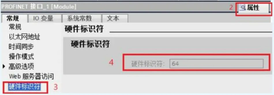
The hardware identifier can be found in the "Device Configuration" section. Double-click the PROFINET interface, and then view the "Hardware Identifier" in the "Properties".
Programming and Communication Process of S7-1200 as a Client
- The S7-1200 client side needs to call the MB CLIENT instruction block.
- This instruction block mainly completes the tasks of establishing TCP connections between the client and server, sending command messages, receiving responses, and controlling server disconnection.
Call MB_CLIENT
to invoke the MB_CLIENT instruction block within the program segment of block >OB1. Upon invocation, a background DB will be automatically generated. Simply click "OK"
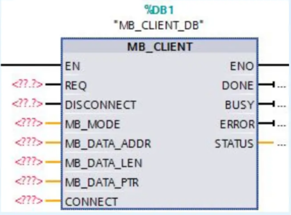
. MB_CLIENT pin definitions:
- REQ: Communication request with the server, active on the rising edge.
- DISCONNECT: This parameter allows for the control of establishing and terminating connections with the ModbusTCP server. 0: Establish connection; 1: Disconnect.
- MB MODE: Selects the Modbus request mode (read, write, or diagnostic).
- MB_DATA_ADDR: Starting address of the data accessed by the "MB_CLIENT" instruction.
- MB DATA LEN: Data length: The number of bits or words accessed by the data.
- MB_DATA_PTR: Pointer to the Modbus data register.
- CONNECT: Pointer to the connection description structure. Uses the TCON_IP_v4 data type.
- DONE: Once the last job is successfully completed, immediately set the output parameter DONE to "1".
- BUSY: Job status bit: 0: No "MB_CLIENT" job is being processed; 1: "MB_CLIENT" job is being processed.
- ERROR: Error bit: 0: No error: 1: An error occurred. Please check STATUS for the cause of the error.
- STATUS: Detailed status information of the instruction.
Pointer type of CONNECT pin
Create TCON_IP_v4 structure:
- Aglobal data block DB2needs to be created, and the TCON IP v4 data structure should be defined within it for storing communication configuration.
- Double-click to open DB2, define the variable name as "aa", and set the data type as "TCON IP v4" (you can copy TCON IP V4 into the dialog box);
- Click the "Enter" button to complete the creation of this data type structure
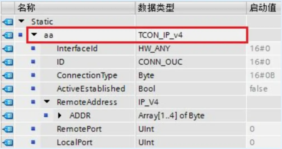
The pin definition of the TCON IP v4 data structure is as follows:
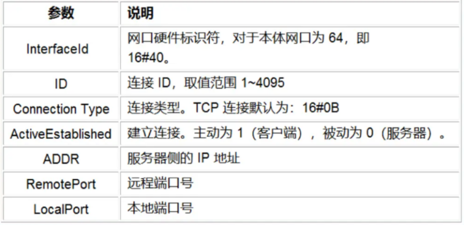
Note:
- The CONNECT pin needs to be filled in withThe method of symbol addressingis
- TCON_IP_v4, which is a system data type, not created in the PLC data type.
- LocalPort generally uses thedefault value 0, meaning that a random port is used locally.
Create an MB_DATA_PTR data buffer
1. Create a global data block DB3, and refer to Figure 2 for the creation method. Together with the DB2 created in the previous step, they are located in the CPU program block;
The names of the two generated DB blocks are:

2. Establish a data type of Word array to store data during communication; MB_DATA_PTR data buffer structure:
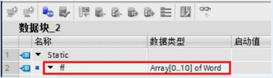
Note that
- the specified data buffer can be in a DB block or M memory area address;
- The DB block can be an optimized data block or a standard data block structure;
- if it is an optimized data block structure, it must be a basic data type array;
- if it is a standard data block structure, the pin is filled in using a pointer;
- the data buffer specified by MB_DATA_PTR must be large enough, at least reaching MB_DATA_LEN bits (when accessing input bits and output bits) or words (when accessing hold registers and input words);
- this article uses a standard data block (default) as an example for programming.
Modify the DB block attribute to a standard block structure:
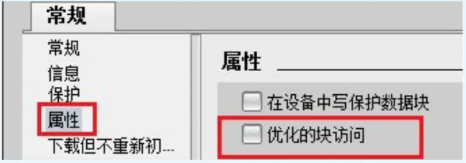
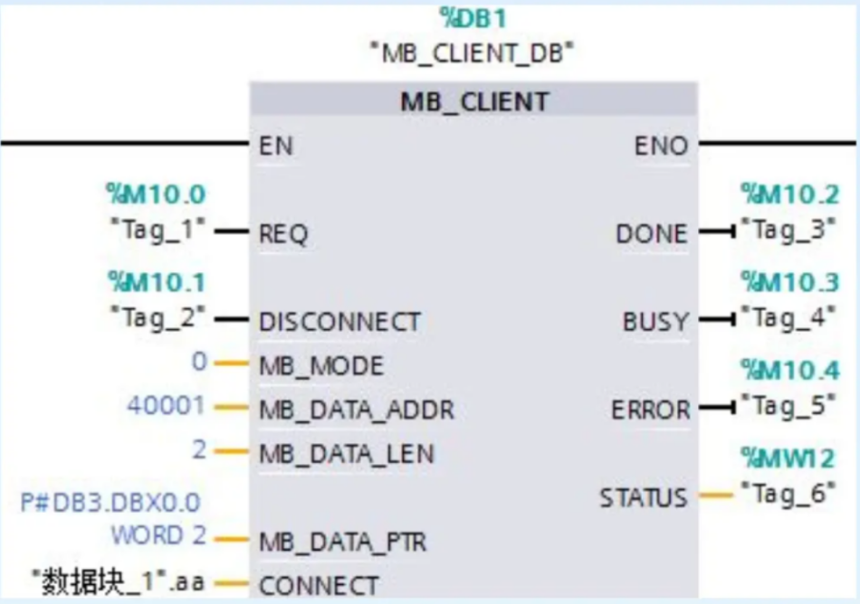
the client side completes the instruction block programming
calls the MB_CLIENT instruction block, using function code 03 to read the values of 2 hold registers from the server, with MB_MODE = 0, MB_DATA_ADDR = 40001, and MB_DATA_LEN = 2
Note:
- for this example, the partner is another S7-1200, but in reality, it can be any device that supports Modbus TCP server, as long as the appropriate values are set in the parameter pins and the correct communication parameters are set in CONNECT.
- If the S7-1200 acts as a Modbus TCP client and needs to connect to multiple Modbus TCP servers simultaneously, multiple MB_CLIENTs need to be used;
- if there are multiple communication jobs in a Modbus TCP connection, and each job calls MB_CLIENT once, the same background data block must be used for each call, and CONNECT also uses the same parameters
Download and Test
After completing the programming, download the entire project to the S7-1200 PLC. Once the server side is ready, initiate communication by triggering the rising edge of the REQ pin of the MB CLIENT instruction block. The read data will be stored in the DB block variable specified by the MBDATA PTR pin.
Conclusion
Through the above steps, Modbus TCP communication between two S7-1200 PLCs can be successfully achieved. Client programming involves detailed instruction block configuration and data structure definition, which is crucial for achieving efficient and reliable communication. This communication method is widely used in industrial automation, providing a stable platform for data exchange between devices.


Leave a Reply