
One, Equipment Overview
The radar wave online flow measurement system is a fully automatic flow online monitoring system that uses radar current meters as sensors, installs one or more radar wave current meters on the section according to the requirements of the vertical line layout for speed measurement, and automatically completes functions such as vertical line velocity measurement, section flow calculation, data analysis, and report output under the control of the control unit.
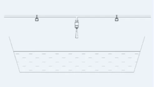
System Installation Diagram
2, System composition
- Radar Wave Velocimeter
This system uses Doppler radar sensors to measure surface flow velocities of rivers, mud, sewage, etc. It has the advantages of high measurement accuracy, small size, light weight, low power consumption, no corrosion from sewage, no influence from sediment, and ensures personnel safety. In addition, this system can also be connected to float type digital meters, bubble type water level meters, and radar water level meters to provide water level data for flow calculation.
- water level gauge
In addition, this system can also be connected to float type digital meters, bubble type water level meters, and radar water level meters to provide water level data for flow calculation.
- The control unit
includes a system controller, GPRS (4G) communication module, flow calculation unit, etc. Its main functions are to complete communication with platform software, control the operation of radar wave current meter, collect water level data, perform flow calculation, and store and send flow data.
- The power supply unit
includes solar panels (mains power), solar controllers (switch power supply), batteries, etc., which provide power for the operation of the system.
- Cableway (support)
includes support columns (cableway), lightning protection grounding, etc.
- Platform software
includes user permission management module, site management module, flow measurement calculation module, data reporting module, etc. Mainly responsible for site management, flow measurement data processing, and related statistical analysis functions.
- Equipment Installation
1. Installation Site Selection
(1) Point Selection Principle
A. Relatively concentrated water flow, no backflow, no turbulence, etc;
B. Good hydrological conditions with certain representativeness and the ability to avoid the influence of floating debris;
C. There are no tall buildings around to ensure smooth signal flow;
D. The instruments and supporting equipment are relatively high off the ground, which improves the safety factor of the system;
E. The probe installation is firm and stable;
F. Strive for beautiful and elegant construction, with reliable quality;
(2) Section selection
Choose a straight section of the river, avoiding bends or intersections as much as possible. The length of the straight section should ideally be three times the width of the river.
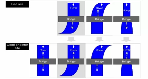
(3) Selection of installation location
The location of the measuring point is representative, and it is best to choose the center position; Avoid plants that sway with the wind and protrude from the water surface.
2. Installation angle
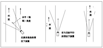
The vertical angle of the instrument is 55-60 degrees, and when installed horizontally, the horizontal angle is ± 1 degree.
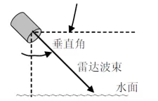
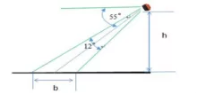
The cosine effect causes the displayed speed of radar equipment to be lower than the actual surface velocity. This effect occurs when the target path (water flow direction) is not parallel to the radar antenna.
3. Installation method
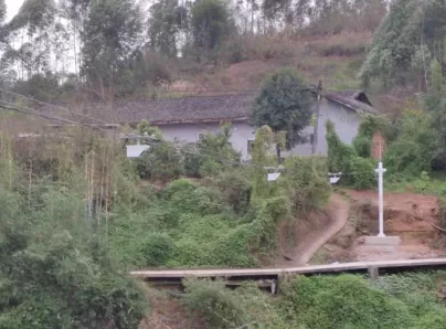
Radar current meters can be fixedly installed on the foundation of riverbanks or canal walls, or on the side walls of bridge piers or other buildings. As long as the location is chosen appropriately, the installation is firm, and the debugging is timely, satisfactory results can generally be achieved. In the long-term project practice process, according to the actual situation of different installation sections and local conditions, the main installation methods include the following:
| Installation method | Scope of Application | characteristics |
| Cantilever | A mountain stream river with a station with a self recording platform or a small station house on the bank | Easy installation; Fast and secure measurement, real-time and accurate data; Small maintenance volume; Strong anti-interference ability |
| Bridge type | Stations with bridges near the daily test section | |
| Set up a gantry bridge structure | The river section is narrow and there are no fixed installation points nearby |
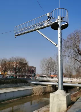
1) Cantilevered structure
Using a cantilever bracket to extend the equipment out of the water surface, measure the water surface velocity at a designated point on the cross-section, convert the water surface velocity coefficient to the vertical average velocity, and then calculate the water area based on the measured water level and borrowed cross-section data to achieve flow measurement.
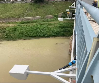
2) Fixed to the existing bridge structure
Installed on bridges according to local conditions, due to the obstruction of bridge piers, there may be uneven distribution of river flow field, usually requiring the installation of multiple sets of equipment for calculating the average flow velocity.
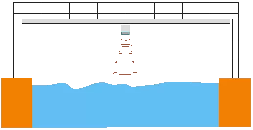
3) Set up a gantry bridge structure
In some sections where there is no fixed installation pivot or representative flow measurement points are complex, manually setting up a gantry bridge can flexibly solve the installation problem of fixed radar current meters at such stations. The gantry bridge is helpful for later system operation and maintenance.
4) Cableway Installation
In some sections without fixed installation supports or representative flow measurement points with complex cross-sections, and with large river spans, it is not possible to install them in the form of gantry frames. Cableway installation can flexibly solve the problem of installing fixed radar current meters at such stations. By moving the probe to the designated position with a hand cranked winch, flow measurement work can be carried out.
4. Bracket Design andAnti theft Measures
Customize brackets suitable for installation based on site conditions.
General bracket design (sub control box and pole bracket):
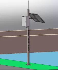
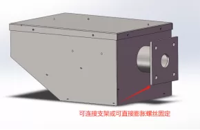
The overallbracket is made of stainless steel material, and the surface of the pole bracket is sprayed with plastic and words such as "Legal protection of flood prevention facilities strictly prohibited from destruction" (the spray color is determined by oneself, the font is large black font, with a height of 80), and the solar energy orientation is due south; The material of the sub control box is stainless steel, with a spray coating on the surface (color to be determined). To prevent personnel from damaging the sub control box, an additional extension bracket needs to be processed, with an extension length of not less than 1.2m (a distance that personnel cannot easily touch or directly damage). The bottom is fixed with expansion screws, which are made of M8-M10 stainless steel expansion screws. If there is a ball machine on site, it can be connected to the system and the equipment situation can be checked at any time to prevent malicious damage and theft of equipment.
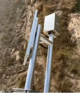
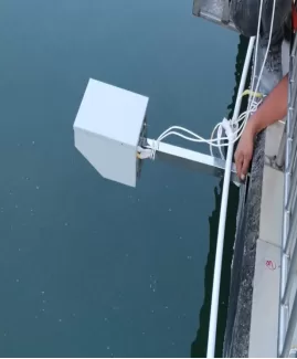
Stainless steel bracket installation
Installation of Radar
After the radar bracket is processed, it is fixed with expansion screws. The radar flowmeter is installed on the bracket at an angle between 55 ° -60 °. The wiring should be neat, and solder wires should be used to weld the wiring connections. Galvanized wires (in accordance with national standards) should be used, and wire conduits should be used outside the connected wires (the number and location of wiring should be determined according to the cross-sectional situation).
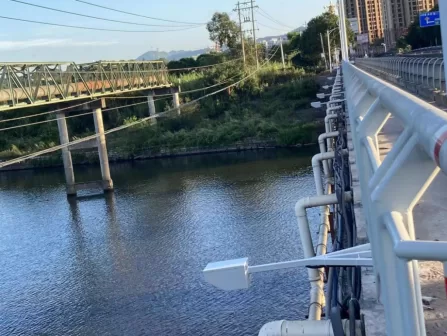
On site Installation Diagram
four, Equipment Installation and Debugging
Power Supply System Connection
1. The solar panel is connected using a two core power cord. Thread the power cord out of the wiring hole of the installation tube, open the black plastic box under the solar panel, there are two terminal posts inside, and the right terminal post is connected to the red cable of the+pole and dual core wire; The terminal on the left is connected to a white cable with one pole and two core wires. When wiring, strip the two core cables by 20mm, fold them in half, and twist them into strands. Insert them into the two wiring holes of commonly used signaling components in the wiring socket, tighten them with screws, and finally fix the black plastic sealing box with screws and seal it with sealant.
2. Fix the solar panel bracket onto the solar panel using M6 bolts.
3. Fix the solar panel with connected wires and fixed brackets on the upright pole (if the solar panel is installed in the station building, use screws to fix it)
4. Fix the charging controller on the installation base plate, and connect the solar cell, battery, and electrical appliance (RTU) to the corresponding wiring terminals according to the instructions, tighten the screws to avoid poor contact. 5. Connect the battery to the charging controller, with the red wire connected to the positive pole and the black wire connected to the negative pole. After the connection is fixed, place the battery in the equipment box.
5. Connect the battery to the charging controller, with the red wire connected to the positive pole and the black wire connected to the negative pole. After fixing the connection, place the battery into the equipment box.
RTU equipment box line connection
1. Install the entire equipment box at the selected location in the station building (or outdoor pole installation).
2. Connect the RTU power cable to the output terminal of the solar controller.
3. After checking and confirming that all types of cables are connected correctly, turn on the power switch of the equipment box and power up the equipment.
4. After the equipment is powered on and self checks normally, set the operating parameters of the RTU according to the requirements. After the parameter settings are completed, the testing work can be carried out.
After the parameter settings are completed, the testing work can be carried out.
Connection and Wiring of Water Level Gauge
1. According to the type of water level gauge used on the station, it is necessary to connect the water level gauge RTU and lead it out during debugging (the same as installing a self installed water level gauge).
2. The wiring method adopts the parallel wiring method and is covered with PVC conduit. After the wiring is completed, the road surface is patched with concrete.
3. Connect the water level gauge line to the terminal block at the RTU collection point of the device.
4. Water level data acquisition test. Under normal circumstances, the RTU sends water level messages to the municipal water level platform every 5 minutes through a mobile GPRS channel. The flow measurement parameters can be set in the RTU. According to the hydrological data collection criteria, we preset 12 sets of flow information collection for the whole day (automatic measurement every two hours) for additional measurement. After additional testing, the data will be sent to the municipal water platform receiving software and local database through a mobile GPRS channel within 1 minute. The local data will then receive and process the data, and the database will forward the processed data to the server query and warning database. The received flow data information will be analyzed through database analysis software, and finally displayed on the platform.
Upload data to the municipal water situation platform
Under normal circumstances, the RTU sends water level messages to the municipal water level platform every 5 minutes through the mobile GPRS channel. The additional measurement parameters for flow can be set within the RTU. According to the hydrological data collection criteria, we preset that 12 sets of flow information collection can be set throughout the day (with automatic additional measurement every two hours) for additional measurement. After additional testing, the data will be sent to the municipal water platform receiving software and local database through a mobile GPRS channel within 1 minute. The local data will then receive and process the data, and the database will forward the processed data to the server query and warning database. The received flow data information will be analyzed through database analysis software, and finally displayed on the platform.
Method for uploading data to the Municipal Water Information Platform
sends 5-minute water level, flow rate, and flow velocity data to the designated server database of the municipal water level platform through a mobile GPRS channel; At present, mobile GPRS can be used for multi platform transmission (with a distribution of 5).
Distribution Platform Steps:
1. The owner is required to provide the IP address and data receiving port number of the designated server on the municipal water situation platform;
2. On site, set the designated server IP and device port number for the city water level platform on the mobile GPRS channel for data reception;
3. A new database needs to be created on the designated server of the municipal water situation platform to facilitate data reception (if it has already been created, the username and password of the server database need to be provided for data access)
4. After creating the database, a software platform needs to be built on the designated server to facilitate owners to view the corresponding water situation data in a timely manner.
5. Set the corresponding device station number on the built platform and observe the data upload situation.
6. Verify the data upload status.
System Testing
mainly tests remote control of equipment (note: before clicking the remote control button, if the parameters of the site equipment are not configured correctly, the site details information cannot be displayed correctly. At this time, parameter configuration needs to be carried out first. For specific operations, please refer to the operation instructions of the subsequent parameter configuration module). Click on "Add Test" to see if the equipment is collecting data normally.
System acceptance
Functional acceptance. Confirm that the fixed radar flow measurement system meets all the technical performance requirements of the equipment in this project.
Performance acceptance. Evaluate the performance of the fixed radar flow measurement system, including measurement accuracy, stability, and reliability.
FixedRadar Flow Measurement SystemTraining Outline
| Course Theme | Course Outline | Teaching Hours (Hours) |
| Fixed Radar Flow Measurement System | (1) Basic Knowledge of Fixed Radar Flow Measurement System: Introduce the characteristics, principles, application scenarios, etc. of the equipment. | 1.5 |
| (2) Flow measurement method for fixed radar flow measurement system. Basic parameter settings, data import and export recalculation, etc. | 2 | |
| (3) Basic operations of the fixed radar flow measurement system on site, how to measure flow on site, how to view data on mobile devices, etc. | 2 | |
| (4) Basic functions of the entire system of the fixed radar flow measurement system, abnormal data processing, etc. | 2 | |
| (5) System maintenance and upkeep: Introduce how to properly maintain and upkeep the fixed radar flow measurement system, including regular inspections, dust cleaning, component replacement, etc. | 4 | |
| (6) Practical Operation Case Analysis: Through practical operation cases, analyze the application scenarios, precautions, data accuracy, etc. of fixed radar flow measurement systems to improve students' practical operation ability and the ability to diagnose, eliminate, and solve common faults. | 3 | |
| (7) Course Summary and Q&A: Summarize the course content, answer students' questions, and provide corresponding operational guidance and suggestions. | 2 |
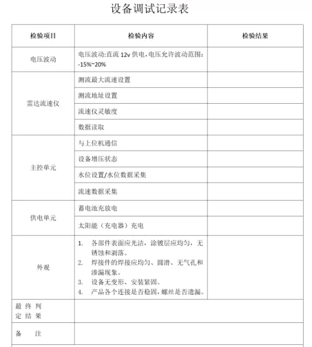


Leave a Reply