
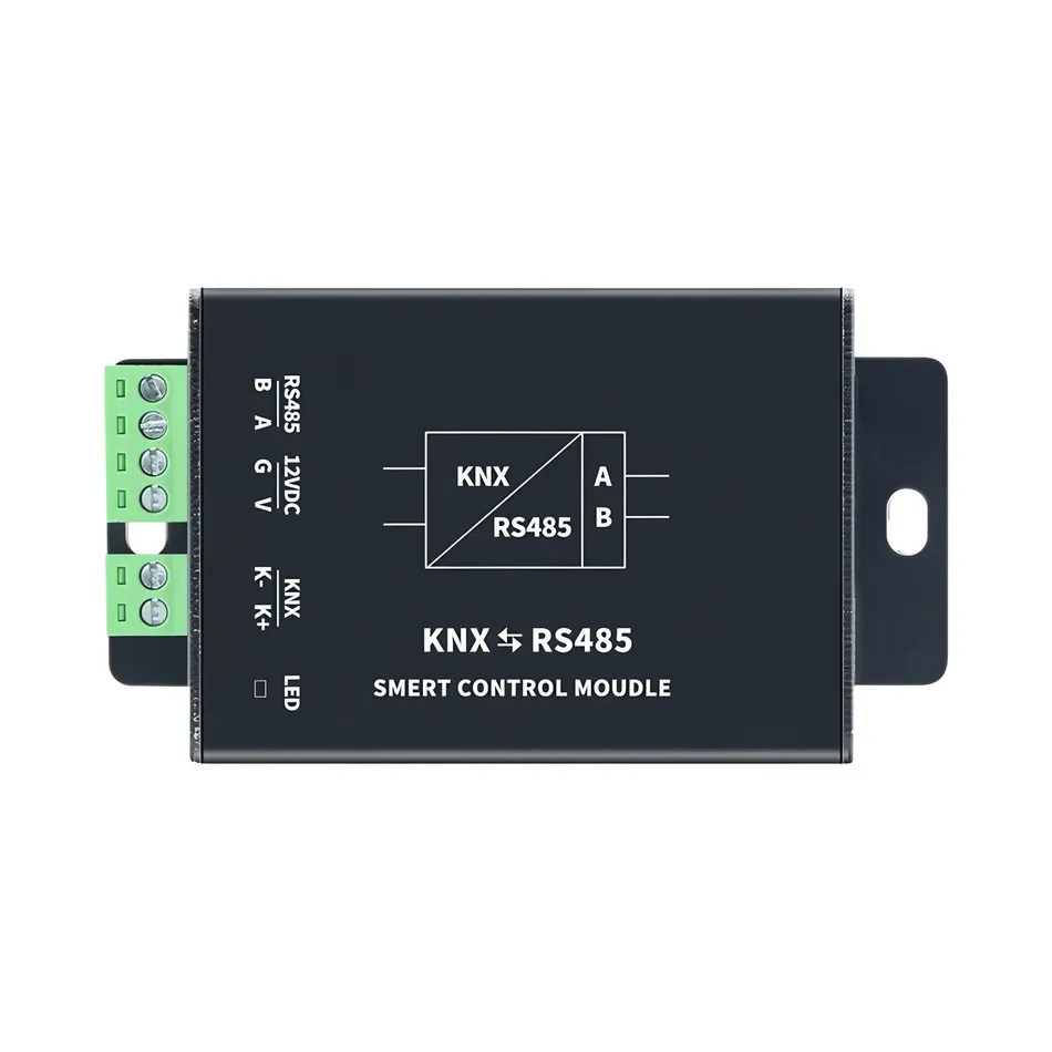
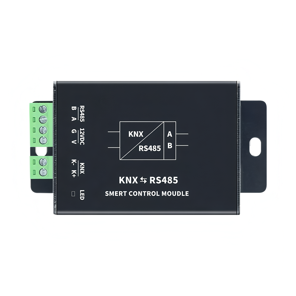
I. Product Overview
This module is a bidirectional protocol conversion device designed specifically for intelligent building systems, which enables data transmission between KNX bus and RS-485 bus. Protected by industrial grade aluminum alloy casing, supporting dual power supply and intelligent error isolation, suitable for building automation system integration.
Product purchase:https://www.modbus.cn/product/30795.html
II. Core Function
- Bidirectional Transparent Transmission
- KNX Data Real time Forwarding to 485 Bus
- 485 Data After Protocol Verification, Forwarding to KNX Network
- Intelligent Protection
- KNX Dedicated Chip Isolation Non standard Protocol
- Automatic Discarding of Illegal 485 Data
- Flexible Configuration
- Baud rate supports 1200-112200 adjustable
- Supports custom data mapping rules
- Industrial design
- Dual power independent power supply design (KNX/12V DC)
- Aluminum alloy shell, 8 × 4.5 × 1.8cm compact size
III. Technical parameters
| Project | Specification |
|---|---|
| Operating voltage | KNX bus power supply+12V DC |
| Standby current | ≤ 10mA |
| Communication Interface | KNX terminal/RS-485 wiring terminal |
| Baud rate range | 1200-115200bps |
| Operating Temperature | -20℃~+60℃ |
| Protection Rating | IP20 |
| warranty period | 1 year |
4, Installation Guide
Wiring Instructions
KNX侧:
  红色 - KNX+
  黑色 - KNX-

485侧:
  A - 485+
  B - 485-
  12V - 外接电源正极
  GND - 电源负极
Power on process
- Priority connection to KNX bus
- Connect 12V DC power supply
- Observe the status indicator light:
5, Configuration Tutorial
Configure software
Basic Configuration
地址修改协议帧示例(RS485端发送)
默认地址背面有标签标注,或者在RS485通讯下,12V供电先断开后重新上电,设备会反馈它的当前地址.

原地址 + F8 E7 D6 + 新地址  # 5字节地址长度
例如:1A 23 24 25 26 F8 E7 D6 1A 11 11 11 11 (把地址1A 23 24 25 26修改成1A 11 11 11 11)

透传功能控制
开启:地址 + F7 36 49 01 0F
关闭:地址 + F7 36 49 00 0F
Data Mapping Configuration
- Connect to PC using USB to 485 adapter
- Run the configuration software and select the corresponding COM port
- Enter the module address and enter configuration mode
- Click the 'Learn' button to trigger the KNX device
- Edit Conversion Rules in Data Window
- Download Configuration and Exit Configuration Mode
Note: When there is no response during the first learning, you need to first execute the Download Empty Command
Video Tutorial
VI. Precautions
⚠️Important Warning
- Non standard power supply is strictly prohibited from being connected to the KNX side
- 485 bus. It is recommended to increase the terminal resistance
. 7. Troubleshooting
| Phenomenon | Solution |
|---|---|
| indicator light not on | Check power polarity/voltage |
| KNX data not forwarded | Verify if transparent transmission function is enabled |
| 485 data cannot be uploaded | Check baud rate consistency |
| Configuration learning no response | Confirm KNX device group address matching |


Leave a Reply