I. Product Overview
1.1 Introduction
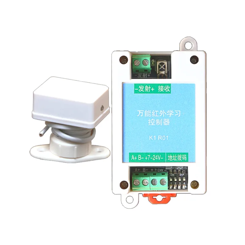
KIR01 controller is a versatile infrared remote control learning controller that supports learning of ordinary NEC encoded infrared remote controls as well as long code encoding for air conditioning. Afterwards, according to the instructions, resend the learned key codes to achieve remote control replication or integration into smart devices. It has multiple control methods, including serial port encoding or 485+MODBUS, and with the provided upper computer software, it can easily achieve product development, greatly reducing the difficulty of developing new products.
Instruction Manual Download
1.2 Basic Parameters
- power supply methodDC 7-24V 100mA (static current<10mA, emission current 600mA)
- Remote control distanceUnidirectional launch head 8 meters away, 4-way launch head radius 6 meters. In addition, a longer range launch head can be optionally selected, with a maximum distance of 20 meters
- communication method: 485 communication, MODBUS protocol+short code communication protocol, 8-bit data, 1-bit stop bit, no parity check bit
- Control mode: 485 MODBUS control, computer side control, on-board extended TTL serial port control
- Baud rate: 2400, 4800, 9600 (factory default), 19200, 115200
- Encoding mode: Supports NEC, air conditioning code, RC-5, RC-6, PWM, PPM, etc.
- Carrier frequency: 38KHz
- Number of key valuesCan learn and store 48 key values
1.3 Interface Description
- 485 interfaceInterface for 485 communication control, 2-wire. When wiring, pay attention to the wire sequence. Connect A to A and B to B. Incorrect wire sequence can cause communication failure.
- Power interfaceAn interface used to supply power to devices, with 2 pins, can be used without distinguishing between positive and negative poles, DC or AC, with a 7-24V power supply (maximum input voltage should not exceed 26V) and a current of not less than 400mA.
- Address dialing codeThe communication address used in MODBUS communication control is the dialing address plus the software setting address. The default software setting address is 1.
- Infrared ReceiverWhen learning the remote control, it is necessary to aim the remote control at the receiving head, press the remote control at a distance of 1 meter, and learn the remote control buttons.
- Work Indicator LightWhen the controller is powered on, it flashes briefly. When learning the remote control, it stays on and goes off when learning is successful. When emitting infrared signals, it flashes briefly.
- Transmitter Interface: Attention should be paid to the positive and negative poles of the wiring. Incorrect wiring sequence can cause the inability to transmit infrared signals. If connecting the transmitter, connect the red wire to+and the black wire to -; If connecting the transmitter, connect the long pin to+and the short pin to -. Infrared light signals cannot be seen by the human eye, but mobile phone cameras can see weak purple light, so sometimes it is necessary to confirm whether the emitter can emit infrared signals, which can be observed using a mobile phone camera.
1.4 Product Application Scenarios
- Smart Home ProductsSuch as multifunctional remote control Rubik's Cube, universal remote control, etc. For this application scenario, it is recommended to use a microcontroller and controller, and adopt a serial port short code communication protocol.
- Industrial control productsSuch as air conditioning controllers, temperature and humidity machine controllers, and constant temperature and humidity controllers.
- Universal Remote Control: For example, combining multiple devices into one remote control.
- Industrial control management: such as archive management room, remote ERP control equipment; Unified management of air conditioning in school dormitories.
1.5 Controller Function Brief Explanation
- Connection to Host Computer: By connecting to the host computer software through a serial port, parameter configuration, key value learning, key value testing, communication protocol debugging, and export/import of infrared code library can be achieved. Convenient batch configuration of controller operating parameters and import of infrared learning code library data. Both the controller and the upper computer software support two communication protocols.
- Communication Protocol: When controlling devices through a serial port, the serial data type supports two communication protocols, determined by the short-circuit point.
- Short Code Communication Protocol: 55 AA 03 01 03 (transmit key 01) The communication protocol is relatively simple, with check bits, simple and reliable, suitable for microcontroller control.
- MODBUS Protocol: Adopting the standard industrial control MODBUS-RTU protocol, it is convenient to directly apply the product to the industrial field without excessive development.
- Learning Remote Control Key Values: After entering infrared learning, aim the remote control at the infrared receiver head, at a distance of 1 meter, and lightly tap the button that needs to be learned.
- Test remote control key value: After successfully learning the corresponding key value, the corresponding key value can be tested through the upper computer or button. Aim the infrared emitter at the device and then test the emission.
- Test button: There is a button on the controller. Long press the button to enter the learning state of key value 0, and short press the button to emit key value 0 (provided that key value 0 has been successfully learned).
- 485 Address: This is valid under the MODBUS protocol, and the communication address=software configured address offset+dialing address+1 (effective address range 1-250).
1.6 Introduction to Host Computer
Infrared Remote Control Learning Manager "is a software developed for Windows system PC, which facilitates users to quickly get started using infrared learning controllers. Through this software, it is very convenient to test and configure infrared learning controllers, as well as batch download infrared learning code libraries, to achieve efficient research and production of products.
2, Application scenarios
2.1 Overview
Due to the multiple interfaces supported by the controller, it can be applied to various scenarios, and different scenarios require different usage methods. The following will explain the corresponding scenarios.
2.2 Scenario 1: Direct PC debugging and testing
This application scenario is usually used for the initial development and testing of controllers, and requires a USB to serial port tool to be prepared. It is recommended to use CH340 related tools and perform wiring. The CFG pin is used to select the communication protocol mode, and the controller supports two communication protocols. The short code communication protocol is relatively simple and reliable, and can be effectively controlled by sending simple instructions through the serial port of the microcontroller; The MODBUS protocol is a widely used protocol in the industrial field, but programming is slightly more complex. You can choose a suitable communication protocol according to your needs and modify the protocol state of the upper computer software.
- CFG Low Level: Select Short Code Protocol
- CFG High Level: After selecting the MODBUS protocol
and connecting the wires, plug the serial port tool into the computer's USB port, install the driver for the serial port tool, select the corresponding COM port and baud rate, click the "Open Serial Port" button, and then click the "Read Information" button. If the device information can be read, it means the device connection is successful. If it cannot be read, check whether there are errors in the wiring, driver, and parameters.
In the upper computer software interface, there are corresponding serial port instructions at the bottom. Specific data content:
- Example 1: Modbus protocol sends key value 0
- Computer sends:
- 0x00 Address 00 Device (00 Address is a broadcast address)
- 0x06 Operation code 06, write and hold register
- 0x00,0xC8 Register 200, corresponding to transmit infrared signal key value 0
- 0x00,0x00,0x01 Data content 01
- 0xC8,0x25 CRC-16 Modbus Rtu Inspection data
- The controller sends to the computer:
- 0x05 Address 05 Device
- 0x06 opcode 06, write hold register
- 0x00, 0xC8 register 200, corresponding to transmit infrared signal key value 0
- 0x00, 0x01 data content 01
- 0xC8, 0x70 CRC-16 Modbus Rtu verification data
- Example 2: Short code protocol sends key value 0
- EEG sends:
- 0x55, 0xAA Fixed data header
- 0x03 opcode 03, send infrared key value
- 0x00 key value 0
- 0x02 Accumulation and verification, 0X55+0XAA+0X03+0x00=0x102, only one byte is retained, which is 0x02
- . The controller sends a fixed data header of
- 0x55,0xAA to the computer
- 0x03 opcode 03, send infrared key value
- 0x01 result value: 1 sent successfully, 0 sent failed
- 0x02 accumulation and verification, 0X55+0XAA+0X03+0x01=0x103, only retaining one byte is 0x03
2.3 Scenario 2: Controller+RS485 circuit used in industrial field
This scenario is commonly used in the field of industrial control, such as remote control of air conditioners and humidifiers for constant temperature and humidity control in archive management rooms, substations, and computer rooms. No need to add an additional microcontroller, no need to develop microcontroller code, simply add the power circuit and RS485 circuit.
2.4 Scenario Three: Controller+Microcontroller Implementing Complex Functions
This application scenario is commonly used in the fields of smart homes and industrial control, where complex functions can be easily achieved by mounting other sensors on the microcontroller. For example, by attaching a voice recognition module to a microcontroller and then attaching a controller, voice control of air conditioning, desk lamps, fans, etc. can be achieved.
- In this mode, it is recommended to short-circuit the short-circuit pointand use a short code communication protocol for simple development.
- Connect to the industrial control hostor a USB to 485 device on the computer side.
III. Instructions for using the upper computer
Use a USB to 485 tool to connect, plug the USB into the computer, open the package containing the driver, install the driver, open the upper computer software, select the corresponding serial port number, set the factory default baud rate to 9600, click the open button, then click read information, and the device connection is displayed as successful.
3.1 Key Value Learning and Testing
Click the start learning button, and the controller will enter the infrared learning state. At this time, the indicator light will be on. It is necessary to aim the learned remote control at the receiver of the controller within 20 seconds, at a distance of 1 meter. Lightly tap the remote control button, and after successful learning, the controller indicator light will turn off. Afterwards, align the transmitter of the controller with the device being tested, click on the test key value. If the device responds accordingly, it indicates successful learning. If learning fails, please retry the learning steps and relearn.
At the bottom of the upper computer, there is a display of serial communication data transmission and reception information (only using the simplified code protocol below, similar to Modbus):
- Send: [0x55,0xAA header]+[0x02 command (enter infrared learning)]+[0x04 key value 4]+[0x05 verification]
- Received[0x55,0xAA header]+[0x02 command (enter infrared learning)]+[0x01 operation result is valid]+[0x02 verification]
- Send: [0x55,0xAA header]+[0x03 command (emitting infrared signal)]+[0x04 key value 4]+[0x06 verification]
- Received[0x55,0xAA header]+[0x03 command (emitting infrared signal)]+[0x01 operation result is valid]+[0x03 verification]
3.2 Key value learning status query
Click the "Read Learning Status" button to query the learning status of 48 key values, with a checkmark indicating that they have learned.
There will be sending and receiving messages below, with 55 AA as the data header and 01 as the instruction code, representing the query learning status. The remaining 8 bytes of data are converted into 8 8-bit binary numbers, totaling 64 bits, representing the learning status of 64 key values: key value 63, key value 62, key value 61, key value 60... key value 2, key value 1, key value 0. 1 represents successful learning, 0 represents no learning, because IR02 only has 48 keys, so only the lower 6 bytes of the 8-byte data are valid.
- TX: 55 AA 01 00
- RX: 55 AA 01 00 00 80 00 00 00 01 03 84
The 8 data in the above figure are: 00 00 00 80 00 00 01 03. Take the right 6 bytes of 80 00 00 00 01 03 to represent the 48 key learning state. Converted to binary, it is:
- 1000 0000
- 0000 0000
- 0000 0000
- 0000 0000
- 0000 0001
- 0000 0011
represents that the key values 0, 1, 8, and 47 have been successfully learned.
3.3 Key value renaming
In order to facilitate the use of the infrared controller, the key value names on the upper computer software can be modified and saved.
3.4 Exporting and Importing Infrared Learning Code Library Files
In order to facilitate mass production of products and avoid repeated remote control learning, the infrared learning code library management on the upper computer allows for easy batch downloading of code library files. First, take a controller and learn and test all the key values that need to be learned. Then click the "Export all learning code libraries from the device" button, wait for the export to complete, and then click the save button. The file will be named after the current date and time and saved to the directory location where the software is located. Afterwards, you can modify the file name yourself and save it for future use. Then you can replace it with another controller and click the "Import Learning Code Library to Device" button to quickly configure the other controller. When importing and exporting the codebase, you can set the baud rate to the highest value to speed up the process, and then change it to a lower baud rate after exporting.
IV. Short Code Communication Protocol
When a short-circuit point is welded, the communication protocol operates on the short code protocol.
4.1 Communication Protocol Format
Protocol is a set of communication protocols designed to more reliably communicate between an infrared learning controller and an MCU controller. The protocol code consists of a start code (2 bytes), instruction code (1 byte), data code (n bytes), and checksum (1 byte). And an instruction needs to be sent within 100mS. If it is not sent within the timeout, it will be considered an invalid instruction.
- Start code: 0x55, 0xAA
- Instruction code:
- 0x01: Query infrared learning key value
- TX: 0x55, 0xAA, 0x01, 0x00
- RX: 0x55,0xAA,0x01,【0x00,0x00,0x00,0x00,0x00,0xFF,0xFF,0xFF】,0xFD
- 0x02: Specify key value to enter learning state
- TX: 0x55,0xAA,0x02,0x05,0x06
- RX: 0x55,0xAA,0x02,【0x01】,0x02
- 0x03: Specify key values to transmit infrared signals
- TX: 0x55, 0xAA, 0x03, 0x05, 0x07
- RX: 0x55,0xAA,0x03,【0x01】,0x08
- 0x04: Set communication baud rate
- TX: 0x55, 0xAA, 0x04, 0x02, 0x05
- RX: 0x55,0xAA,0x04,【0x01】,0x06
- Data code: The number of data codes after different instructions is different
- Check code: Check code refers to the period from the start code to the last one. The 8-bit accumulation and overflow value of a data code are used as the checksum. For example: 0x55+0xAA+0x04+0x02+0x01=0x106, taking only 8 bits is 0x06
4.2 Communication Protocol, Command Description
| Command | Description | MCU/PC sends | Controller response code |
|---|---|---|---|
| 1 | Querying infrared learning results | 0x55, 0xAA, 0x01, 0x00 | No data bits 0x55, 0xAA, 0x01, 0x00, 0x00, 0x00, 0x00, 0x00, 0x00, 0x00, 0x13 8-byte data bits, converted into 64 bit binary numbers, representing the learning status of 64 key values (IR02 has 48 keys) 1 has learned, 0 has not learned. Starting from the rightmost data bit 0 to the leftmost data bit 63, they represent key values 0... key value 63, respectively. 0x00, 0x00, 0x00, 0x00, 0x00, 0x00, 0x00, 0x13 indicate that key values 0, 1, and 4 have been learned, while other key values have not been learned |
| 2 | . Specify the corresponding key value to start learning infrared | 0x55, 0xAA, 0x02, 0x05, 0x06 A 1-byte data bit with a value range of 0... 47 | 0x55, 0xAA, 0x02, 0x01, 0x02 A 1-byte data bit, where 0 represents an invalid operation (possibly without this key value) and 1 represents an effective operation (not indicating successful learning). Entering the learning state requires key value learning within 20 seconds, and timeout is considered a learning failure. |
| 3 | Transmit key value | 0x55, 0xAA, 0x03, 0x05, 0x07 1-byte data bit, data value range 0... 47 | 0x55, 0xAA, 0x03, 0x03 1-byte data bit, if 0 represents invalid operation (may not have this key value or not learned), 1 represents valid operation |
| 4 | Set communication baud rate | 0x55, 0xAA, 0x04, 0x02, 0x05 1-byte data bit 0:2400 1:4800 2:9600 (factory default) 3:19200 4:115200 | 0x55, 0xAA, 0x04, 0x01, 0x04 1 byte data bit, if 1, it means success, if 0, it means modification failure After modifying the baud rate, power off and restart are all working at the new baud rate |
V. MODBUS communication protocol
The controller does not weld short-circuit points by default, and the communication protocol runs on Modbus RTU protocol.
5.1 Communication Protocol Description
Using the standard MODBUS-RTU communication protocol, it can easily interface with most industrial equipment on the market, configuration software, and even PLC equipment.
| Register Address | PLC Address | Operation Code | Description |
|---|---|---|---|
| 0 | 40001 | 03/06 | 485 Communication Address Offset |
| 1 | 40002 | 03/06 | 485 Communication Baud Rate |
| 100 | 40101 | 06 | Key 0 Enter Infrared Learning |
| 101 | 40102 | 06 | Key 2 Enter Infrared Learning |
| ... | ... | …… | …… |
| 147 | 40248 | 06 | Key value 47 enters infrared learning |
| 200 | 40201 | 06 | Key value 0 emits infrared signal |
| 201 | 40202 | 06 | Key value 2 emits infrared signal |
| …… | …… | …… | …… |
| 247 | 40248 | 06 | Key value 47 emits infrared signal |
| 300 | 40301 | 03 | Key value 15... 0 Learning state parameters |
| 301 | 40302 | 03 | Key values 31... 16 Learning state parameters |
| 302 | 40303 | 03 | Key values 47... 32 Learning state parameters |
| 303 | 40304 | 03 | Key values 63... 48 learn state parameters |
6, Dimensional drawing
7, Attachment
7.1 Verification calculation method for short code protocol, accumulation and verification
u8 UartCrc(u8 *buf, u8 lenth) {
    u8 temp = 0;
    u8 i;
    for (i = 0; i < lenth; i++) {
        temp += buf[i];
    }
    return temp;
}

Uart1_Tx_Dat[0] = 0x55;
Uart1_Tx_Dat[1] = 0xAA;
Uart1_Tx_Dat[2] = 0x01;
Uart1_Tx_Dat[3] = UartCrc(Uart1_Tx_Dat, 3);
Uart_Sendstr_lenth(Uart1_Tx_Dat,4);
8, Version History
- V1.0Revised on July 9th, 2022
- V1.1On August 3, 2022, we will improve some of the detailed descriptions, replace some of the images, add a description of the welding of the onboard short-circuit points, and add a description of the short code communication protocol
- V1.2On February 18, 2023, a description of the TTL serial port on the controller board was added


Leave a Reply