
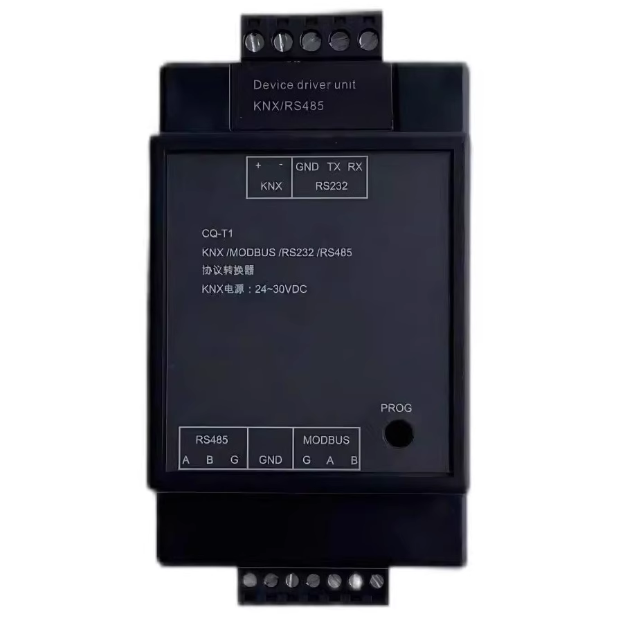
Function Introduction:
- ETS Configuration interface.
- KNX Bus direct power supply.
- support KNX <-> MODBUS Switching between host and slave modes, with maximum support 500 A register. Support any bit Length value conversion (longest 16bit). Support configuring multiple identical registers simultaneously. Only supported 0x03, 0x04, 0x06, 0x10 Instructions.
- support KNX <-> RS485 Any instruction (longest 24byte) can be converted to each other, and the conversion value can be fixed or follow 485 Data within the instruction. Maximum support 100 A command.
- support KNX <-> RS232 Any instruction (longest 24byte) can be converted to each other, and the conversion value can be fixed or follow 232 Data within the instruction. Maximum support 100 A command.
- support 100 Group logic input and output, including functions such as delay and 2-point Logic control output.
MODBUS to configure
1.Modbus Communication parameter configuration
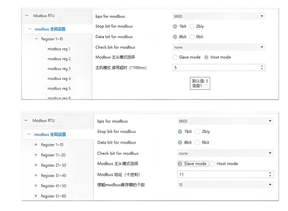
①.Bps for modbus(Set baud rate:support 2400, 9600, 19200, 38400, 56000, 115200, 128000, 256000.
②.Modbus Master slave mode selection:Slave mode: Slave mode, Host modeHost mode.
③.Modbus Address (decimal) : modbus local address setting in slave mode.
④.(master only)Host mode read/write timeout (*100ms) : in host mode, the timeout time for waiting for a reply from the slave device when reading from the slave device is set 5 represents 500ms, the minimum cannot be less than 200ms, recommended 500ms default 500ms.
⑤.enable modbus number of registers:enable register configuration
2.Modbus transfer
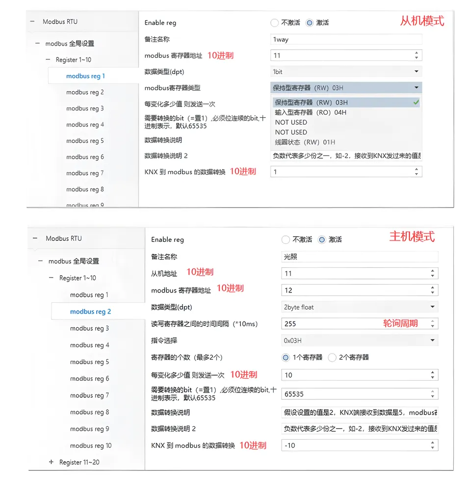
①.configuration, in host mode, all registers of the same device are placed together and arranged in ascending order. This configuration allows the gateway to read the slave registers at once instead of reading them one by one, greatly improving efficiencyactivation means enabled, not activated. Indicates not enabled.Note the nameDepending on the requirements, label what the register corresponds to.
② Enable reg: Slave address (host only
③ set the address of the slave that needs to be read): You can label what the register corresponds to according to your needs.
④ Slave address (host only)): Set the address of the slave machine that needs to be read(10Base system).
⑤ Modbus Register address: 10Base system.
⑥ Data type(dpt): KNX The data type of the object.
⑦ Modbus Register type: Hold type register-modbus The host can read and write, input type registers-modbus The host can only read the status of the coil-modbusThe host can read and write.
⑧ Time interval (host only): time interval for reading each register in host mode, default setting 0.
⑨ instruction selection (host only):instruction selection for reading registers,0X03H/0X04H/0X06H/0X10H/0X01H/0X02H/0X05H/0X0FH
⑩ number of registers (host only):can choose 12 two registers can be read together, merged and sent KNX.
- ① data format (host only):can choose high byte front and high Byte back modes, set according to the specific data format)
- ② send once for every value change:set 0 to forward regardless of the change, set 1 to forward when the value changes by 1 (suitable for switch values), set10Indicate the variation above and below the current value210Only forward it when it's time.
- ③ What needs to be converted bit:Which ones are retrieved from the register bit The value is forwarded to KNXSimilarlyKNXTransfer to modbus Register is also a value changing configuration bit, others bit The value remains unchanged. As shown in the figure below, 1 is set to represent hexadecimal 0x0001, i.e. forwarding the lowest bit data, such as the value of the register being 0x1231, KNXThen forward 1, if the value of the register is0x1230, KNXForward it0.The default value is 65535, that is 0xFFFF, forward all16bit The value.
- ④ KNX Arrived modbus Data conversion:This is a multiple used for processing data conversion, for example: assuming the set value is 2,KNXThe data received by the end is 5,modbusThe data in the register is:10;How many parts does a negative number represent-2Received KNXWhat is the value sent10SomodbusThe data in the register is 5. Application scenarios such as temperature conversion,modbus Most temperature values are accurate to one decimal place, but KNX It is accurate to two decimal places, so there is a difference between them10Multiple, can be set-10Correct the temperature value. The default value is 1, and the original data is forwarded.
RS485 to configure
RS485 Communication parameter configuration
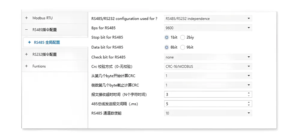
①.Bps for RS485: set up RS485 The baud rate of the bus.
②.Stop bit for RS485: Stop bit setting, only supported 1bit And 2bit.
③.Data bit for RS485: Data bit setting, only supported 8bit And 9bit.
④.Check bit for RS485: Parity setting, only supports odd parity and even parity or no parity.
⑤.Crc Verification (0 - no verification):Provide more standard searching services CRC Verify the algorithm and provide options CRC Verify the length selection of the source data.
⑥.From which one BYTE Start calculating CRC: set up CRC The starting position.
⑦.What is the last place BYTE Deadline for settlement CRC: set up CRC The end position.
⑧.Message reception timeout (N character time):RS485 The bus recognizes the end time of a frame and the time of a character *N.
⑨.RS485 Bus message sending interval (.ms) : minimum time interval for this device to send a frame of message to the bus.
⑩.RS485 number of channels enabled.
RS485 instruction configuration
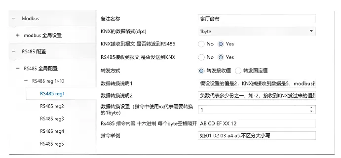
①.note name:can be marked according to needs, what corresponds to this instruction.
②.KNX data format (dpt) : KNX object data type.
③.KNX whether the message is sent after receiving it RS485.
④.RS485 whether the message is forwarded after receiving it KNX.
⑤.forwarding method:received RS485 when the bus instruction is correct, forward it to KNX value selection. When forwarding the received value, use it in the forwarding instruction XX Data on alternative locations; Forwarding fixed values,KNX send the set value
⑥.data forwarding setting:reference Modbus the seventh point of register configuration
⑦.instruction content:instruction is Input in hexadecimal format, separated by spaces between each byte , using letters XX to indicate the need to convert to KNX The data, all instruction contents are case insensitive.
RS232 to configure
RS232 The configuration and RS485 Same.
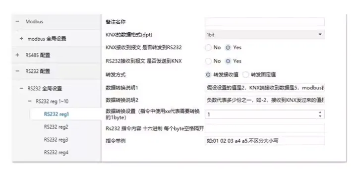
Functions to configure
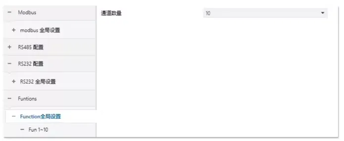
Global configuration
Number of Channels: Maximum 100 One.
Fun Parameter configuration
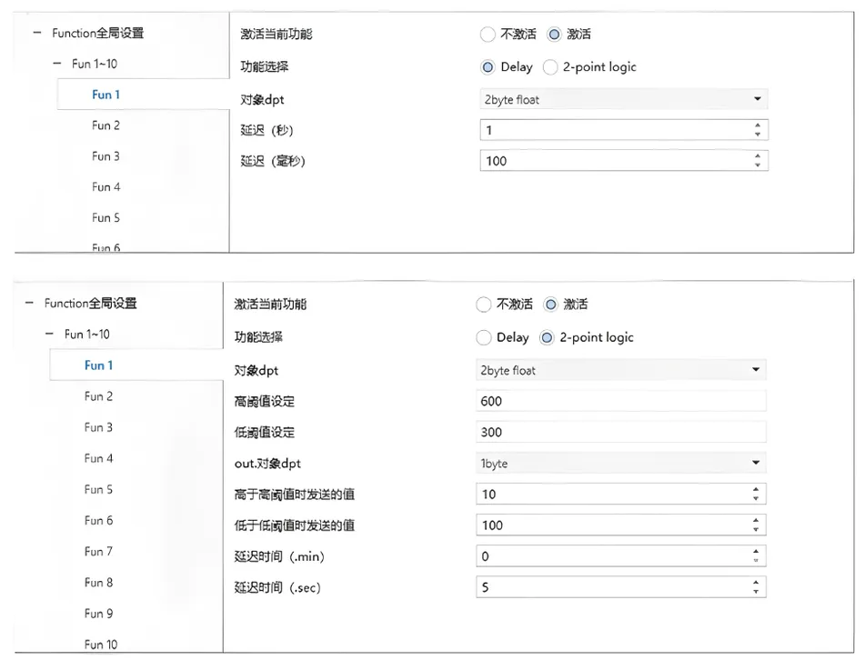
①Enable the current function Function.
②Function selection:Delay The function provides the ability to delay sending,2-point logic Provide simple functionality 2 Point control logic (above set point A triggers one operation below set point B triggers another operation).
③Object dpt: Configure the required data types.
④ (Delay)Delay (seconds):0 Representing no delay,0 ~ 255.
⑤ (Delay)Delay (milliseconds):0 Representing no delay,0 - 255.
⑥ (2-point)High threshold setting:When the input value is higher than the set value, delay the set time and send the value parameter set when it is higher than the high threshold.
⑦ (2-point)Low threshold setting:When the input value is higher than the set value, delay the set time and send the value parameter set when it is lower than the low threshold.
⑧ (2-point) Out.Object dpt: Control the data format of the output object:
⑨ (2-point)The value sent when it exceeds the high threshold:
⑩ (2-point)The value sent below the low threshold:
- (2-point)Delay time (.min) : time setting for delayed output, in minutes
- (2-point) Delay time (.sec) : time setting for delayed output, in seconds
- ) Note: When the input value is above the high threshold and a value below the high threshold is received again within the delay time, the transmission will be canceled. The function is the same when the value is below the low threshold. (1) Set hexadecimal instructions
send out
RS485/RS232 The value. KNX.
- It can also be forwarding one of the received values, using 0x12345678To indicate the value that needs to be forwarded. Converter received RS485/RS232 The message sent is: 0x12345678 At that time,KNX The address corresponding to the end 1/0/4 Will be able to 50 The location
- Forward it. xx Basic parameters and installation RS485/RS232 Electrical parameters 0xabcdef0812 project explainknx Power supply mode 1/0/5Insert directly into xx position 08 Forward it.
Basic parameters and installation
2.1 Electrical parameters
| project | Explanation |
|---|---|
| power supply method | Insert directly into KNX On the bus (21V–31V) |
| power consumption | smaller than a mobile phone charger<0.5W) |
| operating temperature | -5℃~45℃(suitable for ordinary indoor environments) |
2.2 Installation steps
- Fixed equipmentStuck in the standard35mmOn the guide rail (similar to the installation method of an electric meter box).
- Wiring:
- KNXConnect the bus with twisted pair cables (similar to Ethernet cables).
- RS485/RS232Connect the equipment with shielded twisted pair cables (anti-interference).
- indicator light:
- Green light constantly on: power supply is normal.
- Red light flashing: currently being configured.
Examples of practical application scenarios
Scenario 1: Intelligent building lighting
- Equipment: KNX Lighting system + MODBUS Human body sensors.
- Logic:
- Sensors detect unmanned → Send a signal to the gateway.
- Gateway latency30Seconds → ThroughKNXTurn off the lights.
Scenario 2: Industrial temperature control
- Equipment: RS485 Temperature sensor + KNX Air conditioning controller.
- Logic:
- Sensor reporting28℃ → Gateway forwarding toKNX.
- KNX Judgment >25℃ → send out“turn the air conditioner on”Instructions.
Common questions and answers
Q1What should I do if the indicator light doesn't light up?
- CheckKNXIs the bus power supply normal? (21V–31V) .
- Confirm if the wiring is loose.
Q2: Data forwarding is unsuccessful?
- Check if the baud rate and checksum are consistent with the device.
- Confirm if the position in the instruction is correct.
XX: Logical rules are not triggered?
Q3Check if the threshold is set reasonably (such as writing incorrectly as
- Confirm if the address of the output object is correct.“>30”Technical parameter summary table“<30”) .
- Project
Parameters
| Power supply voltage | Bus direct power supply) |
|---|---|
| Maximum power consumption | 21–31V DC (KNX(Ultra energy-efficient) |
| Support agreement | <0.5WNumber of logical channels |
| Supported Protocols | KNX, MODBUS, RS485, RS232 |
| Number of logical channels | 100Group (meeting complex automation requirements) |


Leave a Reply