
1、 Equipment Overview
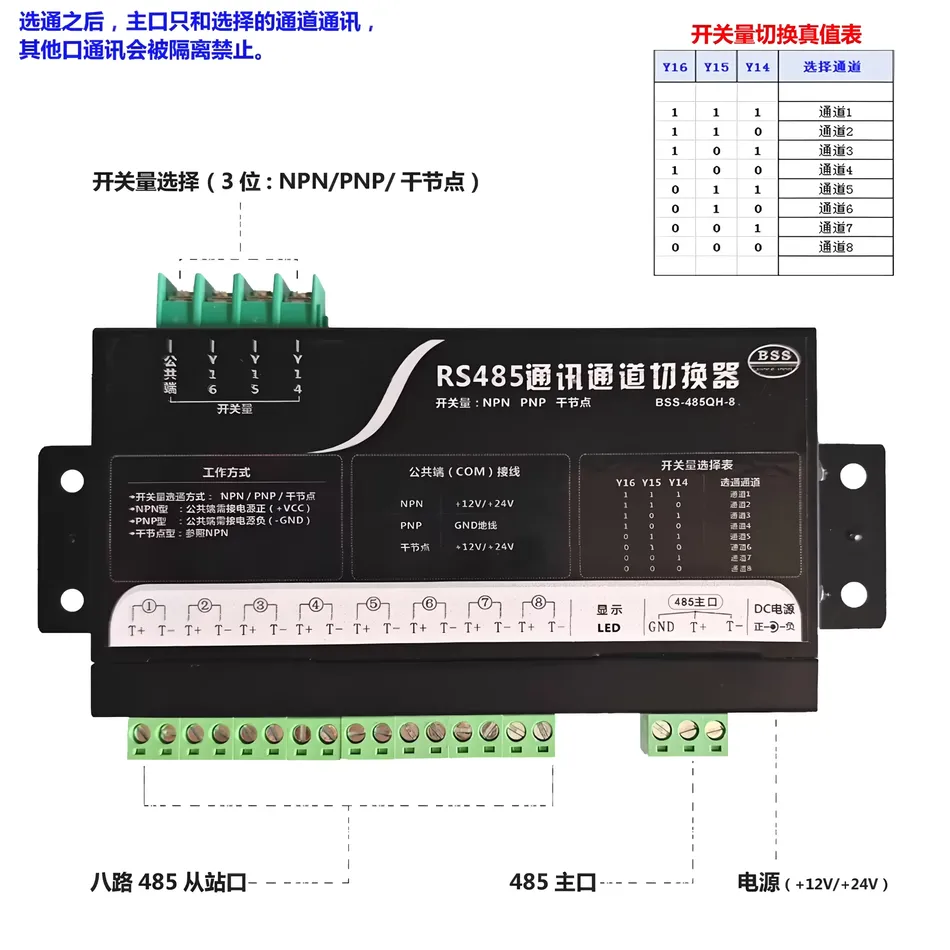
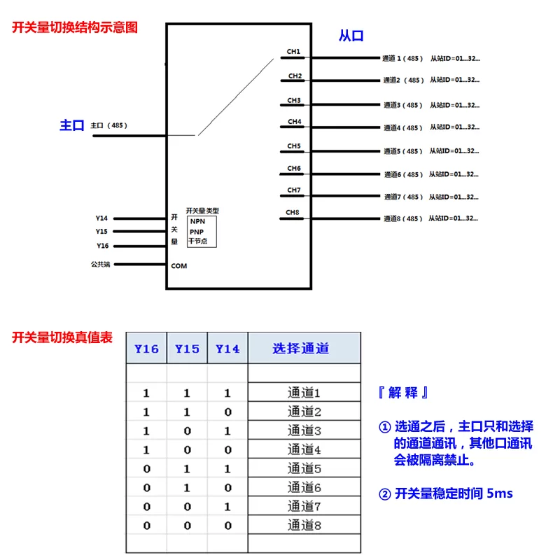
The device model isBSS-485QH-8It is aEight channelsRS485Communication channel switch. Its core function is to dynamically select the communication between the master station port and one of the eight slave station ports through an external input of a 3-digit switch signal, while isolating the other seven ports to avoid bus conflicts. Main characteristics:
- 8Road station portCan connect 8 independent onesRS485Bus.
- 1Road master station portConnect the main control device (such as industrial computer).PLCSwitching control
- : ThroughSelect the channel based on the level status of the three terminals (Y14, Y15, Y16).0/1Electrical isolation
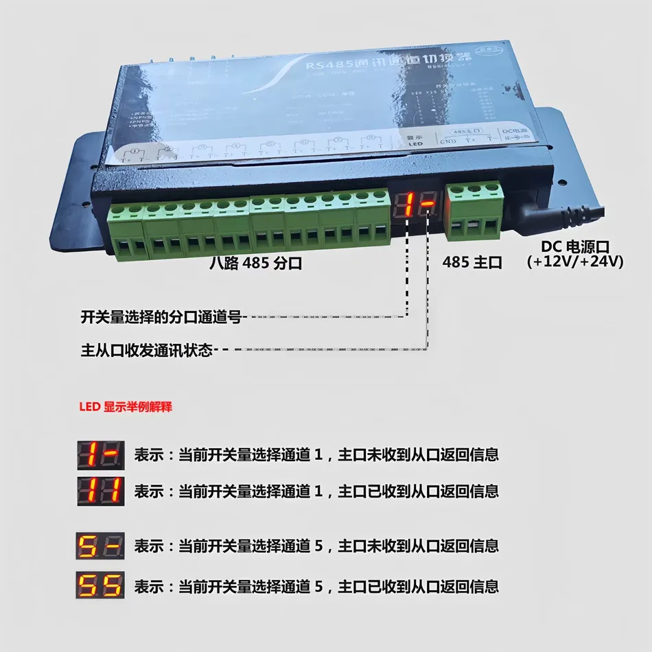
- After being selected, the main port only communicates with the selected channel, and other channels are prohibited to ensure bus stability.Status indication
- : Equipped withDisplay screen, real-time display of current channel number and master-slave communication status.LEDFlexible power supply
- : SupportOrDC +12V Wide voltage power input. +24V2、 Core working principle: selection of switch channel
The most notable feature of this device is the adoption of
Switching signalRather than software instructions for channel switching, this makes it particularly suitable for use byDirectly controlled scenarios.PLCDefinition of control signal:
1. The device provides three switch control terminals: . The level status of each terminal (Y14, Y15, Y16represents high level,“1”represents low level) together forms a 3-digit binary number used to select the target channel.“0”Switching truth table for switch values:
2. The channel selection strictly follows the following truth table. Users make changes The combination of voltage levels can accurately select channels 1 to 8.Y16, Y15, Y14Selected channel
| Y16 | Y15 | Y14 | Channel |
|---|---|---|---|
| 1 | 1 | 1 | Channel1 |
| 1 | 1 | 0 | Channel2 |
| 1 | 0 | 1 | Channel3 |
| 1 | 0 | 0 | Channel4 |
| 0 | 1 | 1 | Channel5 |
| 0 | 1 | 0 | Channel6 |
| 0 | 0 | 1 | Channel7 |
| 0 | 0 | 0 | Switch type and wiring:8 |
3. The device is compatible with three common types of switch signals, which can be set through the hardware selection area: Leakage type output, common terminal (
- NPN) connected to the positive pole of the power supply (COM: source type output, common terminal (+V) .
- PNP) connected to the power supply ground (COMdry nodeGND) .
- : passive contact signal (such as relay contact), directly connected to the control terminal andEnd.COMThe stability time of the switch quantity is approximately
This means that a brief delay is required after switching the switch quantity to ensure stable channel switching.5ms3、 Work status indication
3、 Work status indication
The device passes through a two digitLEDThe display screen provides intuitive status feedback, and its display format is: 通道号.状态码.
- Channel number: Display the selected channel of the current switch value (1-8) .
- Status code: Display the communication status between the master and slave ports.
-
0: Indicates that the channel has been selected, but the master port has not received the response information returned by the slave station.orand other numbers -
3: Indicates that the channel has been selected, and the master port has received the response information returned by the slave station. The number specifically represents the communication quality or signal strength.5Example:Display: Channel 1 is currently selected, and the master device is sending instructions or the slave device is not responding.Display: Channel 5 is currently selected, and communication with the slave device on channel 5 is normal. 4. Typical application scenarios: This switch is very suitable for the following scenarios: 1. One master multiple slave system expansion1. One unit
-
Need When polling access exceeds the address limit (usually
- ) for slave devices, they can be grouped and connected to 8 channels for time-sharing access through a switch.
1.0Multi bus isolation - In complex electromagnetic environments, devices from different regions are assigned to different buses and isolated through switches to reduce mutual interference.
5.5Redundant backup system
When a bus or a group of slave devices fails, it can quickly switch to a backup bus channel to improve system reliability.
5、 Summary
- This is based on switch quantity controlChannel switch, with its hardware level switching reliability, ease of operation, and intuitive status indication, is a multi branchPLCThe internet provides an efficient and cost-effective centralized management solution. It perfectly bridges the fields of digital quantity control and serial communication, making it particularly suitable for use inRS485Played in the dominant automation control system32Traffic Commander
- The role is to achieve orderly multi-channel communication management.In complex electromagnetic environments, devices from different regions are assigned to different buses and isolated through switches to reduce mutual interference.
- Redundant backup systemWhen a bus or a group of slave devices fails, it can quickly switch to a backup bus channel to improve system reliability.
5、 Summary
This switch based controlRS485Channel switch, with its reliability in hardware level switching, ease of operation, and intuitive status indication, is designed for multi branch switchingRS485The internet provides an efficient and cost-effective centralized management solution. It perfectly bridges the fields of digital quantity control and serial communication, making it particularly suitable for use inPLCPlayed in the dominant automation control system“Traffic Commander”The role is to achieve orderly multi-channel communication management.


Leave a Reply