
1. Overview of RGB Settings (Color Wheel) Function
RGB Settings (Color Wheel) can be applied to the RGB dimming function.
2. How to Add RGB Settings (Color Wheel)
Click the general template in the toolbox, and then click the RGB Settings (Color Wheel) icon to add RGB Settings (Color Wheel), as shown in Figure 2.1.
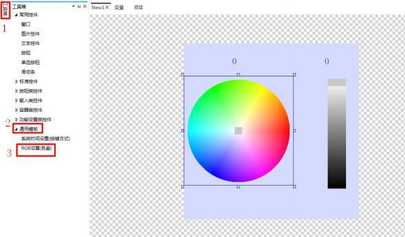 Figure 2.1 Adding Controls
3. How to Replace Images
Select the circular color picker, click Image in the property window on the right side → click the slider → select the image → click "...", to replace the image of the circular color picker's slider, as shown in Figure 3.1.
Note: The replacement of the slider image for the bar color picker is the same.
Figure 2.1 Adding Controls
3. How to Replace Images
Select the circular color picker, click Image in the property window on the right side → click the slider → select the image → click "...", to replace the image of the circular color picker's slider, as shown in Figure 3.1.
Note: The replacement of the slider image for the bar color picker is the same.
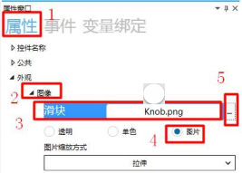 Figure 3.1 Image Replacement
Click the simulation run button to pop up the simulation run window, as shown in Figure 3.2.
Figure 3.1 Image Replacement
Click the simulation run button to pop up the simulation run window, as shown in Figure 3.2.
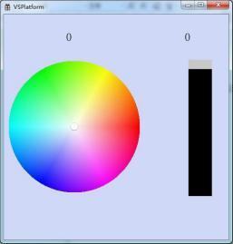 Figure 3.2 Simulation Demonstration
4. How to Set Miscellaneous Items
Select the circular color picker and click the button under "Misc. - Trigger Mode" to pop up a dropdown box. There are two trigger modes: continuous trigger and trigger on release. If you choose continuous trigger, the trigger will be activated continuously when the slider is dragged. If you choose trigger on release, the trigger will be activated at the moment the slider is released after being dragged, as shown in Figure 4.1.
Figure 3.2 Simulation Demonstration
4. How to Set Miscellaneous Items
Select the circular color picker and click the button under "Misc. - Trigger Mode" to pop up a dropdown box. There are two trigger modes: continuous trigger and trigger on release. If you choose continuous trigger, the trigger will be activated continuously when the slider is dragged. If you choose trigger on release, the trigger will be activated at the moment the slider is released after being dragged, as shown in Figure 4.1.
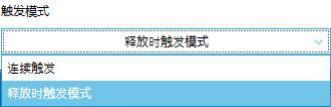 Figure 4.1 Set Trigger Mode
Note: The miscellaneous settings for the bar color picker are the same as those for the circular color picker.
5. How to Set Variable Binding
1. How to Add a Custom Variable
Click "Variables" in the menu bar to pop up the variable window, click Custom Variable → click Add → set the variable type to "unsigned integer" → set the maximum value to "4294967295", as shown in Figure 5.1.
Figure 4.1 Set Trigger Mode
Note: The miscellaneous settings for the bar color picker are the same as those for the circular color picker.
5. How to Set Variable Binding
1. How to Add a Custom Variable
Click "Variables" in the menu bar to pop up the variable window, click Custom Variable → click Add → set the variable type to "unsigned integer" → set the maximum value to "4294967295", as shown in Figure 5.1.
 Figure 5.1 Add Custom Variable
2. How to Set Variable Binding
Select the bar color picker and click Variable Binding in the property window on the right → click Add → set the bound control property to "Color Value" → set the data source to "Var1" → set the conversion mode to "Bidirectional" → set the conversion method to "Default", as shown in Figure 5.2.
Figure 5.1 Add Custom Variable
2. How to Set Variable Binding
Select the bar color picker and click Variable Binding in the property window on the right → click Add → set the bound control property to "Color Value" → set the data source to "Var1" → set the conversion mode to "Bidirectional" → set the conversion method to "Default", as shown in Figure 5.2.
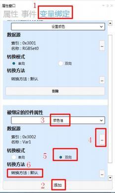 Figure 5.2 Bar Color Picker Variable Binding
3. How to Add a Text Control
Click the text icon in the common control module to add two text controls to display the numerical values corresponding to the selected color, as shown in Figure 5.3.
Figure 5.2 Bar Color Picker Variable Binding
3. How to Add a Text Control
Click the text icon in the common control module to add two text controls to display the numerical values corresponding to the selected color, as shown in Figure 5.3.
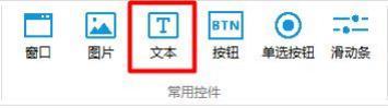 Figure 5.3 Add Text Control
4. How to set variable binding for the text control
Select the text control (this text control displays the color-corresponding numerical value of the circular color picker), click on "Variable Binding" in the property window on the right → click "Add" → the bound control property is "Text 1" → the data source is "RGBSet0" → the conversion mode is "One-way" → the conversion method is "Default", as shown in Figure 5.4.
Figure 5.3 Add Text Control
4. How to set variable binding for the text control
Select the text control (this text control displays the color-corresponding numerical value of the circular color picker), click on "Variable Binding" in the property window on the right → click "Add" → the bound control property is "Text 1" → the data source is "RGBSet0" → the conversion mode is "One-way" → the conversion method is "Default", as shown in Figure 5.4.
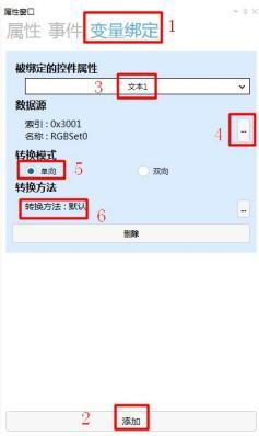 Figure 5.4 Variable Binding
Select the text control (this text control displays the color-corresponding numerical value of the bar color picker), click on "Variable Binding" in the property window on the right → click "Add" → the bound control property is "Text 1" → the data source is "Var1" → the conversion mode is "One-way" → the conversion method is "Default", as shown in Figure 5.5.
Figure 5.4 Variable Binding
Select the text control (this text control displays the color-corresponding numerical value of the bar color picker), click on "Variable Binding" in the property window on the right → click "Add" → the bound control property is "Text 1" → the data source is "Var1" → the conversion mode is "One-way" → the conversion method is "Default", as shown in Figure 5.5.
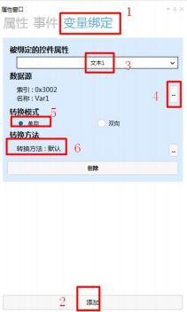 Figure 5.5 Variable Binding
6. How to set circular color picker to send custom protocol
1. How to add events
Select the circular color picker and click on "Events" in the property window on the right to add events, as shown in Figure 6.1.
Figure 5.5 Variable Binding
6. How to set circular color picker to send custom protocol
1. How to add events
Select the circular color picker and click on "Events" in the property window on the right to add events, as shown in Figure 6.1.
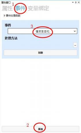 Figure 6.1 Add Event
2. How to set the processing method
Custom protocol allows users to use other protocols in the project, such as the Modbus protocol.
Click on the lower right corner of the processing method
Figure 6.1 Add Event
2. How to set the processing method
Custom protocol allows users to use other protocols in the project, such as the Modbus protocol.
Click on the lower right corner of the processing method
 , and a processing method window will pop up. Select "Command Send" → choose "Custom Protocol" to send serial port commands → set the command
, as shown in Figure 6.2.
, and a processing method window will pop up. Select "Command Send" → choose "Custom Protocol" to send serial port commands → set the command
, as shown in Figure 6.2.
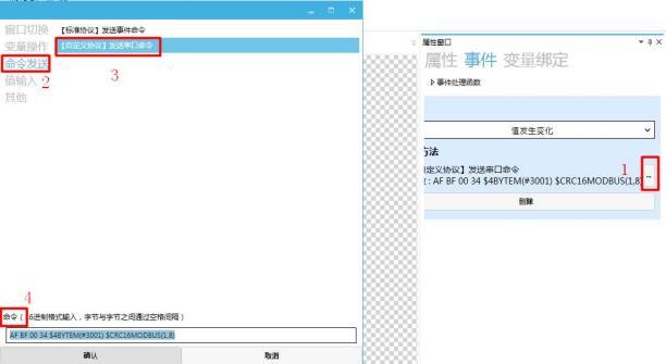 Figure 5.2 "Custom Protocol" sending serial port commands
Note: When clicking the input box for "Custom Protocol" to send serial port commands, a custom command function description window will pop up, as shown in Figure 6.3.
Figure 5.2 "Custom Protocol" sending serial port commands
Note: When clicking the input box for "Custom Protocol" to send serial port commands, a custom command function description window will pop up, as shown in Figure 6.3.
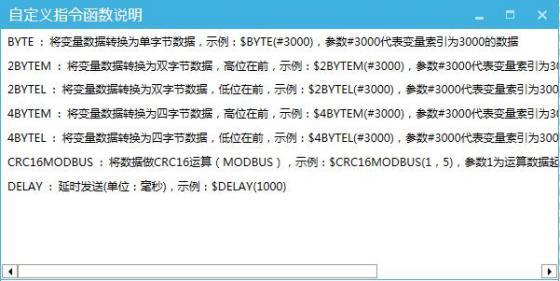 Figure 6.3 Custom Command Function Description Window
3. How to view the standard protocol commands sent by the circular color picker
When sending a custom protocol command "AF BF 00 34 $4BYTEM(#3001) $CRC16MODBUS(1,8)", click the simulation run button
Figure 6.3 Custom Command Function Description Window
3. How to view the standard protocol commands sent by the circular color picker
When sending a custom protocol command "AF BF 00 34 $4BYTEM(#3001) $CRC16MODBUS(1,8)", click the simulation run button
 ,
and slide the slider in the circular color picker on the simulation interface to view the sent commands, as shown in Figure 6.4.
,
and slide the slider in the circular color picker on the simulation interface to view the sent commands, as shown in Figure 6.4.
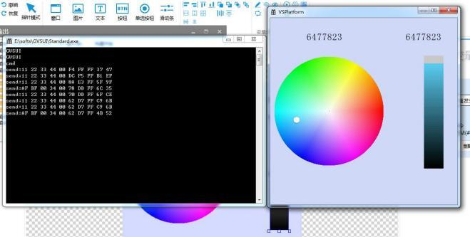 Figure 6.4 Sending "Custom Protocol" Commands
7. How to set up custom protocol sending with the bar color picker
1. How to add events
Select the bar color picker, and the specific operation is the same as that of the circular color picker.
2. How to set the processing method
The specific settings are the same as those for the circular color picker.
3. How to view the standard protocol commands sent by the bar color picker
When sending a custom protocol command "11 22 33 44 $4BYTEM(#3002) $CRC16MODBUS( 1,8) ", click the simulation run button
Figure 6.4 Sending "Custom Protocol" Commands
7. How to set up custom protocol sending with the bar color picker
1. How to add events
Select the bar color picker, and the specific operation is the same as that of the circular color picker.
2. How to set the processing method
The specific settings are the same as those for the circular color picker.
3. How to view the standard protocol commands sent by the bar color picker
When sending a custom protocol command "11 22 33 44 $4BYTEM(#3002) $CRC16MODBUS( 1,8) ", click the simulation run button
 ,
and slide the slider in the bar color picker in the simulation interface to view the sent command, as shown in Figure 7.4.
,
and slide the slider in the bar color picker in the simulation interface to view the sent command, as shown in Figure 7.4.
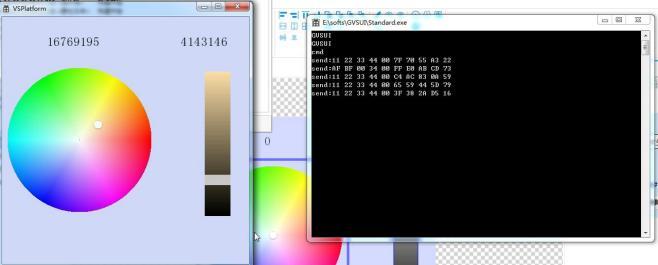 Figure 7.1 Sending [Custom Protocol] Command
8. How to set the color of the color wheel through custom parsing
8.1 How to set the color of the circular color picker through custom parsing
1. How to add custom parsing
Click on the project to pop up the project window, click on "Protocol Settings" → set the protocol type to "Custom Protocol" → click on "Custom Protocol Parsing Settings" → a parsing settings window pops up → click "Add" to pop up a custom parsing settings window, where you can add a custom protocol parsing according to your needs and requirements, as shown in Figure 8.1.
Figure 7.1 Sending [Custom Protocol] Command
8. How to set the color of the color wheel through custom parsing
8.1 How to set the color of the circular color picker through custom parsing
1. How to add custom parsing
Click on the project to pop up the project window, click on "Protocol Settings" → set the protocol type to "Custom Protocol" → click on "Custom Protocol Parsing Settings" → a parsing settings window pops up → click "Add" to pop up a custom parsing settings window, where you can add a custom protocol parsing according to your needs and requirements, as shown in Figure 8.1.
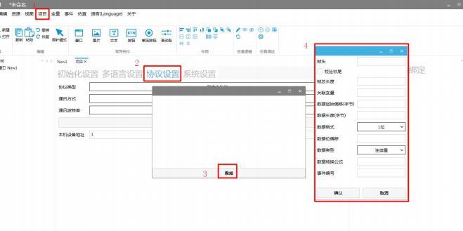 Figure 8.1 Add Custom Protocol Parsing
2. How to set custom parsing
Set the frame header to "00 00 00 00" → check the "Verify Frame Tail" box → set the frame tail to "88 88" → set the total frame length to "10" → set the associated variable index to "3001" → set the data start offset byte to "5" → set the data length (in bytes) to "4" → set the data format to "4 bytes (with high-order bytes first)" → set the data type to "Continuous" → click "Confirm", as shown in Figure 8.2.
Figure 8.1 Add Custom Protocol Parsing
2. How to set custom parsing
Set the frame header to "00 00 00 00" → check the "Verify Frame Tail" box → set the frame tail to "88 88" → set the total frame length to "10" → set the associated variable index to "3001" → set the data start offset byte to "5" → set the data length (in bytes) to "4" → set the data format to "4 bytes (with high-order bytes first)" → set the data type to "Continuous" → click "Confirm", as shown in Figure 8.2.
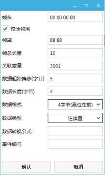 Figure 8.2: Setting Custom Parsing
3. Simulation Debugging
For specific simulation debugging operations and methods, refer to the "Simulation Debugging User Manual". As shown in Figure 8.3, send the command "00 00 00 00 00 9A FF 9A 88 88" through the serial port debugging tool software, and move the slider to the position of "10157978".
Figure 8.2: Setting Custom Parsing
3. Simulation Debugging
For specific simulation debugging operations and methods, refer to the "Simulation Debugging User Manual". As shown in Figure 8.3, send the command "00 00 00 00 00 9A FF 9A 88 88" through the serial port debugging tool software, and move the slider to the position of "10157978".
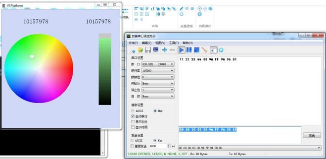 Figure 8.3: Simulation Demonstration
8.2 How to Set Color Picker Colors Through Custom Parsing
1. How to Add Custom Parsing
Click on the project to pop up the project window, click on "Protocol Settings" → set the protocol type to "Custom Protocol" → click on "Custom Protocol Parsing Settings" → a parsing settings window pops up → click "Add" to pop up a custom protocol parsing settings window, where you can add a custom protocol parsing according to your needs and requirements, as shown in Figure 8.4.
Figure 8.3: Simulation Demonstration
8.2 How to Set Color Picker Colors Through Custom Parsing
1. How to Add Custom Parsing
Click on the project to pop up the project window, click on "Protocol Settings" → set the protocol type to "Custom Protocol" → click on "Custom Protocol Parsing Settings" → a parsing settings window pops up → click "Add" to pop up a custom protocol parsing settings window, where you can add a custom protocol parsing according to your needs and requirements, as shown in Figure 8.4.
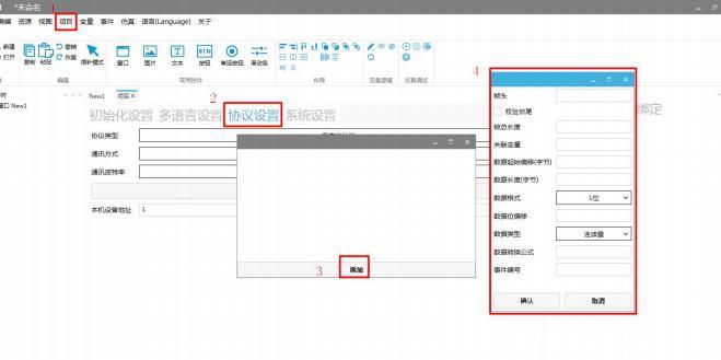 Figure 8.4: Adding Custom Protocol Parsing
2. How to Set Custom Parsing
Set the frame header to "11 22 33 44" → check the "Verify Frame Tail" box → set the frame tail to "11 22" → set the total frame length to "10" → set the associated variable index to "3002" → set the data start offset byte to "5" → set the data length (in bytes) to "4" → set the data format to "4 bytes (with high-order bytes first)" → set the data type to "Continuous" → click "Confirm", as shown in Figure 8.5.
Figure 8.4: Adding Custom Protocol Parsing
2. How to Set Custom Parsing
Set the frame header to "11 22 33 44" → check the "Verify Frame Tail" box → set the frame tail to "11 22" → set the total frame length to "10" → set the associated variable index to "3002" → set the data start offset byte to "5" → set the data length (in bytes) to "4" → set the data format to "4 bytes (with high-order bytes first)" → set the data type to "Continuous" → click "Confirm", as shown in Figure 8.5.
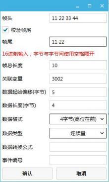 Figure 8.5 Set Custom Resolution
4. Simulation Debugging
For specific simulation debugging operations and methods, please refer to the "Simulation Debugging User Manual", as shown in Figure 8.6. Use the serial port debugging tool software to send the command "11 22 33 44 00 4E 82 4E 11 22", and move the slider to the position of "5145166".
Figure 8.5 Set Custom Resolution
4. Simulation Debugging
For specific simulation debugging operations and methods, please refer to the "Simulation Debugging User Manual", as shown in Figure 8.6. Use the serial port debugging tool software to send the command "11 22 33 44 00 4E 82 4E 11 22", and move the slider to the position of "5145166".
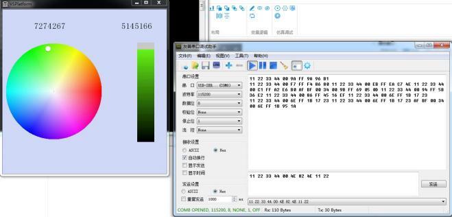 Figure 8.6 Simulation Demonstration
If you find it helpful, please give a thumbs up


Leave a Reply