

The Modbus protocol has only one master stationThere can be 1-247 slave stations. This protocol supports traditional RS-232, RS-422, RS-485, and Ethernet devices, and many industrial devices, including PLCs, DCS, smart meters, etc., are using Modbus protocol as their communication standard.
When the controller is set to communicate in RTU mode on a Modbus network, each 8Bit byte in the message is transmitted according to its original value without processing, such as 63H. The RTU will directly send 01100011. The main advantage of this method is that there is no interval between data frame transmissions, and the density of transmitted data at the same baud rate is higher than ASCII, resulting in faster transmission speed.
IIModbus RTU master station command
1The Modbus library instructions are shown in Figure 1, where Master is the 0 port of the master station, Master2 is the 1 port of the master station, Slave is the slave station, and the slave station only has 0 ports.
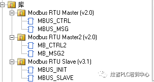
Figure 1
2.Siemens Modbus Library Master StationThe main station definition parameters of MBUS_CTRL are shown in Figure 2.
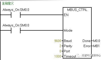
Figure 2
The symbols in Figure 2 are explained as follows:
EN: Always enabled
MODE: Allow Modbus communication
Baud: Communication rate, baud rate (master-slave consistent), default 9600
Parity: parity check, 0 no check, 1 odd check, 2 even check (master-slave consistency), default even check
Port: Communication port, 0-port built-in, 1-port expansion (CM01 signal board)
Timeout: Maximum waiting time unit: ms
Done: Completion position
Error: Error code (when an error occurs, you can check the corresponding error code in the software help)
The reading and writing parameters of the master station information of Siemens Modbus library master station MBUS_SSG are shown in Figure 3
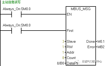
Figure 3
The symbols in Figure 3 are explained as follows:
En: Enable
First: First scan triggered by edge
Slave: Slave address (1-247 main station defaults to station 2, slave addresses except for 2)
RW: Read and write operations, 0 read, 1 write
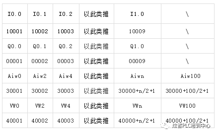
Addr: Read and write address function code
Count: Quantity
Dataptr: Data pointer (default refers to the main station and is displayed in bytes)
Done: Completion position
Error: Error byte (when an error occurs, you can check the corresponding error code in the software help)
STEP7_Sicro/WIN Smart and S7_200SmartCPU support two types of Modbus RTU master stations. For a single Modbus RTU master station, the instructions MBUS_CTRL and MBUS_SG are used for 0-port communication. For the second Modbus RTU master station, use the instructions MBUS_CTRL2 and MBUS_SSG2 for 1-port communication. If you use two Modbus master stations in the project, make sure that MBUS_CTRL and MB_CTRL2 use different port numbers.
MBUS_CTRL is written in the master station, regardless of how many slave stations there are, only once. MBUS_SSG is written in the master station, for example, if there is a slave station, the master and slave control each other, requiring 2 instructions, one read and one write. If there are multiple slave stations, multiple read and write instructions are written.
IIIModbus RTU Slave Command
- The slave definition parameters of Siemens Modbus library slave MBUS_CTRL are shown in Figure 4.
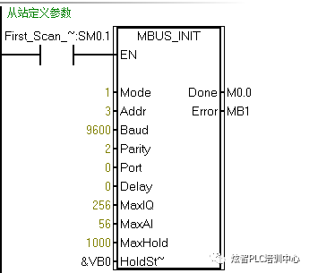
Figure 4
The symbols in Figure 4 are explained as follows:
En enables edge triggering
Mode allows Modbus communication
Addr slave station address (1-147)
Baud communication rate baud rate (master-slave consistent) default 9600
Parity Parity check 0 no check, 1 odd check, 2 even check (master-slave consistency) default even check
Port communication port 0 comes with built-in port
Delay Delay
MaxIQ Maximum Input/Output Points 256
MaxAI maximum analog input 56
Maxhold Maximum Cache Area
Holdstart maximum cache starting address
Done completion position
Error byte
Done completion position
Error byte
2.The slave response parameters of Siemens Modbus library slave MBUS_SLAVE are shown in Figure 5.
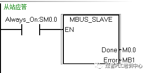
Figure 5
4Communication program writing
Example of Communication between Two PLCs Controlled by Modbus RTU
The two PLCs of Modbus RTU use point I to control point Q with each other. The master station program is shown in Figure 6, and the slave station program is shown in Figure 7. When writing a slave program, it is important to note that the slave definition needs to be triggered by edges. Remember to change the slave PLC station address in the system block.
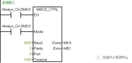
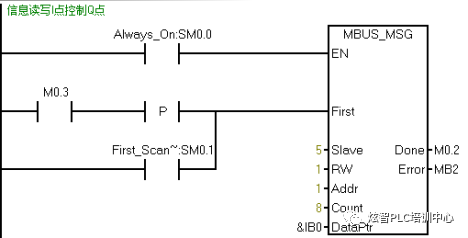
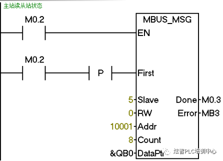
Figure 6
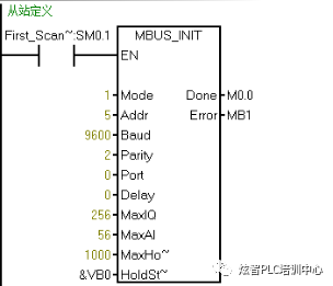
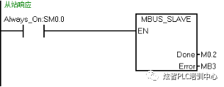
Figure 7
Example of star delta communication between two PLCs in Modbus RTU
Two PLCs, the master station controls the start and stop of the star delta of the slave stationThe master station IW0 controls the slave station VW0 (starting from I0.0 to V0.0 and stopping from I0.1 to V0.1). The master station program is shown in Figure 1-1 and Figure 1-2, and the slave station program is shown in Figure 1-3, Figure 1-4, Figure 1-5, Figure 1-6, Figure 1-7, and Figure 1-8.
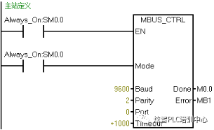
Figure 1-1
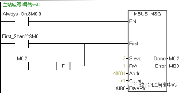
Figure 1-2
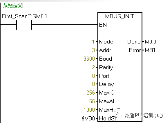
Figure 1-3
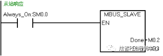
Figure 1-4
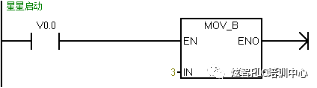
Figure 1-5
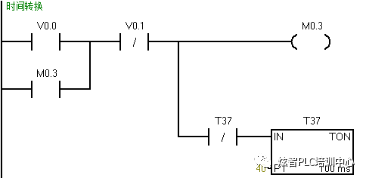
Figure 1-6
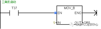
Figure 1-7
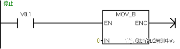
Figure 1-8
Modbus RTU Three PLC Star Triangle Communication Example
- SantaiThe PLC communication master station, the 3rd slave station, and the 4th slave station mutually control the start and stop of the two motors between the 3rd and 4th stations, as shown in Figure 2-1. The control program is shown in Figure 2-2, Figure 2-3, Figure 2-4, Figure 2-5, Figure 2-6, and Figure 2-7.
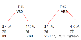
Figure 2-1
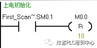
Figure 2-2
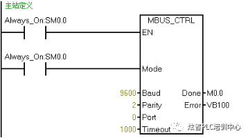
Figure 2-3
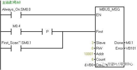
Figure 2-4
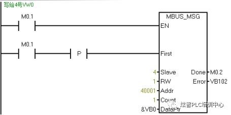
Figure 2-5
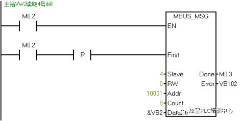
Figure 2-6
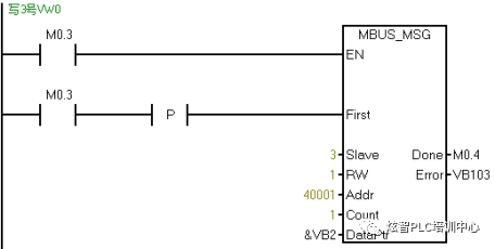
Figure 2-7
2.Three PLC communication master stations, the 3rd and 4th slave stations control the start and stop of two motors with each other. The control program for the 3rd slave station is shown in Figure 2-8, Figure 2-9, and Figure 2-10.
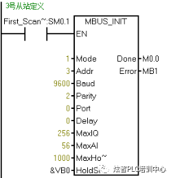
Figure 2-8
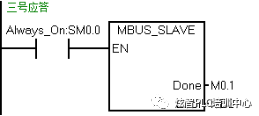
Figure 2-9
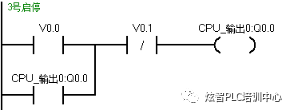
Figure 2-10
3.SantaiThe PLC communication master station, the 3rd slave station, and the 4th slave station mutually control the start and stop of the two motors between the 3rd and 4th slave stations. The control program for the 4th slave station is shown in Figure 2-11, Figure 2-12, and Figure 2-13.
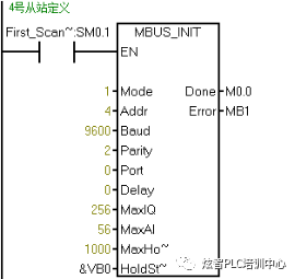
Figure 2-11
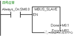
Figure 2-12
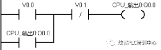
Figure 2-13
It is worth noting that remember to change the addresses of Station 3 and Station 4 within the system block, triggered by the edge defined by the station. Finally, remember to set the allocation of inventory storage areas in the program block as shown in Figure 2-14.
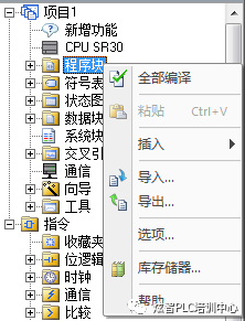
Figure 2-14


Leave a Reply