
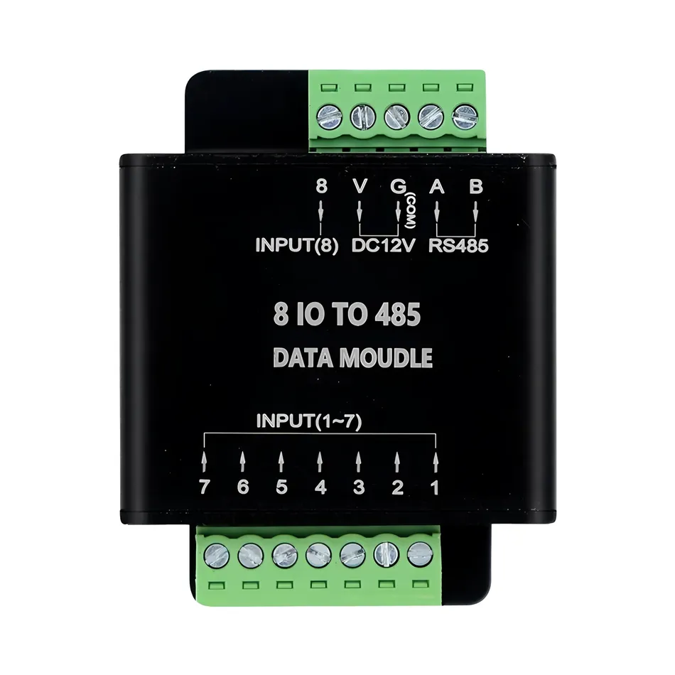
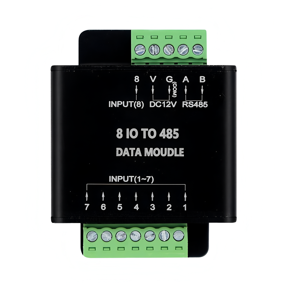
I. Product Overview
This product is an intelligent conversion module that converts dry contact signals into custom bus data, supporting the use of dry contact switchesOn/Off, Single Click, Double ClickSend multiple sets of custom commands to control third-party devices (such as lighting, sensors, fans, valves, etc.) and achieve personalized scene linkage. Suitable for home decoration, workwear, municipal, industrial, agricultural and other scenarios, supporting RS485 bus communication and multiple extension protocols (requiring conversion modules).
II. Product Features
- Compact Design: Size 46 × 57mm, can be embedded into an 86 bottom box.
- Stable and reliable: Each input optocoupler is isolated, with strong anti-interference ability, and supports weak current signal transmission over a 300 meter Ethernet cable.
- Flexible Configuration:
- Supports address modification and custom baud rate (1200-115200bps).
- Each switch supports sending 4 sets of custom data (on/off/click/double-click).
- Supports delay control of 0.1-399 seconds.
- Bidirectional Communication: Interface status can be queried, and local control can still be achieved even when the network is disconnected.
- Security Protection: Supports button locking (single or global) to prevent accidental touch.
- Strong Scalability: Can connect to protocols such as KNX, CAN, LoRa, WiFi, etc. (requires conversion module).
III. Technical Parameters
| Project | Parameters |
|---|---|
| Product Model | 8-Channel IO to 485 Module |
| power input | DC 12-24V |
| Operating Temperature | -10°C ~ 50°C |
| communication interface | RS485 (default), dry contact |
| Baud rate | 1200-115200bps (default 9600 8 N 1) |
| Shell material | Aluminum alloy |
| Size | 46×57mm |
| weight | 55g |
4, Installation and wiring
- Power connectionConnect a DC 12-24V power supply (pay attention to the positive and negative poles).
- Dry contact input: Connect the external switch signal to the 1-8 input terminals of the module.
- RS485 output: A/B terminals are connected to the bus network (terminal resistance matching is required).
- Grounding protection: Ensure good grounding of the equipment to avoid interference.
V. Function Configuration and Instruction Description
1. Address Modification
- Instruction Format:
旧地址(5字节) + F8 E7 D6(固定码) + 新地址(5字节) - Example:
1A 13 24 56 91 F8 E7 D6 1A 33 57 26 81
Change the address from 1A13245691 to 1A33572681.
2. Status Query
- Send Instruction:
设备地址(5字节) + 86 86 86 0F - Feedback Example:
XX XX XX XX XX 00 01 00 01 00 00 00 01 01 01 00 01 00 00 00 01 0F(Fixed)
represents 8 states in sequence: Off, On, Off, On, Off, Off.
3. Single key lock
- Instruction format:
设备地址(5字节) + FF 00 32 + 路数(00-07) + 状态(00锁定/01解锁) - Example:
1A 18 06 10 59 FF 00 32 00 00
Lock the first button.
4. Global Lock Mode
- Instruction Format:
设备地址(5字节) + FF 00 33 20 + 状态(00锁定/01解锁) - Example:
1A 18 06 10 59 FF 00 33 20 00
Lock all channel keys.
VI.Software and User Manual
User Manual
VII. Precautions
- Do not exceed 24V power supply voltage to avoid damaging the module.
- The RS485 bus needs to use shielded twisted pair, and the terminal equipment should be equipped with a 120 Ω resistor.
- It is recommended to test signal stability during long-distance transmission.
- Ensure that there are no conflicts on the bus when modifying the address. After the lock function is enabled, an unlock command needs to be sent to restore the operation.
- After the locking function is enabled, an unlock command must be sent to restore the operation.
8. After sales service
- Warranty period: 1 year (non human damage).
- Technical Support: 18801054468
Product Purchase:https://item.taobao.com/item.htm?ft=t&id=575621597516


Leave a Reply