
Description
1. Product Features
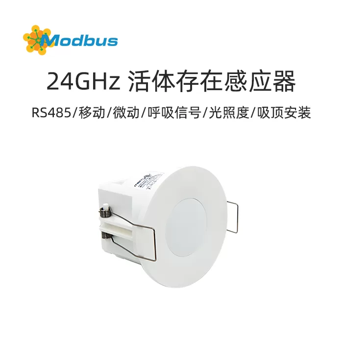
This product is an embedded independent installation wireless RS485 communication sensor with functions of mobile, micro motion, and respiratory detection+light intensity sensing data acquisition. It has a built-in MCU serial port and RS485 module for control and data exchange. The product uses a 24. 125GHz millimeter wave presence sensing module, the latest large beam angle bracket antenna technology, and a new software algorithm. The product's feature is to achieve live presence detection and light intensity information access to the RS485 system as a data acquisition unit.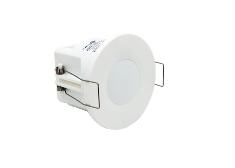 1) Using live detection technology, it can accurately detect movement, micro movement, and respiratory signals, achieving true presence detection.
2, Product specifications and parameters
| Working Voltage | 12-24V DC | |
| operating current | @ 12Vdc : 30mA max | |
| Communication method | RS485 | |
| Microwave operating frequency | 24GHz-24.25GHz ISM frequency band | |
| Microwave transmission power | 3dBM Max. | |
| 3db beam angle | 100 ° (XZ plane) 100 ° (YZ plane) | |
| Detection range (radius) | Mobile detection distance: 3-4m Micro motion detection distance: 3-4m Respiratory detection distance: 2.5-3m | |
| Sensitivity adjustable level | 0% -100% (MH10 remote control settings 25% 50% 75% 100%; Serial port setting 0% -100%) | |
| Hold time | 30s/1min/2min/3min/5min/10min/20min/30min (compatible with MH10 remote control or serial port setting 2S-7200S) Note: The detection function should be set for at least 30S | |
| Illumination setting (Daylight) | When the change in environmental illuminance meets the preset difference in illuminance, the sensor immediately reports the illuminance value of the environment. Sudden changes in value (10-100 lux) can be set through the serial port. | |
| Range of ambient light measurement | 5-800Lux (the product is installed at a height of 3m and collects the illuminance value of the ground directly below the product) | |
| installation height | 2.5-4.0m | |
| Installation method | 1) Ceiling mounted installation (achieved by adding a bracket base) 2) Embedded installation | Hole size Φ 45mm |
| wiring method | Bullet type lifting terminal block | |
| Operating Temperature | 0℃ . ..+50℃ | |
| Storage temperature | -25℃ . ..+80℃ | |
| Net weight | 29±3g | |
| Packaging method | Color box+tray card | |
| Warranty life | 5-year warranty | |
3, Function Description
The product adopts a dual mechanism of reporting and querying, transmitting the human body status information of unmanned/manned and illumination data to the RS485 module through the MCU serial port.Movement:Detected a significant movement (walking) signal of the human body within the detection area.Micro motion:Detected small amplitude motion signals of the human body within the detection area, such as forward leaning, backward leaning, limb swinging, shaking head, typing, playing with mobile phones, and other small amplitude behavioral movements.exists:only detects respiratory vital signs of the human body (abdominal and thoracic dilation behavior), without detecting large movement signals and micro motion signals.Light sensitivity reporting:When the external light changes beyond the set light sensitivity difference, the light sensitivity value command is reported.
- Set sensitivity, indicator light, and delay function parameters through serial port. When the sensitivity is set to 0%, the sensing of the sensor will be blocked and lose its sensing function.
- When the sensitivity is set to 0%, the sensor's sensing will be blocked and lose its sensing function.
- supports human body sensing detection function and light intensity detection function, and sets related conditions for automatic control of other devices.
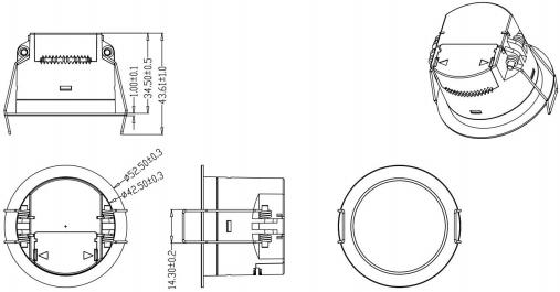
IV. Dimensional Diagram(Units: mm)
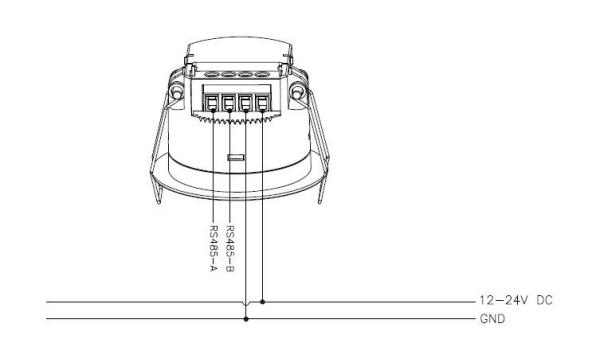
V. Wiring Diagram
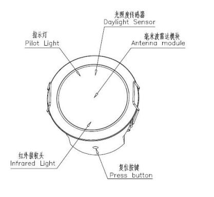
VI. Functional Schematic Diagram
7. Installation Diagram
- Embedded Installation
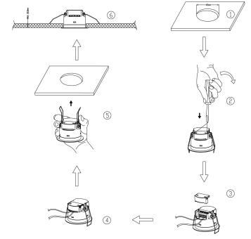
| 1. Ceiling (45mm opening). |
2. Ceiling installation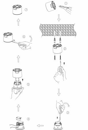
| 1. Use tools to cut off the reserved thin wall of the wire. |
8, Detection distance map
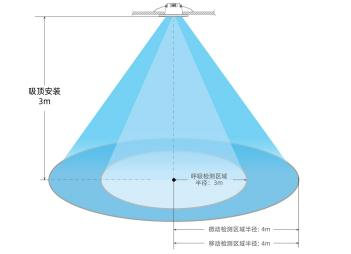
| Remark |
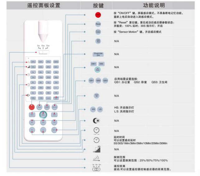
9, Remote control setting method
10, Communication parameter format and protocol
| The baud rate of serial communication | 9600 |
| data bit | 8 |
| stop bit | 1 |
| DATA0 | frame header |
| DATA1 | ID high position |
| DATA2 | Low position ID |
| DATA3 | Length |
| DATA4 | Function |
| DATA5/DATA6/DATA7 | If there is no DATA7, DATA6 is the checksum; If there is no DATA8, DATA7 is the checksum |
| DATA8 | checksum |
| communication data type | HEX format sending and receiving |
| communication data requirements | Each command interval should be greater than 200ms, and the return data should be monitored to see if it is the same as the sending. If it is not received, it should be resent no more than 3 times; |
| frame header | ID high position | Low position ID | Length | Function | Numerical | checksum | |
| DATA0 | DATA1 | DATA2 | DATA3 | DATA4 | DATA5 | DATA6 | |
| 51 | FF | FF | 06 | 05 | 64 | BE |
Checksum: 51+FF+FF+06+05+64=2BE Take the last two digits BE
| Example 2 | frame header | ID High Bit | ID Low Bit | Length | Function | Value | Checksum | ||
| DATA0 | DATA1 | DATA2 | DATA3 | DATA4 | DATA5 | DATA6 | DATA7 | DATA8 | |
| 51 | FF | FF | 08 | 07 | 09 | 27 | C0 | 4E | |
Checksum: 51+FF+FF+08+07+09+27+C0=34E, take the last two 4E digits
| DATA3 Command | Function | Name | data range | read and write | default value |
| 0x00 | Read Function Data | Read Function data | w | ||
| 0x03 | Working Status | Work state | 1-3 | w/r | 01 |
| 0x05 | Sensing Range | Detection area | 0-100 | w/r | 100% |
| 0x08 | LED Indication | LED Indicator | 0-1 | w/r | 01 |
| 0x09 | Illuminance Value | Light sensor | 0-1200 lux | r | |
| 0x0A | Illuminance difference | Difference Value | 10-100 | w/r | 10Lux |
| 0x0D | Delay time | Hold Time | 2-7200 | w/r | 30s |
| 0x17 | Firmware version | Firmware version | 0.0.0-100.0.0 | r | 0.0.1 |
| 0x18 | Device Address | Device ID | 0x0000-0xFF | w/r | 0xFFFF |
| 0x20 | Illuminance multiplier value | Daylight Level Compensation (multiple) | 0x0a-0x64 | w/r | 0x0a |
| 0x21 | EditID | Edit ID | 0- 1 | - | 0x00 |
| 0x22 | Report/Query Switch | Submit a report/Enquire about | 0-1 | w/r | 01 |
| Read Function Data:Read Function data . This function is generally used to query sensor parameters and will return corresponding function data according to the function command number. | ||||||
| Data Example | HEAD (DATA0) | ID (DATA1-DAT A2) | LEN (DATA3) | Function (DATA4) | Value (DATA5) | CRC (DATA6) |
| Query Work Status | 0x51 | 0xFF | 0x06 | 0x00 | 0x03 | data0+...+data5 |
| Query sensing range | 0x51 | 0xFF | 0x06 | 0x00 | 0x05 | data0+...+data5 |
| Query LED status | 0x51 | 0xFF | 0x06 | 0x00 | 0x08 | data0+...+data5 |
| Query the illuminance value | 0x51 | 0xFFFF | 0x06 | 0x00 | 0x09 | data0+...+data5 |
| Query the difference in illuminance | 0x51 | 0xFFFF | 0x06 | 0x00 | 0x0A | data0+...+data5 |
| Query Delay Time | 0x51 | 0xFF | 0x06 | 0x00 | 0x0D | data0+...+data5 |
| Query firmware version | 0x51 | 0xFF | 0x06 | 0x00 | 0x17 | data0+...+data5 |
| Query device address | 0x51 | 0xFF | 0x06 | 0x00 | 0x18 | data0+...+data5 |
| Query whether to allow active reporting | 0x51 | 0xFF | 0x06 | 0x00 | 0x22 | data0+...+data5 |
| 1.Working status:Work state , this function automatically reports the working status of the sensor | ||||||
| sample data | HEAD (DATA0) | ID (DATA1-DAT A2) | LEN (DATA3) | Function (DATA4) | Value (DATA5) | CRC (DATA6) |
| Unmanned state | 0x51 | 0xFFFF | 0x06 | 0x03 | 0x01 | data0+...+data5 |
| Someone's status | 0x51 | 0xFFFF | 0x06 | 0x03 | 0x02 | data0+...+data5 |
| abnormal status | 0x51 | 0xFFFF | 0x06 | 0x03 | 0x03 | data0+...+data5 |
Status reporting instructions:
| 2. Sensing range: This function can set the detection range of the sensor and adjust the corresponding gear according to the size of the space | ||||||
| sample data | HEAD (DATA0) | ID (DATA1-DAT A2) | LEN (DATA3) | Function (DATA4) | Value (DATA5) | CRC (DATA6) |
| Min: 0% | 0x51 | 0xFFFF | 0x06 | 0x05 | 0x00 | data0+...+data5 |
| Max:100% | 0x51 | 0xFFFF | 0x06 | 0x05 | 0x64 | data0+...+data5 |
| 3. LED Indicator light:LED Indicator , this function can setLED indicator light to turn on or off | ||||||
| Data example | HEAD (DATA0) | ID (DATA1-DAT A2) | LEN (DATA3) | Function (DATA4) | Value (DATA5) | CRC (DATA6) |
| Disable | 0x51 | 0xFFFF | 0x06 | 0x08 | 0x00 | data0+...+data5 |
| Enable | 0x51 | 0xFFFF | 0x06 | 0x08 | 0x01 | data0+...+data5 |
| 4.Illuminance value:Light Sensor, this function can obtain the current ambient illuminance value, and when the change in ambient illuminance meets the preset illuminance difference, the sensor immediately reports the ambient illuminance value. | ||||||
| Data Example | HEAD (DATA0) | ID (DATA1-DAT A2) | LEN (DATA3) | Function (DATA4) | Value (DATA5- DATA6) | CRC (DATA7) |
| Min: 0Lux | 0x51 | 0xFFFF | 0x07 | 0x09 | 0x0000 | data0+...+data6 |
| Max: 1200Lux | 0x51 | 0xFFFF | 0x07 | 0x09 | 0x04B0 | data0+...+data6 |
| 5. Light sensitivity difference:Difference Value , the set value of the change in ambient light intensity value, (i.e. reporting the light intensity value immediately when the change in ambient light intensity value exceeds the set value) | ||||||
| Data example | HEAD (DATA0) | ID (DATA1-DA TA2) | LEN (DATA3) | Function (DATA4) | Value (DATA5) | CRC (DATA6) |
| Min: 10Lux | 0x51 | 0xFFFF | 0x06 | 0x0A | 0x0A | data0+...+data5 |
| Max: 100Lux | 0x51 | 0xFFFF | 0x06 | 0x0A | 0x64 | data0+...+data5 |
| 6. Delay time:Hold time This function can set a delay time, which is the delay time for turning on the light after the sensor is triggered. Suggested setting of application time30S to3min | ||||||
| data example | HEAD (DATA0) | ID (DATA1-DA TA2) | LEN (DATA3) | Function (DATA4) | Value (DATA5-D ATA6) | CRC (DATA7) |
| Min: 2s | 0x51 | 0xFFFF | 0x07 | 0x0D | 0x0002 | data0+...+data6 |
| Max: 7200s | 0x51 | 0xFFFF | 0x07 | 0x0D | 0x1C20 | data0+...+data6 |
Note: The delay time needs to be set to at least 30 seconds for the detection function to exist! Within 30 seconds, only motion sensing function is available.
| 7.Firmware version:Firmware version , this feature allows you to view the sensor firmware version number. | ||||||
| Data Example | HEAD (DATA0) | ID (DATA1-DA TA2) | LEN (DATA3) | Function (DATA4) | Value (DATA5-D ATA6) | CRC (DATA7) |
| Min: v0.0.0 | 0x51 | 0xFFFF | 0x07 | 0x17 | 0x0000 | data0+...+data6 |
| Max: v100.0.0 | 0x51 | 0xFFFF | 0x07 | 0x17 | 0x2710 | data0+...+data6 |
| 8.EquipmentID: Device ID , This function can set the deviceID address to distinguish sensor devices with uniqueID. | ||||||
| data example numerical functions | HEAD (DATA0) | ID (DATA1-DA TA2) | LEN (DATA3) | Function (DATA4) | Value (DATA5-D ATA6) | CRC (DATA7) |
| Min: 0x0000 | 0x51 | 0xFFFF | 0x07 | 0x18 | 0x0000 | data0+...+data6 |
| Max: 0xFFFF | 0x51 | 0xFFFF | 0x07 | 0x18 | 0xFFFF | data0+...+data6 |
ID Method: After 20 seconds of power on self-test, press the button briefly once to enter the ID programming mode (51 FF FF 06 21 01 77 appears on the serial port). The indicator light will flash rapidly, and the ID can be set within one minute. After success, the indicator light will stop flashing. (After entering, press the button briefly again to exit the programming mode, and the indicator light will stop flashing)ID Default0xFFFF3) Method for restoring factory settings: Long press the panel button for 3 seconds to restore the factory settings. The device ID will not be restored, and active reporting and passive querying will not be restored.
| 9.Light sensitivity compensation coefficient: Set the multiple of the light sensitivity value to verify the light sensitivity value! | ||||||
| sample data | HEAD (DATA0) | ID (DATA1-D ATA2) | LEN (DATA3) | Function (DATA4) | Value (DATA5-DAT A6) | CRC (DATA7) |
| Min: 0x01 | 0x51 | 0xFFFF | 0x06 | 0x20 | 0x01 | data0+...+data5 |
| Max: 0x64 | 0x51 | 0xFFFF | 0x06 | 0x20 | 0x64 | data0+...+data5 |
| 10. ID Edit status: Used to check ifID allows editing.0: Cannot be changed,1: Can be changed | ||||||
| Data Example | HEAD (DATA0) | ID (DATA1-DA TA2) | LEN (DATA3) | Function (DATA4) | Value (DATA5) | CRC (DATA6) |
| Disable | 0x51 | 0xFFFF | 0x06 | 0x21 | 0x00 | data0+...+data5 |
| Enable | 0x51 | 0xFFFF | 0x06 | 0x21 | 0x01 | data0+...+data5 |
| 11.Report/Query Switch: Used to set whether to actively report.00: Query Mode01: Proactively Reporting | ||||||
| Data Example | HEAD (DATA0) | ID (DATA1-DA TA2) | LEN (DATA3) | Function (DATA4) | Value (DATA5) | CRC (DATA6) |
| Disable | 0x51 | 0xFFFF | 0x06 | 0x22 | 0x00 | data0+...+data5 |
| Enable | 0x51 | 0xFFFF | 0x06 | 0x22 | 0x01 | data0+...+data5 |
Note:
- If there is an error in setting the data range, return: 51XXXX06FF02XX
- If there is no such function or the command is sent incorrectly, there will be no feedback
Eleventh, Initialization Status
The initial power on indicator light flashes for 20 seconds before turning off. During initialization, no external movement sensing signals are detected. The indicator light can be turned off and on through a serial protocol, and the detection range (sensing distance) can be set through a serial protocol.
12, Factory settings
Detection Area:100% Hold Time:1min Indicator light: open
13, Product application precautions:
- Sensors should be installed and wired by professional electricians.
- Sensors should be kept away from large areas of metal plates, glass, and other materials with high dielectric density to avoid triggering errors.
- Avoid using objects that vibrate for a long time around the sensor, such as shaking fans, as the vibration signal will be considered as a movement signal triggering the sensor.
- Avoid ineffective light sources illuminating the detection window of the illuminance sensor of the detector, which may interfere with the measurement of ambient light. When installing and using the product, it should not be too close to the wireless router, at least 2 meters apart.
- When installing and using the product, it should not be too close to the wireless router, at least 2 meters apart.
- Sensitivity and indicator light switch settings can be set using the MH10 remote control, (HS button indicator light "on" LS button indicator light "off" on the remote control)
- Microwave sensors have a certain penetration ability through building walls, and when microwaves penetrate outside the walls and act on moving objects outside the fortified area, they may cause false alarms. To avoid accidental triggering, attention should be paid to selecting the installation location and appropriate sensing range during installation, such as:
- When the product is applied in rooms with a length and width of about 2 meters or less, the sensitivity should be set to 25% (application scenario: bathroom, reception room)
- When applied in a room with a length and width of about 3 meters, the sensitivity should be set to 50%; (Application scenario: restroom entrance and reception room) C. When applied in a room with a length and width of about 4 meters, the sensitivity should be set to 75%; (Application scenario: Small office, conference room, library)
- When applied to rooms with a length and width of about 5 meters or larger, the sensitivity should be set to 100%; (Application scenario: Large office, conference room, library)
Note: The specific sensing range for practical applications depends on the actual environment, and a suitable gear should be set. The sensitivity selection settings for the above application scenarios are only for reference.).
- Delay setting: Single person space: 1-3 minutes, multiplayer space: 30-1 minutes. It is not recommended to set a delay of more than 5 minutes to avoid interference from small motion signals in the space and delay the shutdown time.
- This product does not come with terminal resistors. Please pay attention to impedance matching when connecting to the bus system.