
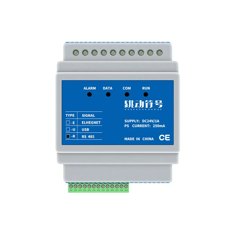
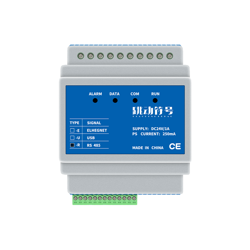
Product Features:
One Product feature introduction:
1.Having a digitally addressable bus control output that can be managed 64 Address devices;
2.Contains three algorithms for allocating addresses, which comply with IEC62386 And GBT30104 Standard automatic address allocation requirements;
3.Capable of broadcasting, group or single address control operations on devices;
4.Can set/read parameters from the standard parameter table;
5.Can achieve group setting/reading;
6.Can achieve scene value setting/reading;
7.Equipped with an independent bus supply power output interface, the compatibility is more flexible;
8.RS485 The interface has photoelectric isolation and lightning protection;
9.Provide open protocols for direct integration with existing control systems, Support configuration software, HMI, PLC Equipment directly Modbus-rtu Docking control;
10.Provide a one week timer function with a built-in high-precision clock, Offline timed control is available;
11Provide four timing table control functions, Each table can be pre installed 32 Change information for each item.
12.support 35mm Rail mounted installation.
Main technical indicators:
Input voltage:DC24V/2A;
power waste:.<=10WV
DALIPower output: 250mA
Ethernet interface: 10M/100MAdaptive, Support 5TCPSimultaneous access of terminals.
Working temperature:-20°C~75°C
Relative humidity:10-90%
Weight:100g
Operating instructions
The gateway has 4 An indicator light is used to indicate the working status of the gateway
COM:express RS485 Communication interface status, Red light indicates gateway reception, Green light indicates gateway transmission;
DATA: Indicate the communication status of the digital addressable interface, Red light indicates data reception, Green light indicates data transmission;
RUN: Indicate the working status of the gateway, Normal operation, To 1 Second frequency flicker;
ALRAM: Bright indicates overcurrent/short circuit protection for the output bus supply power supply.
Definition of communication transmission methods:
Communication transmission method ---Compatibility Modbus RTU Regulations (Please refer to Modbus Starting from the protocol frame Definition of beginning and end, And related regulations)
The parameters in red below are factory settings, You can choose to make changes
data bit:8 bit
Parity check bit: (None) ,Odd verification, Occasional verification
Stop position:2 bit, 1bit
Baud rate: 1200;2400;4800;9600;14400;19200;38400;
Factory default: 9600,8,N,2
Frame structure definition:
Address code Function code Data area CRC Verification code
1 Byte 1Byte NByte 2Byte
Address code: The address code is the first byte of communication transmission. This byte indicates that the slave set by the user will receive the address codeMODBUSInformation sent by the host.
And each slave has a unique address code, And the response feedback starts with their respective address codes.
The address code sent by the host indicates the address of the slave to be sent, The address code sent by the slave indicates the address of the slave being sent back.
Function code: The second byte of communication transmission, Send as a host request, Notify the slave through the function code
What action to perform. As a slave response, The function code sent from the slave is the same as the function code sent from the master, And it indicates that the slave has responded to the host for operation, and this device only responds to power codes:0x03,0x06,0x10.
Data area: The data area varies according to different function codes. The data area can be parameters, Parameter length, etc, The specific content of the data area is determined by the function code.
CRC Verification code: Two byte CRC16 Detection code, Low byte first, High byte after.
Response from the machine:
Response address: Only respond to local address, broadcast address(0x00)Will not respond, but will be executed when writing operations;
Response time: According to the number of registers read/write, the response time varies
The more devices there are, the longer the response time. The response time of this gateway is 3 Within seconds.
Function code description:
The function codes that this device responds to are::0x03,0x06,0x10.
Please refer to the "Technical Development Document" provided by our company for a detailed introduction.
Dial code setting, address setting:
There is one next to the plug and unplug terminal of the gateway device 8 The dip switch for the position is used to set the gateway address(Modbus Station number)
As shown in the figure on the right, This device uses one 8 Set the address for the dip switch of the position, Set the range of addresses:
0~255, This device supports 0 Address as broadcast address.
Each dip switch position corresponds to a numerical value, Switch direction ON Indicating validity, Turn towards ON
Sum up the numerical values of bits, It is the address of this device.
Dial switch position number 1 2 3 4 5 6 7 8
Numerical value 1 2 4 8 16 32 64 128
Like: Dial switch 1, 2, 4 Positioning direction ON, The address of this device is:: 1+2+8=11The set value is:
0: Broadcast address;
1~247: Equipment single address;
255: Power on again 5 The baud rate will be restored to its factory default value in seconds 9600,8,N,2 .
Other values are retained.
Test control terminals:
For the convenience of not connecting to the higher-level system after installation, Test whether the circuit is correct, IN1,IN2
To install the testing end, The specific operation method is::
INT1 yes GND
Short press: Turn on the lights, All lights are controlled simultaneously;
Long press: raise, All lights are controlled simultaneously;
INT2 yes GND
Short press: Turn off the lights, All lights are controlled simultaneously;
Long press: Downward adjustment, All lights are controlled simultaneously;
Fire linkage terminal:
LF+,LF-Two are fire voltage(DC12~36V)Input terminal, usually when the fire signal is valid, All
Turn on the lights to maximum brightness. Simultaneously supporting self setting, The signal can be set to have voltage or no voltage signal
Effective, Can set the lighting action when the signal is valid.
Product Purchase: https://item.taobao.com/item.htm?ft=t&id=665791085313


Leave a Reply