
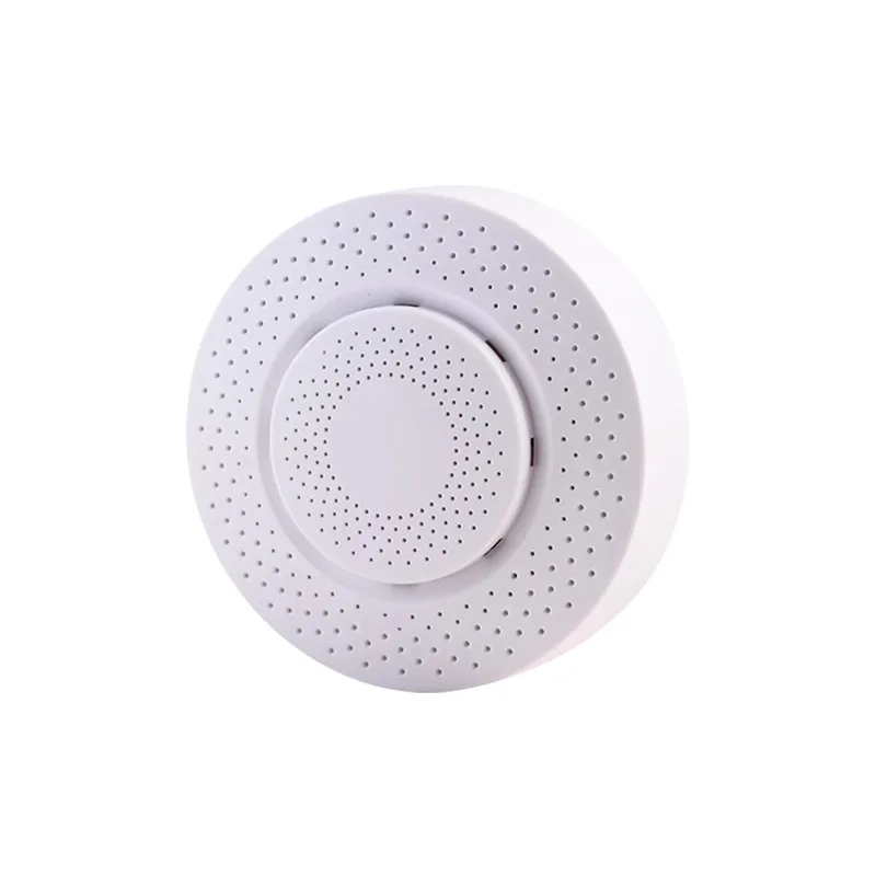
Product Function Description:
③ One register holds 2 bytes of data, while air pressure occupies 4 bytes, making it 2 registers. Therefore, when reading air pressure, it is necessary to read both consecutive registers, and each other sensor data occupies 2 bytes, making it 1 register.
Method 2: If it is greater than 0x7fff (32767)
| 2.1 Detection parameters and resolution | |||
| Sensor data | Measurement resolution | Measurement range | Measurement accuracy |
| carbon dioxide eCO2 | 1ppm | 400 ~ 60,000ppm | ±30ppm |
| TVOC | 1ug/m3 | 0 ~ 60,000ug/m³ | ±50ug/m3 |
| Formaldehyde CH2O | 1ug/m3 | 0 ~ 1,000ug/m³ | ±25% |
| PM2.5 | 1ug/m3 | 0 ~ 1,000ug/m³ | ±10% |
| PM10 | 1ug/m3 | 0 ~ 1,000ug/m³ | ±10% |
| PM1.0 | 1ug/m3 | 0 ~ 1,000ug/m³ | ±10% |
| Temperature | 0.01℃ | -40 ~ 85℃ | ±0.2℃ |
| Humidity | 0.01% | 0 ~ 100% | ±1%RH |
| Air pressure | 1Pa | 30,000 ~ 110,000Pa | ±12Pa |
| Illuminance | 1Lux | 0 ~ 60,000Lux | ±5% |
| Noise | 1dB | 30 ~ 90dB | ±3dB |
Note Module output: The value is CH2O Equivalent value of TVOC Please pay attention when customers purchase and use, Working voltage.
2.2 Work environment: DC5V±0.2V @150mA
2.3 Working temperature: Working humidity- 10 ~ 60℃, No condensation: 5 ~ 95%RH (Communication method)
2.4 Interface: Modbus-RTU 485 Preheating time
2.5 Less than: minute 3 semiconductor
In theory, the longer the sensor is powered on, the more stable it becomes VOC service life
2.6 Year: 3 In the air (Product specifications)
III.Appearance dimension diagram
3.1 Standard
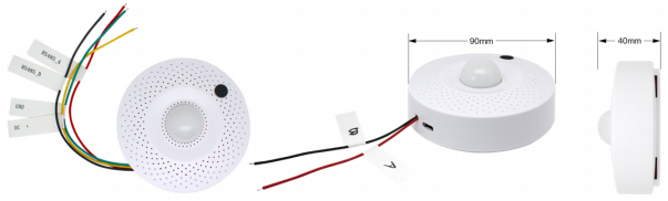
I , Line interface 4 Line II , 2 Power supply interface + USB As shown in the above figure
This product, Supply⃞Standard“Line interface 4 And”Line“2 Power supply+USB Two physical interfaces”When making a purchase, please follow the instructions, Indicate according to actual needs This product is used by default.
DC power supply 5V If special voltage is required, You can contact us for customization (6 - 36V) , Definition of wiring.
3.2 Standard
1) “Line 4 Interface type”Serial number:
| name | Remark | Remark |
| RS485_A | Yellow | RS485_A |
| RS485_B | Green | RS485_B |
| DC+ | red Default | DC power supply 5V Special voltage needs to be customized, Black |
| GND | ground wire | Line |
2) “2 Power supply+USB Interface type”Serial number:
| name | Describe | ⃞red Black |
| A | direct (A) | RS485_A |
| B | Power supply (B) | RS485_B |
| U | Micro USB | Note The colors in the table above are general descriptions 5V Please refer to the label on the product for specific wiring instructions |
Communication protocol: Communication parameters, Parameters.
IV.RS485 Factory default address
4.1 Return data time
ModBus-RTU 485 Less than: 9600/8/N/1
Communication protocol: 0x01
Read address command: Direction 100ms
4.2 User applications
1) Sensor module
Need to respond: Yes->Request message format; Byte number: data explain
Broadcast address:
| Report the slave address function code | Fixed | Fixed |
| 0 | 0xFE | Fixed |
| 1 | 0x11 | Fixed |
| 2 | 0x00 | Verification |
| 3 | 0x00 | Response message format |
| 4 | 0x00 | Byte number |
| 5 | 0x01 | data explain |
| 67 | CRC_LCRC_H | CRC Slave address |
Report the slave address function code:
| Byte count | Firmware version | Current address |
| 0 | 0x01 | Verification |
| 1 | 0x11 | For example |
| 2 | 0x02 | Send commands |
| 3 | version | Return data |
| 4 | address | explain |
| 56 | CRC_LCRC_H | CRC Return data |
for example: send command: FE 11 00 00 00 01 28 06
return data: 01 11 02 12 01 70 5C
Instructions: Return data 0x12 The version number is represented as V1.2 , 0x01 Indicates that the device address is 01
2) Modify address command. The default factory address for the module is 0x01, The address range can be changed to: 1~247
Direction: User applications->Sensor module; Need to respond: Yes
Request message format:
| Byte number | data explain | Current address |
| 0 | address | Function code |
| 1 | 0x06 | Fixed |
| 2 | 0x00 | Fixed |
| 3 | 0x00 | reserve |
| 4 | 0x00 | New address |
| 5 | new address | Verification |
| 67 | CRC_L CRC_H | CRC Response message format |
Byte number:
| data explain | Address before modification | Function code |
| 0 | address | Fixed |
| 1 | 0x06 | Fixed |
| 2 | 0x00 | reserve |
| 3 | 0x00 | The modified address |
| 4 | 0x00 | Verification |
| 5 | new address | For example |
| 67 | CRC_L CRC_H | CRC The current address is |
The preset address is: Send commands: 0x01 , Return data: 0x02
The current address is from: 01 06 00 00 00 02 08 0B
Change back: 01 06 00 00 00 02 08 0B
Send commands: 0x02 , Return data: 0x01
Read data command: 02 06 00 00 00 01 48 39
Direction: 02 06 00 00 00 01 48 39
3) User applications
Sensor module: Need to respond->Yes; Request message format: Byte number
data explain:
| Current address | Function code | Register start address |
| 0 | address | The number of sensors that need to be read |
| 1 | 0x03 | Verification |
| 2 3 | 0x00 MM | Response message format |
| 4 5 | 0x00 NN | Byte number |
| 6 7 | CRC_L CRC_H | CRC data Instructions |
Response message format:
| Byte number | data | Instructions |
| 0 | address | Current address |
| 1 | 0x03 | Function code |
| 2 | NN*2 | Data length |
| 3 | xx xx...... | Sensor data (Air pressure ratio 4 Byte, Both 2 A register; The data from each other sensor accounts for 2 Byte, Both 1 A mailing Memory) |
| 3+NN*2 4+NN*2 | CRC_L CRC_H | CRC Verification |
Note The return sensor data can be changed according to the register address and data length: Register address.
The corresponding sensor data is explained as follows (0x00MM) Air pressure ratio, Byte 4 A register (2 Each other transmission) , Sensor data occupancy Byte 2 A register (1 Register address) .
| Sensor data | Number of occupied registers | Humidity |
| 0x0000 | eCO2 | 1 |
| 0x0001 | TVOC | 1 |
| 0x0002 | CH2O | 1 |
| 0x0003 | PM2.5 | 1 |
| 0x0004 | Temperature | 1 |
| 0x0005 | Illuminance | 1 |
| 0x0006 | PM10 | 1 |
| 0x0007 | PM1.0 | 1 |
| 0x0008 | Temperature (Lux) | 1 |
| 0x0009 | MCU Noise | 1 |
| 0x000A | Air pressure (dB) | 1 |
| 0x000B | explain (Pa) | 2 |
Number of sensors:
① The minimum is 00 NN The maximum is 00 01, The value is 00 0B. MM Time 00 The maximum value can be, NN Can read at this time 0B, Provide the values of all sensors For, NN It can only be read separately 01 The data eCO2 For, NN Can be read at any time 02 And eCO2 The number TVOC According to
and so on, The address at the beginning of the register.
② When increasing the length of data, Can read data from subsequent sensors, But the address at the back of the register, no Can read data from sensors prior to this address, One register can hold it Byte data.
③ One register can accommodate 2 Byte data, Air pressure ratio 4 Byte, Both 2 A register, Therefore, When reading the air pressure, continuous readings should be taken Read both registers, The data from each other sensor accounts for 2 Byte, Both 1 A register.
The details are as follows::
| 00MM00NN | Readable data |
| 00000001 | Indicate from the starting address 0000 Read CO2 data Indicate from the starting address |
| 00000002 | Read 0000 data Indicate from the starting address CO2 , TVOC Read |
| ...... | ...... |
| 0000000D | Wet 0000 Degree CO2, TVOC, CH2O, PM2.5, Temperature Illuminance, Temperature, PM10, PM1.0, Noise data, MCU Air pressure, data Indicate from the starting address, Read data Indicate from the starting address |
| 00010001 | Read 0001 data Indicate from the starting address TVOC Take |
| 00010002 | Humidity 0001 Temperature TVOC, CH2O Degree |
| ...... | ...... |
| 00010007 | data Indicate from the starting address 0001 Take TVOC, CH2O, PM2.5, Humidity, Temperature Degree, PM10, PM1.0 Illuminance |
| 0001000C | Temperature 0001 Noise data, air pressure data TVOC, CH2O, PM2.5, Indicate from the starting address, Read data Indicate from the starting address, PM10, PM1.0, Read, MCU data Indicate from the starting address, Read air pressure data |
| 00020001 | A register 0002 For example CH2O The address of the module is |
| 00020002 | Indicates starting from the starting address 0002 read CH2O, PM2.5 data |
| ...... | ...... |
| 000B0001 | Indicates starting from the starting address 000B Read air pressure data (2 A register) |
for example: The address of the module is 0x01,
User sent: 01 03 00 00 00 09 85 CC , You can use it 9 Read sensor data;
User sent: 01 03 00 00 00 0B 04 0D , You can use it 11 Sensor data (Including MCU Temperature) Read out;
User sent: 01 03 00 00 00 0D 84 0F , You can use it 12 Sensor data (Air pressure ratio 2 A register) Read out;
User sent: 01 03 00 0B 00 02 B5 C9 , Only reading air pressure data (Occupy 2 A register) .
4) Read a frame of data
5) The returned data format is as follows::
| Byte number | data explain | Message header |
| 0 | 0x01 | Function code |
| 1 | 0x03 | Data length |
| 2 | 0x1A | data data data data Humidity data |
| 3 4 | CO2_H CO2_L | CO2 Temperature data |
| 5 6 | TVOC_H TVOC_L | TVOC data data Illuminance |
| 7 8 | CH2O_H CH2O_L | CH2O data Temperature data |
| 9 10 | PM2.5_H PM2.5 L | PM2.5 Noise |
| 11 12 | Humi_H Humi_L | data Air pressure data |
| 13 14 | Temp_H Temp_L | Verification |
| 15 16 | PM10_H PM10_L | PM10 System parameter configuration |
| 17 18 | PM01_H PM01_L | PM1.0 You can read the register addresses in the table below |
| 19 20 | Lux_H Lux_L | Write (Lux) To obtain or modify system parameters |
| 21 22 | MCU_TEMP_H MCU_TEMP_L | MCU Note This is an advanced feature |
| 23 24 | dB_H dB_L | Please use with caution (dB) To avoid causing system parameter errors |
| 25 26 27 28 | Pa_byte[3] Pa_byte[2] Pa_byte[1] Pa_byte[0] | Affects sensor functionality or data accuracy (Pa) |
| 29 30 | CRC16_L CRC16_H | CRC16 Register address |
6) Length
7) Byte, System parameters, Sensor configuration bitmap.
8) Byte: before, Is it an external temperature and humidity sensor, byte, Affects sensor functionality or data accuracy.
| register address | Length (byte) | system parameters |
| 0x0100 | 4 | Sensor configuration bitmap (Sensor Map) |
| 0x0110 | 2 | byte 1 (ahead) : Is it an external temperature and humidity sensor byte 2: Sensor data user calibration bitmap, Refer to“Sensing Device module bitmap ” |
| 0x0111 | 2 | Byte 1 (before) : The sensor number corresponding to the custom indicator item of the dedicated serial port screen Byte 2: Light transmittance of the photosensitive cover of the illuminance sensor (0- 100) , 0 Indicating the absence of a photosensitive mask, 100 Indicating no loss |
| 0x0118 | 2 | CO2 Calibration value, int16 |
| 0x0119 | 2 | TVOC Calibration value, int16 |
| 0x011A | 2 | CH2O Calibration value, int16 |
| 0x011B | 2 | PM2.5 Calibration value, int16 |
| 0x011C | 2 | Humidity calibration value (100 Double) , int16 |
| 0x011D | 2 | Temperature calibration value (100 Double) , int16 |
| 0x011E | 2 | PM10 Calibration value, int16 |
| 0x011F | 2 | PM1.0 Calibration value, int16 |
| 0x0120 | 2 | Illuminance (Lux) Calibration value, int16 |
| 0x0121 | 2 | MCU Temperature calibration value, int16 |
| 0x0122 | 2 | Noise (dB) Calibration value, int16 |
| 0x0123 | 2 | Atmospheric pressure calibration value, int16 |
Note All user calibration values are signed integers:
1.Negative numbers indicate negative offset, We need to subtract the offset, The user calibration values for temperature/humidity are amplified in degrees Celsius;
2.Double 100 Like, Indicates the need to add: 250 centigrade 2.5 Expressing a need; -110 subtract centigrade 1.1 For example.
The address of the module is: User sent 0x01,
Read the external temperature and humidity sensor label and sensor data user calibration bitmap: 01 03 01 10 00 01 84 33 , User sent; Turn on the temperature and humidity user calibration switch: 01 06 01 10 00 02 04 0D , User sent;
Read the temperature and humidity calibration values: 01 03 01 1D 00 01 15 F0 , User sent;
Set temperature user calibration values: 01 06 01 1D 00 FA 98 73 , Both 250, Degree+2.5 User sent; Set temperature user calibration values: 01 06 01 1D 80 6E F8 1C , Both-110, Degree-1.1 Computer reading.
4.3 data Through RS485 Convert to serial port
adapter“485 Convert to serial port”adapter, The sensor module can be connected to a computer to detect communication and view data. The computer can enable Use ModBus Testing tools (Like: ShortBus Modbus Scanner, The effect is shown in the following figure) Directly read data; It can also be used“String Oral assistant”Waiting for standard serial port tools, Obtain data by sending query messages.
V. Various sensor data calculation methods
. CO2 (ppm) = CO2_H * 256 + CO2_L
. TVOC (ug/m3) = TVOC_H * 256 + TVOC_L
. CH2O (ug/m3) = CH2O_H * 256 + CH2O_L
. PM2.5 (ug/m3) = PM2.5_H * 256 + PM2.5_L
. PM10 (ug/m3) = PM10_H * 256 + PM10_L
. PM1.0 (ug/m3) = PM01_H * 256 + PM01_L
. Illumination (Lux) = Lux_H * 256 + Lux_L
. Noise (dB) = dB_H * 256 + dB_L
. The temperature returned by the interface, Humidity (Real data 100 Double) :
. Positive temperature (℃) = (Temperature_H * 256 + Temperature_L) / 100, For example: T = (0x09d0) / 10 = 2512 / 100 = 25.12℃
. Negative temperature (℃)
method 1: Directly convert to signed int Type is sufficient, For example: T = 0xfc83/10 = -893/100 = -8.93℃
method 2: If greater than 0x7fff (32767)
Then it is a negative number T = (0xfc83 - 65536) / 10 = (64643 - 65536) / 10 = -893 / 100 = -8.93℃
. Humidity (%RH) = (Humidity_H * 256 + Humidity_L) / 100
. Air pressure (Pa) = Pa_byte[3] * 224 + Pa_byte[2] * 216 + Pa_byte[1] * 28 + Pa_byte[0]
. Calculate altitude based on air pressure
The unit of air pressure is Pa, theoretically, Every increase in altitude 9 Rice, Atmospheric pressure decreases 100 Pa. And the standard atmospheric pressure at sea level is 101,325 Pa, Therefore, You can use the following formula based on the air pressure value(Pa)Calculate altitude(Altitude)Approximate value of:
1 , Simplified altitude formula = (101325 – Pa) / 100 * 9
Apart from altitude, There are many factors that can affect air pressure (For example, temperature) , The following formula is relatively more accurate, Especially in the high seas Pull position:
2 , Calibration version altitude formula = 44330 * (1 – (Pa/101325)0.1903)
For example: If the measured air pressure value is 99,882Pa, The altitude calculated by the two formulas(Altitude)They are respectively::
. Simplified version of altitude = (101325 – 99882) / 100 * 9 = 129.8 Rice
. Calibration version altitude = 44330 * (1 – (99882/101325)0.1903) = 120.84 Rice
VI.matters needing attention
. Preheating is required for initial power on use 3 More than minutes
. The installation position of the sensor should be higher than the ground 15~20CM above, Otherwise, there may be ground dust and sand, Large dust particles such as floating debris or even flocs The contamination of the object causes the fan to become entangled and stall, It is recommended to adopt appropriate pre filtering treatment for the equipment.
. This product is a precision instrument, Please do not open the casing, Normal operation does not require knowledge of the internal conditions of the equipment. If the equipment is damaged, must Maintenance and repair by professional personnel, Please confirm that the external power supply has been disconnected before maintenance and repair. .
. Sensor data ensures consistency between individual products at the factory, Do not use third-party testing instruments or data as comparison standards. If the user wishes Hope the final measurement results are consistent with a third-party testing device, Users can perform data fitting and calibration based on actual collection results.
. This sensor is suitable for ordinary indoor environments, If the user device is used in the following actual environment, Sensors may have excessive accumulation Dust, Oil accumulation, Water ingress leads to a decrease in data consistency. For example: The annual dust concentration is greater than 300 Microgram/cubic meter time exceeds 50% , Or greater than 500 Microgram/cubic meter time exceeds 20%; Oil fume environment; High water mist environment; Outdoor activities, etc.
VII. Sensor module bitmap
| Position | Sensor module |
| 0x01 | Illuminance |
| 0x02 | Temperature, humidity, and air pressure |
| 0x04 | Dust |
| 0x08 | Air quality |
| 0x10 | Noise |
VIII. CRC Verify the calculation method
CRC Code and examples can be referred to: https://github.com/sunbaoshi1975/CRCTool
Function functionality: CRC Verification function, Generate CRC
Parameter description: pushMsg: The array set that needs to be verified
usDataLen : Need to verify the length of the data
Return parameters: CRC For unsigned int16 Type, The high-order byte is before the high-order byte, Low at the back
/*CRC verify high position*/
const unsigned char auchCRCHi[] = {
0x00, 0xC1, 0x81, 0x40, 0x01, 0xC0, 0x80, 0x41, 0x01, 0xC0, 0x80, 0x41, 0x00, 0xC1, 0x81,
0x40, 0x01, 0xC0, 0x80, 0x41, 0x00, 0xC1, 0x81, 0x40, 0x00, 0xC1, 0x81, 0x40, 0x01, 0xC0,
0x80, 0x41, 0x01, 0xC0, 0x80, 0x41, 0x00, 0xC1, 0x81, 0x40, 0x00, 0xC1, 0x81, 0x40, 0x01,
0xC0, 0x80, 0x41, 0x00, 0xC1, 0x81, 0x40, 0x01, 0xC0, 0x80, 0x41, 0x01, 0xC0, 0x80, 0x41,
0x00, 0xC1, 0x81, 0x40, 0x01, 0xC0, 0x80, 0x41, 0x00, 0xC1, 0x81, 0x40, 0x00, 0xC1, 0x81,
0x40, 0x01, 0xC0, 0x80, 0x41, 0x00, 0xC1, 0x81, 0x40, 0x01, 0xC0, 0x80, 0x41, 0x01, 0xC0,
0x80, 0x41, 0x00, 0xC1, 0x81, 0x40, 0x00, 0xC1, 0x81, 0x40, 0x01, 0xC0, 0x80, 0x41, 0x01,
0xC0, 0x80, 0x41, 0x00, 0xC1, 0x81, 0x40, 0x01, 0xC0, 0x80, 0x41, 0x00, 0xC1, 0x81, 0x40,
0x00, 0xC1, 0x81, 0x40, 0x01, 0xC0, 0x80, 0x41, 0x01, 0xC0, 0x80, 0x41, 0x00, 0xC1, 0x81,
0x40, 0x00, 0xC1, 0x81, 0x40, 0x01, 0xC0, 0x80, 0x41, 0x00, 0xC1, 0x81, 0x40, 0x01, 0xC0,
0x80, 0x41, 0x01, 0xC0, 0x80, 0x41, 0x00, 0xC1, 0x81, 0x40, 0x00, 0xC1, 0x81, 0x40, 0x01,
0xC0, 0x80, 0x41, 0x01, 0xC0, 0x80, 0x41, 0x00, 0xC1, 0x81, 0x40, 0x01, 0xC0, 0x80, 0x41,
0x00, 0xC1, 0x81, 0x40, 0x00, 0xC1, 0x81, 0x40, 0x01, 0xC0, 0x80, 0x41, 0x00, 0xC1, 0x81,
0x40, 0x01, 0xC0, 0x80, 0x41, 0x01, 0xC0, 0x80, 0x41, 0x00, 0xC1, 0x81, 0x40, 0x01, 0xC0,
0x80, 0x41, 0x00, 0xC1, 0x81, 0x40, 0x00, 0xC1, 0x81, 0x40, 0x01, 0xC0, 0x80, 0x41, 0x01,
0xC0, 0x80, 0x41, 0x00, 0xC1, 0x81, 0x40, 0x00, 0xC1, 0x81, 0x40, 0x01, 0xC0, 0x80, 0x41,
0x00, 0xC1, 0x81, 0x40, 0x01, 0xC0, 0x80, 0x41, 0x01, 0xC0, 0x80, 0x41, 0x00, 0xC1, 0x81, 0x40 };
/* CRC verify low position*/
const unsigned char auchCRCLo[] = {
0x00, 0xC0, 0xC1, 0x01, 0xC3, 0x03, 0x02, 0xC2, 0xC6, 0x06, 0x07, 0xC7, 0x05, 0xC5, 0xC4,
0x04, 0xCC, 0x0C, 0x0D, 0xCD, 0x0F, 0xCF, 0xCE, 0x0E, 0x0A, 0xCA, 0xCB, 0x0B, 0xC9, 0x09,
0x08, 0xC8, 0xD8, 0x18, 0x19, 0xD9, 0x1B, 0xDB, 0xDA, 0x1A, 0x1E, 0xDE, 0xDF, 0x1F, 0xDD,
0x1D, 0x1C, 0xDC, 0x14, 0xD4, 0xD5, 0x15, 0xD7, 0x17, 0x16, 0xD6, 0xD2, 0x12, 0x13, 0xD3,
0x11, 0xD1, 0xD0, 0x10, 0xF0, 0x30, 0x31, 0xF1, 0x33, 0xF3, 0xF2, 0x32, 0x36, 0xF6, 0xF7,
0x37, 0xF5, 0x35, 0x34, 0xF4, 0x3C, 0xFC, 0xFD, 0x3D, 0xFF, 0x3F, 0x3E, 0xFE, 0xFA, 0x3A,
0x3B, 0xFB, 0x39, 0xF9, 0xF8, 0x38, 0x28, 0xE8, 0xE9, 0x29, 0xEB, 0x2B, 0x2A, 0xEA, 0xEE,
0x2E, 0x2F, 0xEF, 0x2D, 0xED, 0xEC, 0x2C, 0xE4, 0x24, 0x25, 0xE5, 0x27, 0xE7, 0xE6, 0x26,
0x22, 0xE2, 0xE3, 0x23, 0xE1, 0x21, 0x20, 0xE0, 0xA0, 0x60, 0x61, 0xA1, 0x63, 0xA3, 0xA2,
0x62, 0x66, 0xA6, 0xA7, 0x67, 0xA5, 0x65, 0x64, 0xA4, 0x6C, 0xAC, 0xAD, 0x6D, 0xAF, 0x6F,
0x6E, 0xAE, 0xAA, 0x6A, 0x6B, 0xAB, 0x69, 0xA9, 0xA8, 0x68, 0x78, 0xB8, 0xB9, 0x79, 0xBB,
0x7B, 0x7A, 0xBA, 0xBE, 0x7E, 0x7F, 0xBF, 0x7D, 0xBD, 0xBC, 0x7C, 0xB4, 0x74, 0x75, 0xB5,
0x77, 0xB7, 0xB6, 0x76, 0x72, 0xB2, 0xB3, 0x73, 0xB1, 0x71, 0x70, 0xB0, 0x50, 0x90, 0x91,
0x51, 0x93, 0x53, 0x52, 0x92, 0x96, 0x56, 0x57, 0x97, 0x55, 0x95, 0x94, 0x54, 0x9C, 0x5C,
0x5D, 0x9D, 0x5F, 0x9F, 0x9E, 0x5E, 0x5A, 0x9A, 0x9B, 0x5B, 0x99, 0x59, 0x58, 0x98, 0x88,
0x48, 0x49, 0x89, 0x4B, 0x8B, 0x8A, 0x4A, 0x4E, 0x8E, 0x8F, 0x4F, 0x8D, 0x4D, 0x4C, 0x8C,
0x44, 0x84, 0x85, 0x45, 0x87, 0x47, 0x46, 0x86, 0x82, 0x42, 0x43, 0x83, 0x41, 0x81, 0x80, 0x40 };
/*CRC check*/
uint16_t CRC16_Check(const uint8_t *pushMsg, uint8_t usDataLen)
{
 uint8_t uchCRCHi = 0xff;//high CRC init
 uint8_t uchCRCLo = 0xff;//low CRC init
 uint8_t uIndex; //CRC index in loop
while(usDataLen--) {
uIndex = uchCRCLo^ *pushMsg++;//cal CRC
uchCRCLo = uchCRCHi^ auchCRCHi[uIndex];
uchCRCHi = auchCRCLo[uIndex];
}
return((uint16_t)uchCRCHi << 8 | uchCRCLo);
}

Leave a Reply