
Description
Product Overview
This series of IPDU intelligent instrument products is suitable for single-phase and three-phase systems and is one of the key components of the electric meter cabinet distribution unit (PDU). After installation on the PDU body, the device not only provides active metering function, but also can issue real-time local and remote alarms through the set alarm threshold, effectively reducing operational risks. The power usage data it provides supports data center managers to make informed decisions about load balancing and IT scale rationalization, thereby significantly reducing total cost of ownership.
Feature Introduction
-Electrical parameters: Input voltage is 176-264VAC, single-phase or three-phase; Maximum input current of 63A; output voltage of 176-264VAC; The number of output bits is optional, up to a maximum of 48 bits; Open circuit protection is optional.
Model Selection
-The basic model is IPDU-010063: * * Among them, "IPDU-XXXXXX-XXXX" is the identification of the intelligent instrument PDU, and subsequent numbers and letters represent specific configurations, such as installation method (vertical or horizontal), power type (DC, single-phase, three-phase, etc.), supported control and monitoring functions, etc.
Installation and maintenance
IPDU should be installed at the front end of a 19 inch industrial cabinet to protect the backend equipment. After connecting to the power system, the backend devices can be powered on for operation. During installation, it is important to note that the load current should not exceed 16A and overloading is strictly prohibited. Please use a fixed bracket and connect the wires correctly during installation, and pay attention to electrical safety.
Network operation
PDU can be accessed through a web interface using supported browsers such as Google Chrome or Mozilla Firefox. The default static IP address for PDU is 192.168.0.163, and users can query the current IP address through the network status page of the display module. If dynamic IP configuration is required, the DHCP function of the device needs to be enabled.
Communication Protocol
This instrument adopts the MOBUS-TCP/MODBUS-RTU protocol, and the physical channel uses network port/serial port. The network port is 502, and the default address is 1. Among them, the three-phase type includes all the following data, and the single-phase type header only uses A-phase data.
Byte Characteristics
The network uses the Modbus TCP protocol and is a slave device. The host needs to send request instructions to obtain protocol data content, which comply with the Modbus TCP related framing characteristics.
input register
| Serial number | register address | Name | Meaning Explanation |
| 1 | 0x0000 | Ver | Instrument Version |
| 2 | 0x0001 | Info | PDU information |
| 3 | 0x0002 | Statue | PDU status |
| 4 | 0x0003 | A_Urms | A-phase voltage, unit: 0.1V |
| 5 | 0x0004 | A_Irms_H | A-phase current high, unit: 0.001A |
| 6 | 0x0005 | A_Irms_L | A-phase current low, unit: 0.001A |
| 7 | 0x0006 | A_Active_Power | A-phase active power, unit: 0.001kW |
| 8 | 0x0007 | A_Reactive_Power | A-phase reactive power, unit: 0.001kVar |
| 9 | 0x0008 | A_Apparent_Power | A-phase apparent power, unit: 0.001kVA |
| 10 | 0x0009 | A_Power_Factor | A-phase power factor, unit: 0.001 |
| 11 | 0x000A | A_Active_Energy_H | A-phase active electrical energy, unit: 0.001 kWh |
| 12 | 0x000B | A_Active_Energy_L | |
| 13 | 0x000C | A_Reactive_Energy_H | A Reactive electrical energy, unit: 0.001 kVarh |
| 14 | 0x000D | A_Reactive_Energy_L | |
| 15 | 0x000E | B_Urms | B Phase voltage, unit: 0.1V |
| 16 | 0x000F | B_Irms-H | B-phase current high, unit: 0.001A |
| 17 | 0x0010 | B_Irms_L | B-phase current low, unit: 0.001A |
| 18 | 0x0011 | B_Active-Power | B-phase active power, unit: 0.001kW |
| 19 | 0x0012 | B-Reactive_Power | B-phase reactive power, unit: 0.001kVar |
| 20 | 0x0013 | B_Apparel Power | B-phase apparent power, unit: 0.001kVA |
| 21 | 0x0014 | B_Power Factor | B-phase power factor, unit: 0.001 |
| 22 | 0x0015 | B_Active-Energy H | B-phase active electrical energy, unit: 0.001 kWh |
| 23 | 0x0016 | B_Active_Energy_L | |
| 24 | 0x0017 | B_Reactive_Energy_H | B-phase reactive electrical energy, unit: 0.001 kVarh |
| 25 | 0x0018 | B_Reactive_Energy_L | |
| 26 | 0x0019 | C_Urms | C Phase voltage, unit: 0.1V |
| 27 | 0x001A | C_Irms-H | , high current of phase C, unit: 0.001A |
| 28 | 0x001B | C_Irms_L | , low current of phase C, unit: 0.001A |
| 29 | 0x001C | C_Active-Power | C-phase active power, unit: 0.001kW |
| 30 | 0x001D | C_Reactive Power | C-phase reactive power, unit: 0.001kVar |
| 31 | 0x001E | C_Apparel Power | C-phase apparent power, unit: 0.001kVA |
| 32 | 0x001F | C_Power Factor | C-phase power factor, unit: 0.001 |
| 33 | 0x0020 | C-phase active electrical energy | , unit: 0.001 kWh |
| 34 | 0x0021 | C_Active_Energy_L | |
| 35 | 0x0022 | C_Reactive_Energy_H | C Reactive electrical energy, unit: 0.001 kVarh |
| 36 | 0x0023 | C_Reactive_Energy_L | |
| 37 | 0x0024 | Total_Active_Power | Phase combination, active power, unit 0.001kW |
| 38 | 0x0025 | Total-Reactive-Power | Phase combination, reactive power, unit 0.001kVar |
| 39 | 0x0026 | Total-Apparent-Power | Phase combination, apparent power, unit 0.001kVA |
| 40 | 0x0027 | Total-Power_factor | Phase combination, power factor, unit 0.001 |
| 41 | 0x0028 | Total-Active_Energy_H | Phase combination, active electrical energy, unit: 0.001 kWh |
| 42 | 0x0029 | Total_Active_Energy_L | |
| 43 | 0x002A | Total_Reactive_Energy_H | Phase combination, reactive electrical energy, unit 0.001kVarh |
| 44 | 0x002B | Total-Reactive Energy_L |
| Serial number | Register address | Name | Meaning explanation |
| 45 | 0x002C | Reserve | Reserve |
| 46 | 0x002D | Zero_irms | Zero line current, unit: 0.01A |
| 47 | 0x002E | Reserve | Reserve |
| 48 | 0x002F | Phase-Unbalance | Three phase imbalance, unit: 1% |
| 49 | 0x0030 | Freq | Grid frequency, unit: 0.001HZ |
| 50 | 0x0031 | Temperature__1 | Temperature 1: bit15 represents connection status, bit14~bit12 represents status: 0 not exceeding limit, 1, exceeding upper limit, 2, exceeding lower limit; The lower 12 bits represent temperature, with the unit being 0.1 ℃ |
| 51 | 0x0032 | Humidity_1 | Humidity 1: bit15 indicates connection status, bit14~bit12 indicate status: 0 not exceeding limit, 1, exceeding upper limit, 2, exceeding lower limit; Low 12 bits represent humidity, in units of |
| 52 | 0x0033 | Temperature_2 | Ditto. |
| 53 | 0x0034 | relay_single_comtrol | High byte indicates relay number (1-N), low byte indicates action, where 1 represents open, 2 represents closed, and 3 represents restart |
| 54 | 0x0035 | Reserved | Reserved |
| 55 | 0x0036 | A_UrmsAlarmFlag | A-phase voltage over limit state, 0 not over limit, 1, over upper limit, 2, over lower limit |
| 56 | 0x0037 | B_UrmsAlarmFlag | B-phase voltage over limit state, 0 not over limit, 1, upper limit, 2, lower limit |
| 57 | 0x0038 | C_UrmsAlarmFlag | C-phase voltage over limit state, 0 not over limit, 1, over upper limit, 2, over lower limit |
| 58 | 0x0039 | A_IrmsAlarmFlag | A-phase current over limit state, 0 not over limit, 1, over upper limit, 2, over lower limit |
| 59 | 0x003A | B_IrmsAlarmFlag | B-phase current over limit state, 0 not over limit, 1, over upper limit, 2, over lower limit |
| 60 | 0x003B | C_IrmsAlarmFlag | C-phase current exceeding limit state, 0 not exceeding limit, 1, exceeding upper limit, 2, exceeding lower limit |
| 61 | 0x003C | Reservation | Reservation |
| 62 | 0x003D | Zero_irmsAlarmFlag | Zero line current over limit state, 0 not over limit, 1, over limit |
| 63 | 0x003E | Phase-UnbalanceAlarmFlag | Three phase imbalance alarm state, 0 normal, 1, over limit |
| 64 | 0x003F | reserve | reserve |
| 65 | 0x0040 | ||
| 66 | 0x0041 | ||
| 67 | 0x0042 | ||
| 68 | 0x0043 | ||
| 69 | 0x0044 | Time_Compile_H | Compilation time, year |
| 70 | 0x0045 | Time_Compile_L | Compilation time, with high digits representing months and low digits representing dates |
| 71 | 0x0046 | Uptime_H | High running time |
| 72 | 0x0047 | Uptime_L | Low running time |
| 73 | 0x0048 | Relay_Num | Number of sockets |
| 74 | 0x0049 | Sensor_Box_IO_Sensor__1 | External expansion sensor box: IO sensor, every 4 bits represents a sensor status, a total of 4 sensors can be represented, for example, bit0~bit3 represents sensor 1, then bit1~bit3 represents sensor type, bit0 is 0 represents open, 1 represents closed |
| 75 | 0x004A | reserve | reserve |
| 76 | 0x004B | Sensor_Box_Temperature__1 | External expansion sensor box - temperature 1: bit15 indicates connection status, bit14~bit12 indicate status: 0 not exceeding limit, 1, exceeding upper limit, 2, exceeding lower limit; Low 14 bits represent temperature, with a unit of 0.1 ℃ |
| 77 | 0x004C | Sensor_Box_Humidity__1 | External expansion sensor box - humidity 1: bit15 indicates connection status, |
| 78 | 0x004D | Sensor_Box_Temperature_2 | External expansion sensor box - Temperature 2: Same as above |
| 79 | 0x004E | Sensor_Box_Humidity_2 | External expansion sensor box: humidity 2: same as above |
| 200 | relay_Urms | The voltage unit for relay is 0.1V | |
| 201 | relay_Irms | The current unit of relay is 0.01A | |
| 202 | relay_Active_Power | The power unit of relay is 0.001KW | |
| 203 | relay_Power_Factor | The power factor unit of relay is 0.001 | |
| 204 | relay_Energy_H | The high unit of active energy in relay is 0.001kWh | |
| 205 | relay_Energy_L | Low level unit of active energy in relay is 0.001kWh |
Read input register
Request
| Function code | 1 byte | 0x04 |
| Start address | 2 bytes | |
| Number of input registers | 2 bytes |
Response
| Function code | 1 byte | 0x04 |
| byte count | 1 byte | 2xN* |
| input register | N * x2 bytes | |
*N=number of input registers
holding register
| Serial number | register address | Name | Description |
| 1 | 0x0000 | BeepAlarm | Buzzer switch, 0 is off, 1 is on |
| 2 | 0x0001 | A_Urms_Top | Upper limit value of A-phase voltage, unit: 0.1V |
| 3 | 0x0002 | A_Urms_Bottom | Lower limit value of A-phase voltage, unit: 0.1V |
| 4 | 0x0003 | A_Irms_Top | Upper limit value of A-phase current, unit: 0.01A |
| 5 | 0x0004 | A_Irms_Bottom | Lower limit value of A-phase current, unit: 0.01A |
| 6 | 0x0005 | B_Urms_Top | Upper limit value of B-phase voltage, unit: 0.1V |
| 7 | 0x0006 | B_Urms_Bottom | Lower limit value of B-phase voltage, unit: 0.1V |
| 8 | 0x0007 | B_Irms_Top | Upper limit value of B-phase current, unit: 0.01A |
| 9 | 0x0008 | B_Irms-Bottom | Lower limit of B-phase current, unit 0.01A |
| 10 | 0x0009 | C_Urms_Top | Upper limit of C-phase voltage, unit 0.1V |
| 11 | 0x000A | C_Urms-Bottom | Lower limit of C-phase voltage, unit 0.1V |
| 12 | 0x000B | C_Irms_Top | Upper limit of C-phase current, unit 0.01A |
| 13 | 0x000C | C_Irms_Bottom | Lower limit value of C-phase current, unit: 0.01A |
| 14 | 0x000D | reserve | |
| 15 | 0x000E | Zero_Irms_Top | Zero line current upper limit value, unit: 0.01A |
| 16 | 0x000F | reserve | |
| 17 | 0x0010 | Phase_Unbalance_Top | Threshold percentage of three-phase unbalance, unit: 1% |
| 18 | 0x0011 | Ttop_1 | Temperature 1 upper limit, unit: 0.1 ℃ |
| 19 | 0x0012 | Tbottom_1 | Temperature 1 lower limit, unit: 0.1 ℃ |
| 20 | 0x0013 | Htop_1 | Humidity 1 upper limit, unit 0.1% RH |
| 21 | 0x0014 | Hbottom_1 | Humidity 1 lower limit, unit 0.1% RH |
| 22 | 0x0015 | Ttop_2 | Temperature 2 upper limit, unit: 0.1 ℃ |
| 23 | 0x0016 | Tbottom_2 | Temperature 2 lower limit, unit: 0.1 ℃ |
| 24 | 0x0017 | Htop_2 | Humidity 2 upper limit, unit 0.1% RH |
| 25 | 0x0018 | Hbottom_2 | Humidity 2 lower limit, unit 0.1% RH |
| 26 | 0x0019 | reboot | Device restart/reset (write only, 1 for restart, 2 for reset) |
| 27 | 0x001A | Energy reset | Clear battery level (write only, wash and clear ABC and phase once, 1 for restart) |
| 28 | 0x001B | reserve | reserve |
| 29 | 0x001C | reserve | reserve |
| 30 | 0x001D | reserve | reserve |
| 31 | 0x001E | reserve | reserve |
| 32 | 0x001F | reserve | reserve |
| 33 | 0x0020 | reserve | reserve |
| 34 | 0x0021 | reserve | reserve |
| 35 | 0x0022 | reserve | reserve |
| 36 | 0x0023 | reserve | reserve |
| 37 | 0x0024 | reserve | reserve |
| 38 | 0x0025 | reserve | reserve |
| 39 | 0x0026 | reserve | reserve |
| 40 | 0x0027 | reserve | reserve |
| 41 | 0x0028 | reserve | reserve |
| 42 | 0x0029 | reserve | Reservation |
| 43 | 0x002A | Reservation | Reservation |
| 44 | 0x002B | Reservation | Reservation |
| 45 | 0x002C | Reservation | Reservation |
| 46 | 0x002D | Reservation | Reserve |
| 47 | 0x002E | relay_H | relay status, each bit represents relay status, 0 represents open, 1 represents closed, a total of 48 relay statuses |
| 48 | 0x002F | relay_M | |
| 49 | 0x0030 | relay_L | |
| 50 | 0x0031 | Reserve | Reserve |
| 51 | 0x0032 | elay_Energy_reset | Outlet electrical energy clearing, bit0~bit16 represents the clearing function of the corresponding electrical energy for each socket |
| 52 | 0x0033 | Reserved | Reserved |
| 53 | 0x0034 | relax_Ssingle_comtrol | High byte represents relay number (1~N), low byte represents action, where 1 represents open, 2 represents closed, 3 represents restart |
Read hold register
Request
| Function code | 1 byte | 0x03 |
| Starting address | 2 bytes | |
| Number of input registers | 2 bytes |
Response
| Function code | 1 byte | 0x03 |
| Number of bytes | 1 byte | 2xN* |
| input register | N * x2 bytes | |
*N=number of input registers
Write a single hold register
Request
| function code | 1 byte | 0x06 |
| starting address | 2 bytes | |
| Input the number of registers | 2 bytes |
Response
| function code | 1 byte | 0x06 |
| starting address | 2 bytes | |
| Input the number of registers | 2 bytes |
Write multiple hold registers
Request
| function code | 1 byte | 0x10 |
| starting address | 2 bytes | |
| Input the number of registers | 2 bytes | |
| Input the number of bytes in the register | 1 byte |
Response
| function code | 1 byte | 0x10 |
| starting address | 2 bytes | |
| Number of input registers | 2 bytes |
Need to use 485 Modbus, please set Modbus to secondary mode on the web. At this point, the default address starts from 02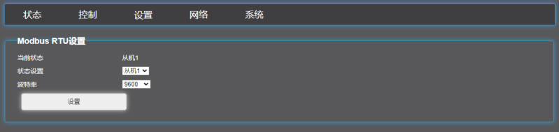 Note: The function codes and storage addresses of IPDU and DPDU are the same
IPDU cannot control the switch, so all relay information cannot be read
Example illustration
Read switch status (1-8)Sent: 02 03 00 30 00 01 84 36Total voltage readingSend 02 04 00 03 00 01 C1 F9Low level reading of total currentSend 02 04 00 05 00 01 21 F8Active power factorReturn to 02 04 00 05 11 3E 6C analysis 05 11power factorReturn 02 04 02 03 E8 FD 8E Analysis 03 E8power levelReturn 02 04 02 08 FD 96 Analysis 02 08Branch Data Storage address 200-205, first socket dataFirst voltage reading:S: 02 04 00 C8 00 01 B0 07First current reading:S: 02 04 00 C9 00 01 E1 C7First power reading:S:02 04 00 CA 00 01 11 C7First power factor reading:S:02 04 00 CB 00 01 40 07First high level reading of electrical energy:S:02 04 00 CC 00 01 F1 C6
Note: The function codes and storage addresses of IPDU and DPDU are the same
IPDU cannot control the switch, so all relay information cannot be read
Example illustration
Read switch status (1-8)Sent: 02 03 00 30 00 01 84 36Total voltage readingSend 02 04 00 03 00 01 C1 F9Low level reading of total currentSend 02 04 00 05 00 01 21 F8Active power factorReturn to 02 04 00 05 11 3E 6C analysis 05 11power factorReturn 02 04 02 03 E8 FD 8E Analysis 03 E8power levelReturn 02 04 02 08 FD 96 Analysis 02 08Branch Data Storage address 200-205, first socket dataFirst voltage reading:S: 02 04 00 C8 00 01 B0 07First current reading:S: 02 04 00 C9 00 01 E1 C7First power reading:S:02 04 00 CA 00 01 11 C7First power factor reading:S:02 04 00 CB 00 01 40 07First high level reading of electrical energy:S:02 04 00 CC 00 01 F1 C6
Separate switch command
The first socketClose: 02 06 00 34 01 01 08 67Second socketClose: 02 06 00 34 02 01 08 97Third socketClosed: 02 06 00 34 03 01 09 07The fourth socketClose: 02 06 00 34 04 01 0B 37The fifth socketClose: 02 06 00 34 05 01 0A A7The sixth socketClosed: 02 06 00 34 06 01 0A 57The seventh socketClose: 02 06 00 34 07 01 0B C7The eighth socketClose: 02 06 00 34 08 01 0E 37
Modbus TCP Sending Method
Example of First Channel Switch