
Description
Product Introduction1.1 Product Overview
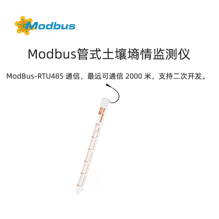
Soil Moisture Monitoring Instrument is a sensor based on the principle of dielectric constant. This detector can dynamically observe the soil moisture content and temperature status at different levels. It can detect the temperature and humidity status of at least 3 layers of soil and up to 5 layers of soil. It is equipped with a tilt angle device to monitor the tilt angle of the soil to determine the soil and equipment status. There is also an advanced version of the tubular soil moisture monitoring device, which is made of sealed material and can be completely waterproof.
1.2 Product Features
The product shell is made of PVC plastic pipe, which emits high-frequency detection waves of nearly 1GHz inside, which can penetrate the plastic pipe and effectively sense the soil environment.
1.3 Technical Parameters
| Operating Temperature | -40℃-80℃ | ||
| measurement range | soil moisture | 0~100% | |
| soil temperature | -15 ℃~35 ℃ | ||
| Tilt angle | -90 °~90 ° | ||
| measurement accuracy | soil moisture | ±5% (@50%,25℃) | |
| soil temperature | ±0.5℃ (25℃) | ||
| Tilt angle (typical precision) | X. Y-axis | Static accuracy ± 0.1 °, dynamic accuracy ± 0.5 ° | |
| Z-axis | Static accuracy ± 0.5 °, dynamic integration error exists | ||
| Temperature drift (inclination angle) | ± (0.5 °~ 1 ° ) , (-40°C ~ +60°C ) | ||
| Distance between measurement points | 10cm | |
| power supply method | 10-30V wide DC power supply | |
| Materials used for the shell | PVC plastic pipe | |
| Protection Rating | Below ground level IP68 | |
| output signal | RS485 (ModBus protocol) | |
| power consumption | three floors | 0.7W |
| five floors | 0.96W | |
| response time | ≤60s | |
The performance data stated above was obtained under testing conditions using our company's testing system and software. In order to continuously improve our products, our company reserves the right to change design features and specifications without prior notice.1.4 Product Selection
| RS- | Company Code | |||
| 3S | Detect the moisture content of three layers of soil | |||
| 4S | Detect the moisture content of four layers of soil | |||
| 5S | Detect the moisture content of 5 layers of soil | |||
| 3W3S | Detect the temperature and humidity of three layers of soil | |||
| 4W4S | Detect the temperature and humidity of four layers of soil | |||
| 5W5S | Detect the temperature and humidity of 5 layers of soil | |||
| Q3S | Detection of moisture and dip angle in 3 layers of soil | |||
| Q4S | Detection of moisture and dip angle in 4 layers of soil | |||
| Q5S | Detection of moisture and dip angle in 5 layers of soil | |||
| Q3W3S | Detection of temperature, humidity and dip angle in 3 layers of soil | |||
| Q4W4S | Detection of temperature, humidity and dip angle in 4 layers of soil | |||
| Q5W5S | Detection of temperature, humidity and dip angle in 5 layers of soil | |||
| N01- | Standard ModBus-RTU485 Communication | |||
| TR-6 | Advanced version tubular soil moisture monitoring instrument | |||
Equipment installation instructions
2.1 Equipment size and detection height
The product adopts a layered observation structure, with one temperature observation point on the ground and one temperature observation point every 10cm for the underground soil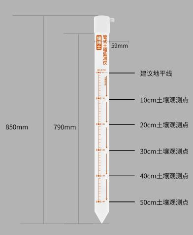
2.2 Pre installation inspection of equipment
Equipment List:
2.2.1 Installation location selection
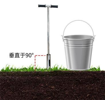
Install equipment after sowing crops;Attention: The installation location of the equipment should be chosen at a relatively high altitude to prevent rainwater from pouring into the interior of the equipment and causing short circuits or circuit failures. 2.3 Installation MethodStep 1: Use a soil drill to drill holes in the appropriate position1. Place the soil drill vertically on the ground, hold the handle tightly with both hands, press down clockwise, and rotate slowly. (Attention: Do not apply too much force, make sure to rotate slowly for a few more turns to prevent the drill bit from deviating and causing the hole to become crooked.)
- Remove the soil drill from the hole, place it in a bucket, and collect the soil from the drill into the bucket using the following steps and mud. (Note: Due to excessive impurities in the first drilling soil, it will not be collected.)
- Repeat the drilling and soil sampling process repeatedly, and try to gently insert the sensor into the hole during this process (do not forcefully touch the bottom of the device) to test whether the depth of the hole is appropriate; If there is any lag, use a soil drill to correct it to ensure smooth insertion and removal of the sensor; Until the hole depth is flush with the installation position marked by the sensor, the drilling is completed.
 Step 2: Make Mud
1. Remove impurities such as stones, grass roots, and insoluble soil blocks from the soil drilled out. Grind the soil fine to mix with the mud.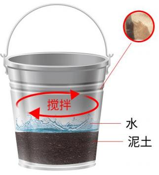 Step 3: Grouting installation
- Slowly pour the mud into the hole, about 1/2 of the hole position; It can be adjusted according to the actual situation.
- Slowly insert the sensor into the hole, rotate it in one direction and press it down. If the speed is too fast, it may cause the bubbles to not be completely expelled. (Note: During the process of rotating and pressing down again, do not pull up the sensor to prevent gas from being sucked into the hole again)
3. After the sensor is installed at the correct depth, some mud will overflow around the equipment, and grouting is completed; At this point, the installation depth of the sensor is flush with the hole opening. (Note: Remove excess mud 3cm away from the sensor to prevent clumping and moisture infiltration)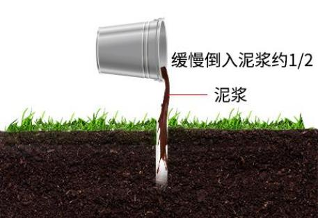 Step 4: Installation completedAfter connecting the device to the power cord and 485 communication line, the device will make a beep sound and start working normally. It is recommended to resume normal work after the mud has returned to its normal state.Key points for sand installationThe installation steps for sandy soil are no different from those for loam soil. It is important to prepare sufficient water, not less than 5L. Before grouting, pour water into the hole and wet the entire wall until excess water appears at the bottom of the hole. Then, following the steps, slowly pour the mud into the hole, approximately at 1/2 position of the hole. The remaining installation steps can refer to the installation of loam soil.Key points for clay installationThe installation of clay is carried out after drilling and collecting soil, cleaning impurities, and soaking the clay in water for more than 4 hours to soften it and facilitate the formation of a relatively uniform slurry. After soaking, stir until viscous, and then grout. The remaining installation steps can refer to the installation of loam soil.
2.4 Product wiring instructions
Power supply and 485 signalWide voltage power supply can input 10-30V. When wiring the 485 signal line, be careful not to connect wires A and B in reverse, and ensure that the addresses of multiple devices on the bus do not conflict.
| line color | Explanation | |
| Power supply | brown | Positive power supply (10~30V DC) |
| Black | Negative power supply | |
| Communication | Yellow (green) color | 485-A |
| blue | 485-B |
Install and use configuration software
3.1 Software Selection
Open the package, select "Debugging Software" ->"485 Parameter Configuration Software", find "Yes" and open it. Note: When using this configuration software to change the address and baud rate, only one device can be connected.3.2Parameter Settings
communication protocol
4.1 Basic communication parameters
| Encoding | 8-bit binary |
| data bit | 8 digits |
| parity bit | None |
| stop bit | 1 person |
| Error Check | CRC (Redundant Cyclic Code) |
| Baud Rate | 2400bit/s, 4800bit/s, 9600 bit/s can be set, factory default is 4800bit/s |
4.2Data Frame Format Definition
Adopting ModBus RTU communication protocol, the format is as follows:Host query frame structure:
| address code | function code | Register starting address | Register Length | checksum low bit | checksum high bit | ||||
| 1 byte | 1 byte | 2 bytes | 2 bytes | 1 byte | 1 byte |
| Address code | Function code | Effective byte count | Data Area 1 | Second Data Area | Nth Data Area | checksum |
| 1 byte | 1 byte | 1 byte | 2 bytes | 2 bytes | 2 bytes | 2 bytes |
4.3 Register Address
| Register | PLC or configuration | Content | function code |
| 0000 H | 40001 | The first layer of soil moisture (10 times the actual value) | 03/04 |
| 0001 H | 40002 | The temperature of the first layer of soil (10 times the actual value) | 03/04 |
| 0002 H | 40003 | Second layer soil moisture (10 times actual value) | 03/04 |
| 0003 H | 40004 | Second layer soil temperature (10 times actual value) | 03/04 |
| 0004 H | 40005 | Third layer soil moisture (10 times actual value) | 03/04 |
| 0005 H | 40006 | Third layer soil temperature (10 times actual value) | 03/04 |
| 0006 H | 40007 | Fourth layer soil moisture (10 times actual value) | 03/04 |
| 0007 H | 40008 | Fourth layer soil temperature (10 times actual value) | 03/04 |
| 0008 H | 40009 | Fifth layer soil moisture (10 times actual value) | 03/04 |
| 0009 H | 40010 | Fifth layer soil temperature (10 times actual value) | 03/04 |
| 003C H | 40061 | Angle (100 times the actual value) | 03/04 |
| 003D H | 40062 | X-axis angle component (floating point type) | 03/04 |
| 003E H | 40063 | ||
| 003F H | 40064 | Y-axis angle component (floating point type) | 03/04 |
| 0040 H | 40065 | ||
| 0041 H | 40066 | Z-axis angle component (floating point type) | 03/04 |
| 0042 H | 40067 | ||
| 0043 H | 40068 | X-axis acceleration component (floating point type) | 03/04 |
| 0044 H | 40069 |
| 0045 H | 40070 | Y-axis acceleration component (floating point type) | 03/04 |
| 0046 H | 40071 | ||
| 0047 H | 40072 | Z-axis acceleration component (floating point type) | 03/04 |
| 0048 H | 40073 | ||
| 07D0 H | 42001 | Address | 03/06 |
| 07D1 H | 42002 | Baud rate (0 represents 2400 1 represents 4800) | 03/06 |
4.4 Example and Explanation of Communication Protocol
Example: Read device address0x01 The first layer of soil temperature and moisture valuesInquiry frame (hexadecimal):
| address code | function code | starting address | data length | Low bit of verification code | High bit of verification code | |
| 0x01 | 0x03 | 0x00 0x00 | 0x00 0x02 | 0xC4 | 0x0B |
(For example, reading a temperature of -10.1 ℃ and a moisture content of 65.8% RH)
| address code | function code | Return the number of valid bytes | Moisture value | temperature value | Low bit of verification code | High bit of verification code | |||
| 0x01 | 0x03 | 0x04 | 0x02 0x92 | 0xFF 0x9B | 0x5A | 0x3D |
When the temperature is below 0 ℃, the temperature data is uploaded in the form of a supplementary code.Example:Read device address0x01 The angle valueInquiry frame (hexadecimal):
| Address code | Function code | Starting address | Data length | Check code low | Check code high | |
| 0x01 | 0x03 | 0x00 0x3C | 0x00 0x01 | 0x44 | 0x06 |
(e.g. reading an angle value of 80 °)
| Address code | Function code | Return of valid bytes | Angle value | Check code low bit | Check code high bit | ||
| 0x01 | 0x03 | 0x02 | 0x1F 0x40 | 0xB1 | 0x84 |
Example: Read device address0x01 TheX Axis angle component valueInquiry frame (hexadecimal):
| address code | function code | starting address | data length | Check code low bit | Check code high bit |
| 0x01 | 0x03 | 0x00 0x3D | 0x00 0x02 | 0x55 | 0xC7 |
(For example, reading that the X-axis angle component value is 90 °)
| address code | function code | Return the number of valid bytes | high position | low position | Low bit of verification code | High bit of verification code | |||
| 0x01 | 0x03 | 0x04 | 0x42 0xB4 | 0x00 0x00 | 0xAE | 0x6D |
Example: Read device address0x01 TheX Axial acceleration component valueInquiry frame (hexadecimal):
| address code | function code | starting address | data length | Low bit of verification code | High bit of verification code | |
| 0x01 | 0x03 | 0x00 0x43 | 0x00 0x02 | 0x35 | 0xDF |
(For example, reading that the X-axis acceleration component value is 0.5g)
| address code | function code | Return the number of valid bytes | high position | low position | Low bit of verification code | High bit of verification code | |||
| 0x01 | 0x03 | 0x04 | 0x3F 0x00 | 0x00 0x00 | 0xF6 | 0x27 |