
Description
Product Introduction1.1 Product Overview
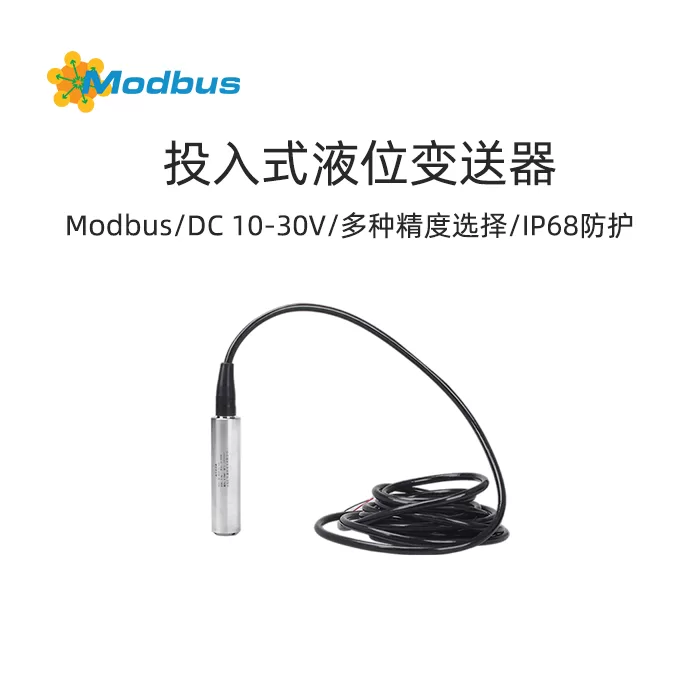
The front protective cap of the Modbus input type liquid level transmitter serves to protect the sensor diaphragm and ensure smooth liquid contact with the diaphragm. The waterproof wire is sealed and connected to the housing, and the ventilation pipe is connected to the outside inside of the cable. The internal structure is designed to prevent condensation. Built in micro signal processing circuit, capable of remote transmission. Has good stability and reliability. This product is developed using imported diffusion silicon chips and low-power ADI professional chips combined with microprocessor technology. The Modbus input liquid level transmitter has RS485 communication function, small size, high accuracy, light weight, and wide range coverage. It is suitable for various industries that require precise measurement of fluid pressure and is widely used in industrial process control, petroleum, agriculture, irrigation, IoT and other industries.
1.2 Features
1. Reverse polarity protection and instantaneous overcurrent and overvoltage protection comply with EMI protection requirements;
1.3 Main technical parameters
| DC power supply (default) | DC 10-30V, typical 24V |
| Maximum Power Consumption | 0.2W |
| Working temperature and humidity of transmitter circuit | -20~80℃ |
| Overload capacity | <1.5 times range |
| Protection level | IP68 |
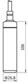
| Outer diameter size | Ø 26.8mm |
| Measurement medium | Non corrosive to stainless steel oil, water, etc. (long-term measurement requires ≤ 60 ℃) |
| Sampling time | 2400 times/s |
| Long term stability | ± 0.2% FS/year |
1.4 Product Selection
| RK- | Company Code | ||||
| PM200- | Universal input type liquid level transmitter | ||||
| 01~99- | Range (99 represents customized range, other values are range meters) | ||||
| N01- | 485 communication (ModBus RTU protocol) | ||||
| A05 | 0.5 level accuracy (default), optional 0.2 level accuracy (A02) | ||||
Product Dimensions
Equipment installation instructions
3.1 Pre installation inspection of equipment
Equipment List:3.2 Wiring InstructionsOrBrown wire: 24VDC power supply+Special note:1) There are certain standard requirements for on-site wiring of 485 equipment. For details, please refer to the data package "485 Equipment On site Wiring Manual".
Equipment configuration before use
4.1 Software Selection
Open the package, select "Debugging Software" - "485 Parameter Configuration Software", find the circle, and open it.
4.2 Parameter Settings
① Select the correct COM port (check the COM port in "My Computer - Properties - Device Manager - Ports"), and the following figure lists the driver names of several different 485 converters.
communication protocol
5.1 Basic communication parameters
| Encoding | 8-bit binary |
| data bit | 8 digits |
| parity bit | None |
| stop bit | 1 person |
| Error Check | CRC (Redundant Cyclic Code) |
| Baud Rate | 1200~115200 can be set, default 4800 |
5.2Data Frame Format Definition
adopts ModBus RTU communication protocol, with the following format:
| address code | function code | Register starting address | Register Length | Low bit of verification code | Check code high bit | ||
| 1 byte | 1 byte | 2 bytes | 2 bytes | 1 byte | 1 byte |
Slave response frame structure:
| Address code | Function code | Effective bytes | Data area 1 | Second data area | Nth data area | Check code |
| 1 byte | 1 byte | 1 byte | 2 bytes | 2 bytes | 2 bytes | 2 bytes |
5.3 Register address
| Register Address | PLC or Configuration Address | Content | Support Function Code |
| 0002 H | forty thousand and three | Unit Type | 0x03/0x04 |
| 0003H | 40004 | Number of decimal points | 0x03/0x04 |
| 0004H | 40005 | Measurement Output Value | 0x03/0x04 |
| 0005H | 40006 | Transmitter Range Zero Point | 0x03/0x04/0x06 |
| 0006H | 40007 | Transmitter Range Full Point | 0x03/0x04/0x06 |
| 000CH | 40013 | Offset Value | 0x03/0x04/0x06 |
5.4Communication Protocol Example and Explanation
Read Device Address0x01 Real time ValueInquiry Frame (hexadecimal):
| Address Code | Function Code | Starting Address | Data Length | Check Code Low Bit | Check Code High Bit | |||
| 0x01 | 0x03 | 0x00 0x04 | 0x00 0x01 | 0xC5 | 0xCB |
Response frame (hexadecimal): (For example, for a level gauge with a range of 0-3 meters, the decimal place is 3 and the read value is 101)
| address code | function code | Return valid words | real-time value | Low verification code | High bit of verification code | ||
| 0x01 | 0x03 | 0x02 | 0x00 0x65 | 0x78 | 0x6F |
Actual real-time value calculation:
Precautions
Our company's products come with user manuals and certificates of conformity, which include technical parameters. Please carefully check to avoid using them incorrectly.
Common problems and solutions
The device cannot connect to the PLC or computer