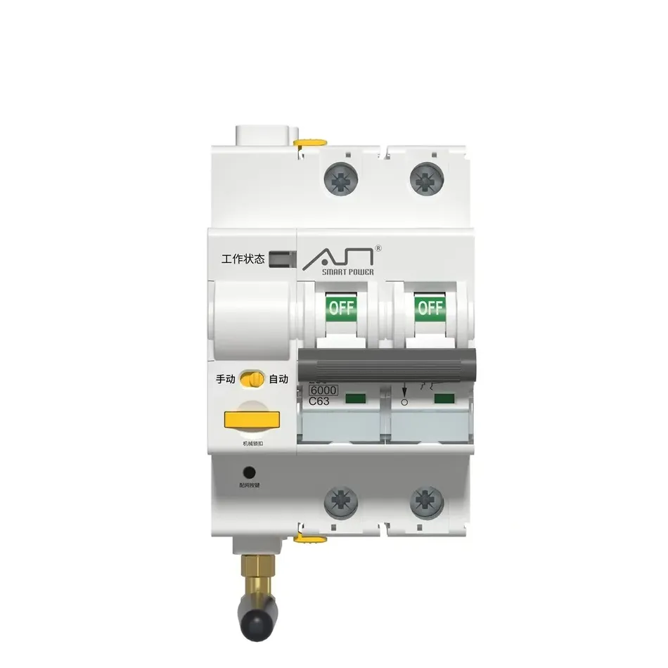
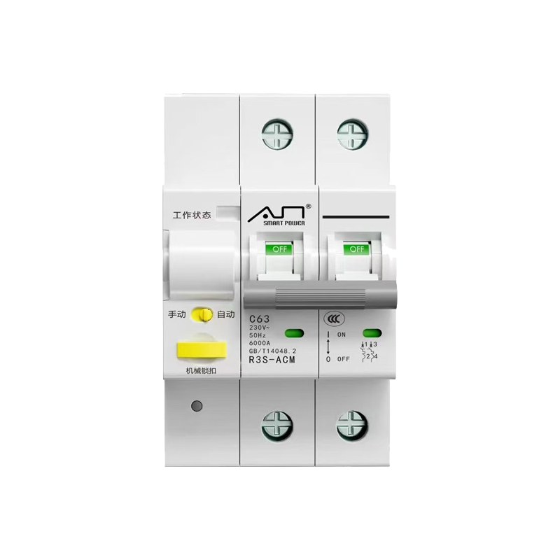
Intelligent Circuit Breaker Product Manual

freeFree Technical Resource

This content is free to read, suitable for basic learning and search traffic.

Intelligent Circuit Breaker Product Manual
Intelligent Circuit Breaker Product ManualFigure

1. Product Overview

A smart circuit breaker integrated with Modbus communication protocol, suitable for distribution systems with AC 50/60Hz, rated voltage 230/400V, current 63A and below. Supporting remote control, overvoltage and undervoltage protection, automatic reclosing, and other functions, it can be widely used in smart grids, industrial automation, and building power distribution scenarios.

Product purchase:https://www.modbus.cn/product/30887.html

2. Functional Features

  • Core Functions
    • Over and Under Voltage Protection: The threshold can be configured, supporting automatic opening and closing and recovery mechanisms.
    • Leakage protection (optional): 30mA/100mA/300mA graded tripping, response time<100ms.
    • Multi mode control: local manual, remote command, dry wet contact (optional), timed operation (optional).
    • Automatic Recloser: 5-level cycle interval (adjustable from 60s to 3600s), stable time configuration.
  • Communication Capability
    • Modbus RTU Protocol: Supports read/write operations, address range 1-247, broadcast address 0 (read only).
    • Multi protocol compatibility: RS485 (default), WiFi (graffiti platform) ZigBee.
  • Status indicator
    • indicator light:
      • Green light (closed), red light (open/faulty), orange light (manual mode).
      • The flashing frequency distinguishes the type of fault (such as 100ms flash for mechanism fault, 500ms for overvoltage disconnection).
    • Fault TypeOvervoltage, undervoltage, overcurrent, leakage, hardware failure (EEPROM/clock chip, etc.).

3. Technical Parameters

ProjectParameter Values
Electrical Parameters
Rated VoltageAC230V/400V
Rated Current16A/25A/32A/60A/63A
Breaking Capacity6000A (Ics)
Minimum Operating Voltage≥70VAC
Communication parameters
Communication InterfaceRS485 (twisted pair shielded wire)
Baud rate2400/4800/9600 (default 9600)
verification methodOdd check/even check/no check
mechanical parameters
Installation method35.5 × 7.5mm standard guide rail
mechanical life10000 times
Wiring cross-sectional area≤25mm²

4. Installation and wiring

  • Installation requirements
    • Vertically installed in a dry and ventilated environment, avoiding high temperatures (>40 ℃) and condensation.
    • Use M5 screws to fix the guide rail and ensure that the mechanical lock is secure.
  • Wiring Specification
    • Power Line: Neutral and live wires must not be reversed, and the cable cross-sectional area should be ≤ 25mm ².
    • Communication line: Twisted shielded wire (2 × 0.5mm ²), single ended grounding of shielding layer, bus length ≤ 1200m.

5. Full Analysis of Modbus Communication Protocol

5.3 Register Definition (Complete Classification)

5.3.2 Status Monitoring Register
1. Opening and Closing Status Encoding Table (Address 0x5000)
Status CodeMeaningExplanation
0Manual OpeningLocal Manual Operation Opening
1Instruction OpeningRemote Instruction Triggered Opening
2Fault Opening (Overvoltage)Voltage exceeding overvoltage threshold triggers opening
3Fault opening (undervoltage)Voltage below undervoltage threshold triggers opening
4Manual closingLocal manual operation closing
5Command closingRemote command triggering closing
6Automatic closingAutomatic reclosing function triggers closing
7Command lockingRemote locking state, which needs to be unlocked before closing
8Fault (initialization/equipment failure)Device initialization failure or hardware failure
9Mechanism padlockMechanical padlock lock, prohibit closing
10Timed openingTimed function triggers opening
11Timed closingTimed function triggers closing
14Dry contact openingDry contact signal triggers opening
15Dry contact closingDry contact signal triggers closing
16Manual mode openingManual mode opening
17Manual mode closingManual mode closing
2. Fault status bit mapping table (address 0x5003)
BitAlarm typeDescription (Bit=1 indicates alarm triggering)
0A-phase overvoltage alarmA-phase voltage exceeding overvoltage threshold
1B-phase overvoltage alarmB-phase voltage exceeding overvoltage threshold
2C-phase overvoltage alarmC-phase voltage exceeds overvoltage threshold
3A-phase undervoltage alarmA-phase voltage below undervoltage threshold
4B-phase undervoltage alarmB-phase voltage below undervoltage threshold
5C-phase undervoltage alarmC-phase voltage below undervoltage threshold
6A-phase overcurrent alarmA-phase current exceeds rated value
7B-phase overcurrent alarmB-phase current exceeds rated value
8C-phase overcurrent alarmC-phase current exceeds rated value
9A-phase over power alarmA-phase power exceeds set threshold
10B-phase over power alarmB-phase power exceeds set threshold
11C-phase over power alarmC-phase power exceeds set threshold
12Voltage imbalance alarmThree phase voltage difference exceeds allowable range
13Leakage protection triggersLeakage current exceeds set value (RCD version only)
14Motor reset failureMotor reset abnormal during automatic closing
15Communication module faultRS485/WiFi/ZigBee communication abnormal
5.3.3 Other key register supplements
1. Recloser event record (address 0x5300~0x5303)
Address (Hex)Data itemRead/write attributeValue range/description
5300Fault time (year/month)RHigh byte: year (00~99), Low byte: month (01~12)
5301Fault time (day/hour)RHigh byte: day (01~31), low byte: hour (00~23)
5302Fault time (minutes and seconds)RHigh byte: minutes (00~59), low byte: seconds (00~59)
5303Fault causeR0=overvoltage, 1=undervoltage, 2=overcurrent, 3=overpower
2. Timing control configuration (addresses 0x6D00~0x6D0E)
Address (Hex)Data itemRead and write attributesNumerical range/description
6 D00timer switchR/W0=Off, 1=Enable
6D01~6D08Timing Operation Time 1~8R/WHigh Byte: Hour (0~23), Low Byte: Minute (0~59)
6D09~6D0ETiming Operation 1~6R/W0=No Operation, 1=Open, 2=Close
3. Special Function Register (Address 0xF205~0xF380)
Address (Hex)Data ItemRead/Write AttributeWrite Value/Description
F205Factory ResetWWrite 0x0042 (Trigger Recovery)
F206Device RestartWWrite 0x0043 (Trigger Restart)
F300Remote Upgrade CommandW0x3901=Start Upgrade, 0x3903=End Upgrade
F303~F380Upgrade Package DataWWrite Upgrade Data in Package Number Order

6. Operation example and data parsing (including complete CRC)

Example 1: Read on/off status (address 0x5000)

  • Request frame(device address 1):
  01 03 50 00 00 01 85 C8  
  • CRC calculation: 0x85C8(calculated through CRC-16/A001).
  • Response frame(status code=3, fault disconnection):
  01 03 02 00 03 35 29  
  • Data parsing: 00 03→ Status code 3 (fault disconnection).

Example 2: Set overvoltage threshold to 300.0V (address 0x6601)

  • Request frame(Device Address 1):
  01 06 66 01 0B B8 1A 7F  
  • Data Analysis: 0B B8=3000 → 300.0V, CRC=0x1A7F.

7. Precautions and Safety Warning

  • Register Write Restriction:
  • Read only registers (such as electrical parameters, fault status) are prohibited from being written, otherwise an exception code 0x03 will be triggered.
  • The string register (such as latitude and longitude) needs to be split according to the low byte ofbefore(Example:"123.56" → 31 32 33 2E 35 36) .
  • Timer function configuration:
  • The scheduled operation time should be set according to actual needs to avoid conflicts.
Related Tags
Put this resource to use in a real project?

Go to the Tool Center for message parsing, CRC verification and device debugging, or submit your requirements for selection and integration advice.

Engineer Membership

Turn this article into actionable debugging resources

After activation, you can use advanced message parsing, resource pack downloads, code examples, engineering cases and priority technical support, suitable for real project delivery.

Unlimited Advanced Tools
Resource & Code Packs
Complete Engineering Case Library
Priority Technical Support

Leave a Reply

Your email address will not be published. Required fields are marked *.