
What is a communication protocol?
Before understanding what Modbus is, let's first take a look at what communication protocol is.
- Data format:The communication protocol specifies the format of data, including the encoding method, byte order, and structure of data frames. This ensures that the data can be correctly parsed and reconstructed during transmission.
- Communication method:The protocol defines communication methods, including simplex communication (one-way transmission), half duplex communication (alternating transmission between both parties), and full duplex communication (simultaneous two-way transmission).
- Error detection and correction:Communication protocols typically include mechanisms for detecting and correcting errors that may occur during transmission to ensure data integrity and accuracy.
- Flow control:Communication protocols can define how to control the flow of data to avoid data overload or congestion, thereby improving communication efficiency.
- Address and identification:The protocol can include the address and identification of the device or node to ensure that data is correctly sent to the target device.
- Session management:In some protocols, session management is used to establish, maintain, and terminate communication sessions, ensuring the orderliness and controllability of communication.
Our common communication protocols include I2C, SPI, UART, etc., while Modbus is a serial communication protocol.
What are RS-485 and RS-232?
When discussing Modbus, RS-485 and RS-232 are often encountered, so what exactly are they?RS-232:
- Single port communication:RS-232 is a single port communication standard, where data signals are transmitted through only one transmission line, which includes a transmit line (TX) and a receive line (RX).
- Voltage level:RS-232 uses voltage levels to represent data bits. A typical RS-232 voltage level is positive and negative 12V, where positive voltage represents logic 0 and negative voltage represents logic 1.
- Communication distance:RS-232 communication is typically suitable for shorter distances, with communication distances typically not exceeding 50 feet (about 15 meters), and communication speed is limited by distance.
- Point to point communication:RS-232 communication is point-to-point, and each connection only supports communication between two devices, one sender and one receiver.
- Purpose:RS-232 is commonly used to connect computers and external devices such as serial printers, modems, serial mice, etc. It can also be used for short-range point-to-point communication.
- Differential signal:RS-485 uses differential signaling to transmit data, which includes two transmission lines, one positive (A or non inverting) and one negative (B or inverting). This differential signal can improve anti-interference performance.
- Voltage level:RS-485 typically uses low-level differential signals, where the voltage on the positive line is roughly equal to the voltage on the negative line, which helps reduce interference on the transmission line.
- Communication distance:RS-485 communication is suitable for longer distances, typically covering distances of several thousand feet (hundreds of meters), depending on communication speed and cable quality.
- Multi point communication:RS-485 supports multi-point communication, allowing multiple devices to be connected to the same transmission line and communicate simultaneously. This makes RS-485 very suitable for applications such as industrial control and instrumentation, where data exchange between multiple devices is required.
- Purpose:RS-485 is commonly used in industrial automation, remote monitoring, building automation, and other applications that require long-distance and multi device communication. It is widely used in these fields because its differential signal design makes it more resistant to interference, adaptable to longer communication distances, and supports multi-point communication.
 If you would like to further understand, please continue reading:
USB to Serial TTL RS-232 RS-485 COM UART Differences
USB to Serial is a device that connects a USB interface to a serial communication interface, typically used to connect a computer to external devices that require serial communication. These serial ports can be TTL serial ports, RS-232 serial ports, or RS-485 serial ports, with the following specific differences:
- TTL serial port:TTL (Transistor Transformer Logic) serial ports communicate using a low level (usually 0V for logic 0, 3.3V or 5V for logic 1). It is commonly used for communication between embedded systems and microcontrollers. USB to TTL serial port is suitable for connecting computers and TTL serial devices, such as Arduino.
- RS-232 serial port:RS-232 is a common serial communication standard that typically uses positive and negative 12V voltage levels to represent logic 0 and logic 1. USB to RS-232 serial port is suitable for connecting computers with old-fashioned serial devices such as serial printers, modems, etc.
- RS-485 serial port:RS-485 is a differential signal serial port standard that uses two transmission lines (A and B) to transmit data, one of which is in phase and the other is in phase. It has anti-interference and the ability to support multi-point communication, and is usually used for industrial control and long-distance communication. USB to RS-485 serial port is suitable for connecting computers and RS-485 serial port devices, such as industrial automation equipment.
- COM port (serial port):COM port is a physical interface used for serial communication on computers, typically using RS-232 or RS-485 standards. COM ports are typically used to connect external devices such as serial printers, GPS receivers, data collectors, etc. USB to COM port is suitable for situations where computers do not have built-in serial interfaces, allowing users to simulate COM ports through USB interfaces.
- UART (Universal Asynchronous Receiver Transmitter):UART is a communication chip or module used to convert parallel data into serial data for serial communication. UART can be used in conjunction with different types of serial ports such as TTL, RS-232, or RS-485. USB to UART is usually a universal serial port adapter that can be used to connect different types of serial devices.
Modbus Protocol Description
Modbus was born in 1979, initially developed by Modicon and later acquired by Schneider Electric. Modbus provides a universal language for communication between devices. It has become the industry standard for communication protocols in the industrial field and is one of the commonly used connection methods between industrial electronic devices. Modbus, as one of the most widely used protocols in the industrial field, has the following advantages:
Application of Modbus Protocol
Simply put, Modbus is a bus communication protocol similar to I2C and SPI, but not dependent on a specific hardware bus. Modbus is widely used because it has many advantages.
Modbus communication process
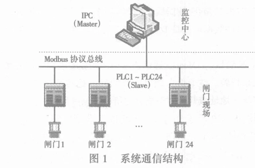
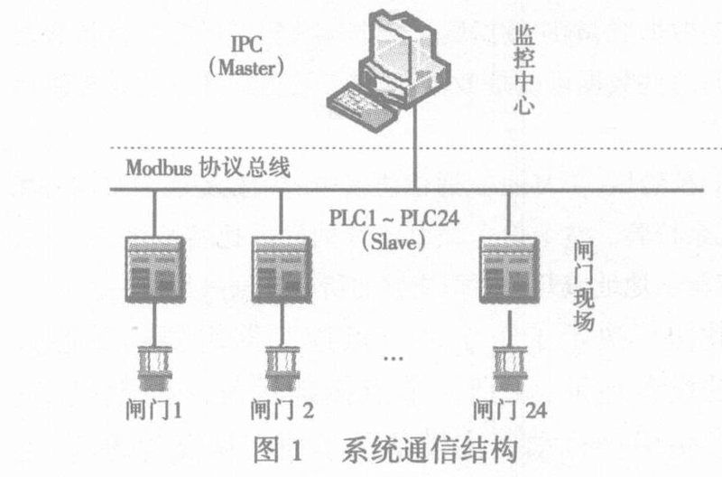
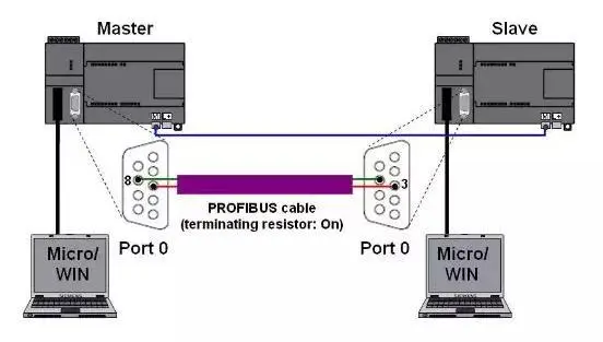
It should be noted that Modbus is a one master multiple slave communication protocol. In Modbus communication, only one device can send requests, while other slave devices receive request data sent by the host and respond. The slave device can be various peripheral devices, such as I/O sensors, valves, network drivers, or other types
Modbus storage area
Since data is stored on the slave, there must be a way to perform file operations. We all know that files can be divided into two types: Read Only (- R) and Read Write (- RW), and Modbus also has corresponding storage areas.
Modbus protocol type
In the Modbus protocol, data transmission can use different media and modes, with three main message types including ASCII, RTU (Remote Terminal Control System), and TCP.
Modbus RTU protocol
Modbus message frame structureModbus message refers to a frame of data sent from a master to a slave, which includes the address of the slave, the operations to be performed by the master, data, and checksum information. On the serial link, the format of Modbus messages is as follows:
Modbus Function Code
The Modbus protocol specifies multiple function codes, each corresponding to a specific operation. Although Modbus defines over 20 functional codes, only 8 of them are commonly used in practical applications for reading and writing to storage areas. The following are commonly used Modbus function codes:
CRC check
CRC (Cyclic Redundancy Check) is used to detect errors during data transmission. In the Modbus protocol, the CRC check occupies two bytes and contains a 16 bit binary value. The CRC value is calculated by the sending device and attached to the data frame. When the receiving device receives data, the CRC value is recalculated and compared with the received CRC check value. If these two values are not equal, it indicates that there is an error in data transmission.
Example of sending and receiving data
Below, we will provide a detailed introduction to the sending and receiving data examples of the Modbus RTU protocol.1. Host to slave data reading operationThe format of the message sent by the host is as follows:2. Host to slave write data operationThe format of the message sent by the host is as follows:Explanation:The reply from the slave is the same as the sending from the host. If they are different, it means an error has occurred.
Modbus ASCII protocol
The Modbus ASCII protocol is similar to the Modbus RTU protocol, but each byte in the message is sent as two ASCII characters. Hexadecimal 0 to F correspond to ASCII characters 0 to 9 and A to F, respectively.
Modbus TCP protocol
The Modbus TCP protocol is a variant of the Modbus protocol based on the TCP/IP protocol, used for communication over TCP/IP networks. Unlike the Modbus RTU and Modbus ASCII protocols, the Modbus TCP protocol does not use physical serial links, but instead utilizes TCP/IP networks such as Ethernet or Wi Fi.
Summary
Modbus is a universal protocol used for industrial communication, with multiple versions including Modbus RTU, Modbus ASCII, and Modbus TCP. Different versions are suitable for different communication media and scenarios. Modbus RTU is typically used for serial communication, while Modbus TCP is used for Ethernet communication. The Modbus protocol includes elements such as function codes and CRC checks, used for sending and receiving data. Using the Modbus protocol, the master can communicate with the slave, read and write data to achieve automation and control systems.


Leave a Reply